

Pepperl Fuchs SLCT, SLCT 35 ORIGINAL INSTRUCTIONS
AOPD
3AA2
UL File Number: E215245
EN
ORIGINAL INSTRUCTIONS
SLCT* and SLCT*/35
safety light curtains
FACTORY AUTOMATION

EN
SLCT* and SLCT*/35 safety light curtains
With regard to the supply of products, the current issue of the following document
is applicable: The General Terms of Delivery for Products and Services of the Electrical Industry, published by the Central Association of the Electrical Industry (Zen-
tralverband Elektrotechnik und Elektroindustrie (ZVEI) e.V.) in its most recent
version as well as the supplementary clause: "Expanded reservation of proprietor-
ship"

SLCT* and SLCT*/35 safety light curtains
EN
Contents
1 Introduction......................................................................... 3
1.1 Content of this Document .............................................................................3
1.2 Symbols Used...............................................................................................3
2 Safety information.............................................................. 5
3 Product Description ........................................................... 7
3.1 Use and Application......................................................................................7
3.2 Indicators and Operating Controls ................................................................9
3.3 Interfaces and Connections........................................................................10
3.4 Scope of Delivery........................................................................................11
4 Installation ........................................................................ 12
4.1 Planning and Preparation............................................................................12
4.2 Mounting.....................................................................................................16
4.3 Reflection....................................................................................................19
4.4 Connection and Operating Mode Setting....................................................20
4.4.1 Signal outputs on the receiver unit..........................................................21
4.4.2 Signal Inputs on the Transmitter Unit ......................................................22
4.4.3 Signal inputs on the receiver unit............................................................23
4.4.4 Typical circuits ........................................................................................25
5 Commissioning................................................................. 26
5.1 Functional Testing .......................................................................................26
5.2 Multiple Positions........................................................................................27
6 Maintenance and Repair.................................................. 29
6.1 Maintenance...............................................................................................29
6.2 Periodic Checks..........................................................................................29
6.3 Repairs .......................................................................................................30
7 Troubleshooting................................................................ 31
7.1 Troubleshooting ..........................................................................................31
8 Appendix ........................................................................... 33
8.1 Technical Data ............................................................................................33
8.1.1 Functional Safety Standards and Parameters.........................................36
8.2 Safety Light Curtains - Profile Lengths and Weight .....................................37
8.3 Dimensional Drawing ..................................................................................39
8.4 Type Code...................................................................................................39
8.5 Application Checklist ..................................................................................44
271695 2020-02
1

SLCT* and SLCT*/35 safety light curtains
EN
Contents
8.6 Accessories ............................................................................................... 46
8.6.1 Mounting Aid OMH-SLCT-01 ................................................................. 51
8.6.2 Mounting Aid OMH-SLCT-02 ................................................................. 51
8.6.3 Mounting brackets OMH-SLCT-03 and OMH-SLCT-04.......................... 52
8.6.4 Mounting Aid OMH-SLCT-05 ................................................................ 52
8.6.5 OMH-SLCT-12 -500 Muting arm with round rod..................................... 52
8.6.6 OMH-07-01 Mounting bracket for circular profiles ................................. 52
8.6.7 OMH-SLCT-100-xxxx Mounting profile for floor mounting...................... 52
8.6.8 OMH-SLCT-110-xxxx Mounting profile with decorative cover (front)...... 53
8.6.9 OMH-SLCT-120-xxx Lateral protective covers for mounting profile........ 53
8.6.10 OMH-SLCT-200 Floor mount for soil column/mounting profile............... 53
8.6.11 SLCT-M-01-xxxx inclined mirror for 90° deflection....................................... 54
8.6.12 Alignment aid......................................................................................... 54
8.6.13 Test rod.................................................................................................. 55
8.6.14 Connection Cables ................................................................................ 55
271695 2020-02
2-EN
SLCT* and SLCT*/35 safety light curtains
EN
Introduction
1 Introduction
1.1 Content of this Document
This document contains safety-relevant information for usage of the device. You
need this information to use your product throughout the applicable stages of the
product life cycle. These can include the following:
■
Product identification
■
Delivery, transport, and storage
■
Mounting and installation
■
Commissioning and operation
■
Maintenance and repair
■
Troubleshooting
■
Dismounting
■
Disposal
Note
For full information on the product, refer to the further documentation on the
Internet at www.pepperl-fuchs.com.
The documentation consists of the following parts:
■
Original instructions (present document)
■
EU declaration of conformity
■
Datasheet
For more information about Pepperl+Fuchs products with functional safety, see
www.pepperl-fuchs.com/sil.
1.2 Symbols Used
This document contains symbols for the identification of warning messages and of
informative messages.
Warning Messages
You will find warning messages, whenever dangers may arise from your actions. It
is mandatory that you observe these warning messages for your personal safety
and in order to avoid property damage.
Depending on the risk level, the warning messages are displayed in descending
order as follows:
Danger!
This symbol indicates an imminent danger.
Non-observance will result in personal injury or death.
Warning!
This symbol indicates a possible fault or danger.
271695 2020-02
Non-observance may cause personal injury or serious property damage.
EN-3

SLCT* and SLCT*/35 safety light curtains
EN
Introduction
Caution!
This symbol indicates a possible fault.
Non-observance could interrupt the device and any connected systems and
plants, or result in their complete failure.
Informative Symbols
Note
This symbol brings important information to your attention.
Action
This symbol indicates a paragraph with instructions. You are prompted to perform
an action or a sequence of actions.
271695 2020-02
4-EN

EN
SLCT* and SLCT*/35 safety light curtains
Safety information
2 Safety information
Read the following information carefully and follow this information when working
with the device. Failure to observe the safety information and warning messages
in this documentation can lead to malfunctions of the safety devices of the
machines or plants in which they are fitted.
This can result in serious personal injury or death.
Target Group, Personnel
Responsibility for planning, assembly, commissioning, operation, maintenance,
and dismounting lies with the plant operator.
The personnel must be appropriately trained and qualified in order to carry out
mounting, installation, commissioning, operation, maintenance, and dismounting
of the device. The trained and qualified personnel must have read and
understood the instruction manual.
Prior to using the product make yourself familiar with it. Read the instruction
manual carefully.
Reference to Further Documentation
Observe laws, standards, and directives applicable to the intended use and the
operating location.
If you use the device in safety-related applications, observe the requirements for
functional safety. You can find these requirements in the functional safety
documentation under www.pepperl-fuchs.com.
Intended Use
The device is only approved for appropriate and intended use. Ignoring these
instructions will void any warranty and absolve the manufacturer from any liability.
If you use the device in safety-related applications, observe the information for
safety function and safe state.
The safety light curtain may only be used in accordance with its intended purpose
as noncontact electro-sensitive protective equipment (ESPE) for securing
sources of danger and hazardous areas on machines and plants.
Ensure that this device is used only in accordance with the technical specification
described in these instructions. The device must not be used outdoors or in an
explosion-hazardous area.
Plant design
Before selecting and using the product, an assessment must be made to
determine whether this product is suitable for the intended application.
Pepperl+Fuchs has no influence on the selection and use of this product. The
warranty therefore only covers the consistent quality of the product.
Mounting and installation
If you install the device in safety-related applications, observe the requirements for
functional safety.
271695 2020-02
EN-5

SLCT* and SLCT*/35 safety light curtains
EN
Safety information
Operation, maintenance, repair
If you are operating the device in applications related to safety, note the
requirements for functional safety.
Do not remove the nameplate.
Do not remove the warning markings.
Record the results of inspections and maintenance carefully.
Do not repair, modify, or manipulate the device.
If there is a defect, always replace the device with an original device.
Only use accessories specified by the manufacturer.
Delivery, Transport, Disposal
Keep the original packaging. Always store and transport the device in the original
packaging.
The device, built-in components, packaging, and any batteries contained within
must be disposed in compliance with the applicable laws and guidelines of the
respective country.
271695 2020-02
6-EN

SLCT* and SLCT*/35 safety light curtains
EN
Product Description
3 Product Description
3.1 Use and Application
Product description
The SLCT safety light curtain is noncontact electro-sensitive protective equipment
(ESPE) for securing danger zones and hazardous areas.
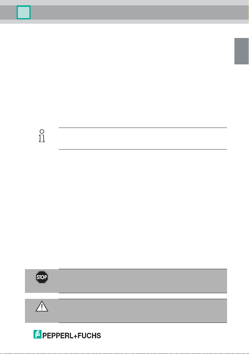
The SLCT safety light curtain consists of a transmitter unit and receiver unit. The
protection field is formed by infrared light beams sent from the transmitter unit to
the receiver unit. The offset between the individual light beams determines the
minimum obstacle size (14 mm, 30 mm, 60 mm, or 90 mm) that can be reliably
detected in the entire protection field range.
The transmitter unit contains a certain number of transmitter diodes that emit
protective beams. The number of transmitter diodes is determined by the
protection field height and the size of the obstacle. The function mode A/B
enables the use of 2 adjacent safety light curtains.
The receiver unit detects the transmission beams, controls the 2 OSSD (Output
Signal Switching Devices) safety outputs and carries out tests to ensure safety.
In addition to the displays behind the front panel of the receiver unit, there is also a
PNP output, which indicates operational readiness, a dirty lens, or fault states. If
an internal fault occurs in the receiver unit, this output switches on and off at a
frequency of 5 Hz. If an external fault occurs, this output switches on and off at a
frequency of 1 Hz. If the received signal is too weak (e.g., due to a dirty lens), the
output switches on and off at a frequency of 2.5 Hz.
The test input on the transmitter unit initiates a test sequence. Activate the input by
applying 24 VDC to the input for a defined time span.
The relay monitor (RM) and restart (RI) inputs allow monitoring of the switching
elements connected externally to the OSSDs and activation of the startup/restart
interlock function.
271695 2020-02
EN-7
SLCT* and SLCT*/35 safety light curtains
EN
Transmitter unit
24 V supply 24 V supply
OSSDs
Status / Select RI-RM
Restart Interlock (RI)
Relay Monitor (RM)
Beam Code A/B
Protection
Receiver unit
Test
Beam Code A/B
Product Description
8-EN
Figure 3.1 Schematic diagram of a detection device
Product features
■
Type 4 ESPE in accordance with IEC/EN 61496-1
■
Self-testing
■
Obstacle size, depending on type, 14 mm, 30 mm, 60 mm, 90 mm
■
Protection field heights up to 1200 mm (SCLT14)
■
Protection field heights up to 2400 mm (SLCT30, SLCT60, SLTS90)
■
Protection field grids 100 mm (SLCT14, SLCT30)
■
Protection field grids 300 mm (SLCT60, SLCT90)
■
Selectable startup/restart interlock
■
Selectable relay monitor
■
Simple layout
■
2 OSSDs
Further information about the product
The following information about the SLCT series is provided in the appendix at the
end of this document:
Technical data: .
Available profile lengths/dimensions: see chapter 8.2.
271695 2020-02
SLCT* and SLCT*/35 safety light curtains
EN
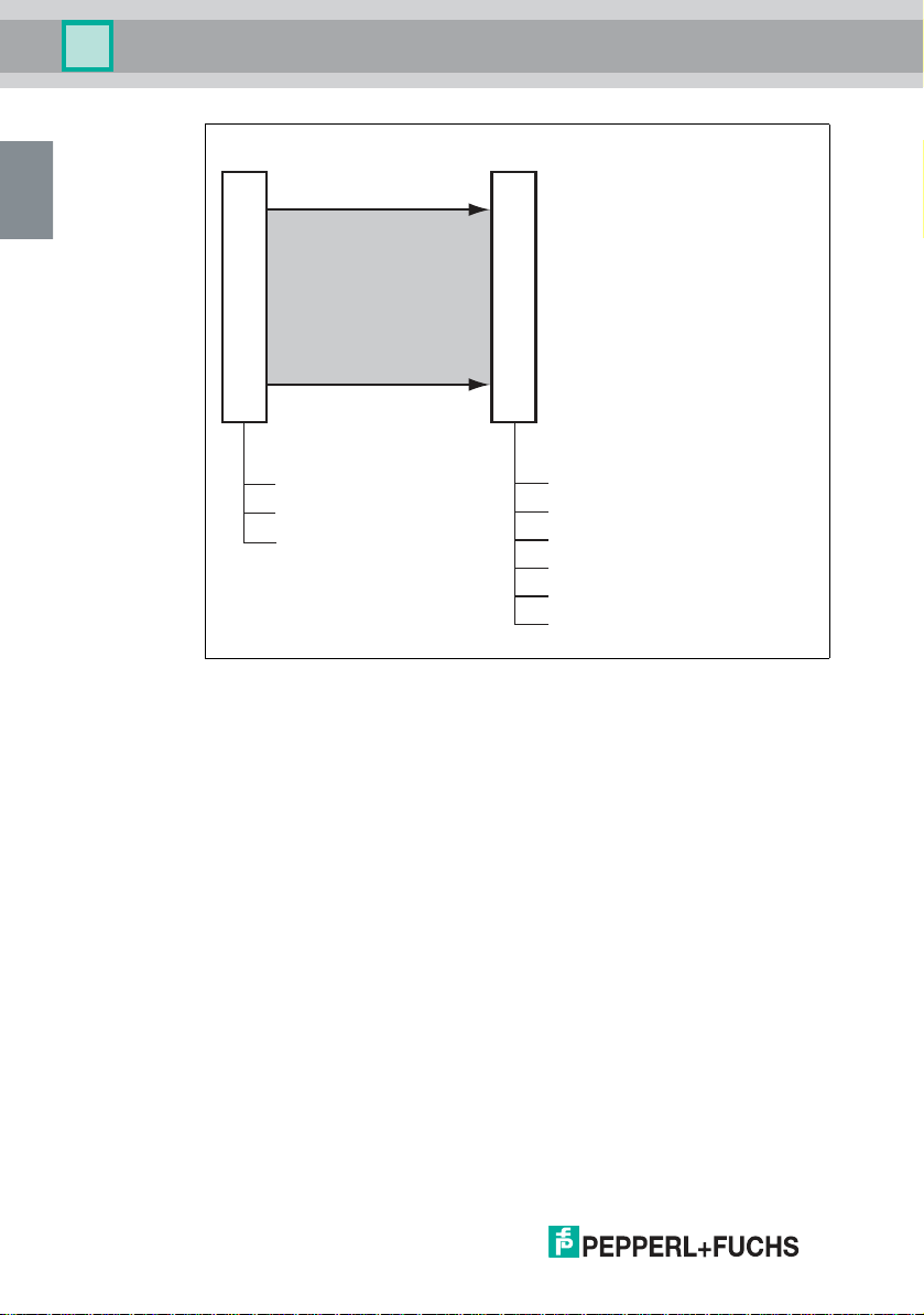
1 Power green
2 Mode A/B, Status yellow
3 OSSD OFF red
4 OSSD ON green
5 Restart/Status yellow
6 Mode A/B yellow
Transmitter
Receiver
1
2
3
5
4
6
1
Product Description
Dimensional drawings: see chapter 8.3.
Product characteristics by type code: see chapter 8.4.
Available accessories: see chapter 8.6.
3.2 Indicators and Operating Controls
The transmitter has two LEDs to display its operating status.
The receiver has five LEDs to display its operating status.
Figure 3.2 Displays on the transmitter and receiver units
No. Designation LED Color Meaning
1 Power LED Green Transmitter and receiver units operating
2 A/B mode,
status
3 OSSD OFF Red OSSDs switched off
4 OSSD ON Green OSSDs switched on
5 Restart/status Yellow On: protection field free: system ready to
6 Mode A/B Yellow Off: mode A
271695 2020-02
Yellow Indicator flashing at 1 Hz: testing time
exceeded
or A/B mode input level change
Indicator flashing at 5 Hz: internal fault
start
Indicator flashing at 1 Hz: external fault
Indicator flashing at 2.5 Hz: insufficient
functional reserve
Indicator flashing at 5 Hz: internal fault
On: mode B
EN-9
SLCT* and SLCT*/35 safety light curtains
EN
1
3
4
2
1
4
6
7
8
53
2
Product Description
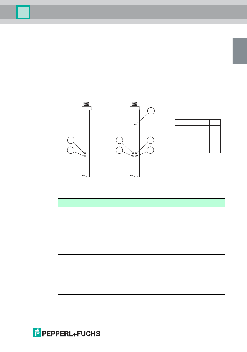
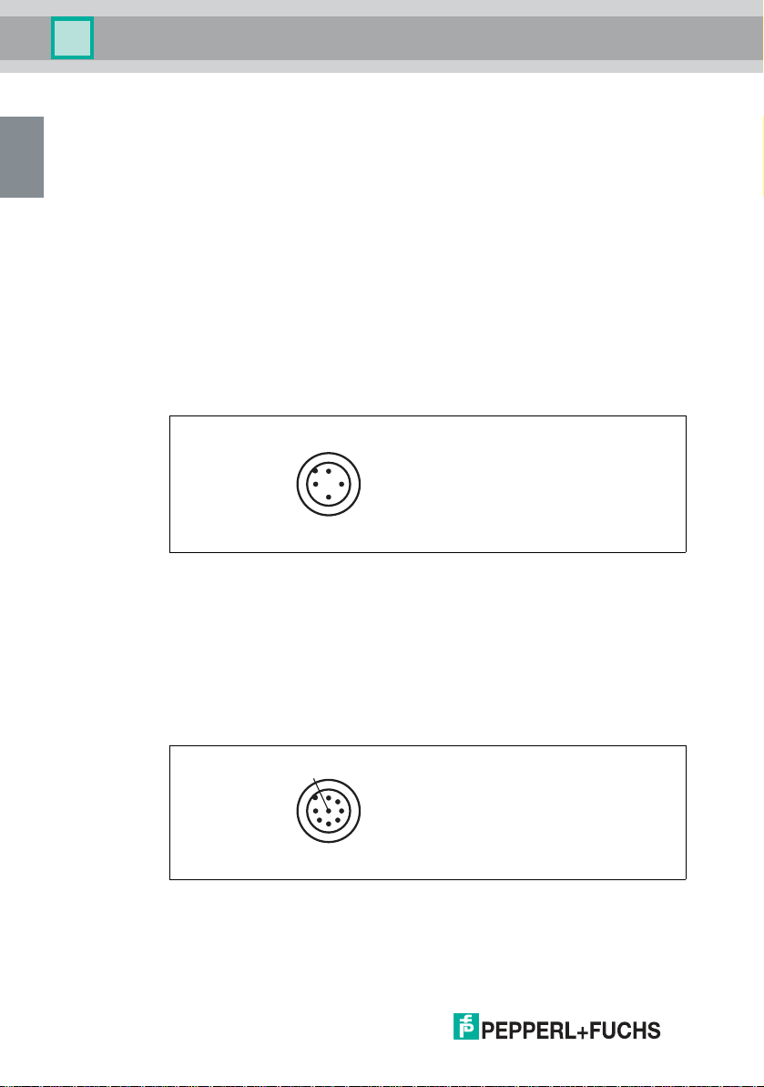
3.3 Interfaces and Connections
The electrical connections of the safety light curtain are made using M12 plug-in
connectors. The transmitter has a 4-pin connector and the receiver an 8-pin plugin connector.
Connect the power supply and, depending on the application, the test signal to
the transmitter unit. The mode can also be selected via the A/B mode input.
Connect the power supply, the fail-safe outputs (OSSD), the status/select output
and the inputs for the startup enable, relay monitor and A/B mode to the receiver
unit.
The housing profile is connected internally with approx. 2.3 MOhm// 33 nF each at
+24 V and 0 V. Internal varistors limit any surges that occur at approx. 85 V. A
separate grounding or connection between the housing and functional ground is
not required.
Transmitter
10-EN
Figure 3.3 Pin assignment transmitter unit
1 24 V DC
2 Mode A/B
3 0 V DC
4 Test
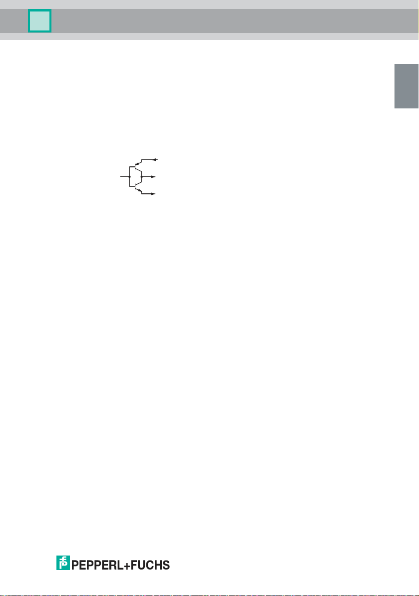
Receiver
Figure 3.4 Pin assignment receiver unit
1 Restart Interlock (RI)
2 24 V DC
271695 2020-02
SLCT* and SLCT*/35 safety light curtains
EN
0 V
24 V
OSSD 1/2
Product Description
3 Relaismonitor (RM)
4 Status / Select RI-RM
5 OSSD 1
6 OSSD 2
7 0 V DC
8 Mode A/B
3.4 Scope of Delivery
The scope of delivery includes:
Scope of delivery: transmitter
■
Transmitter
Scope of delivery: receiver
■
Receiver
■
I/O Manual
■
Test rod
Bracket and cable are not included in the scope of delivery. Visit www.pepperlfuchs.com for a selection of compatible fixing brackets and recommended cables.
271695 2020-02
EN-11
SLCT* and SLCT*/35 safety light curtains
EN
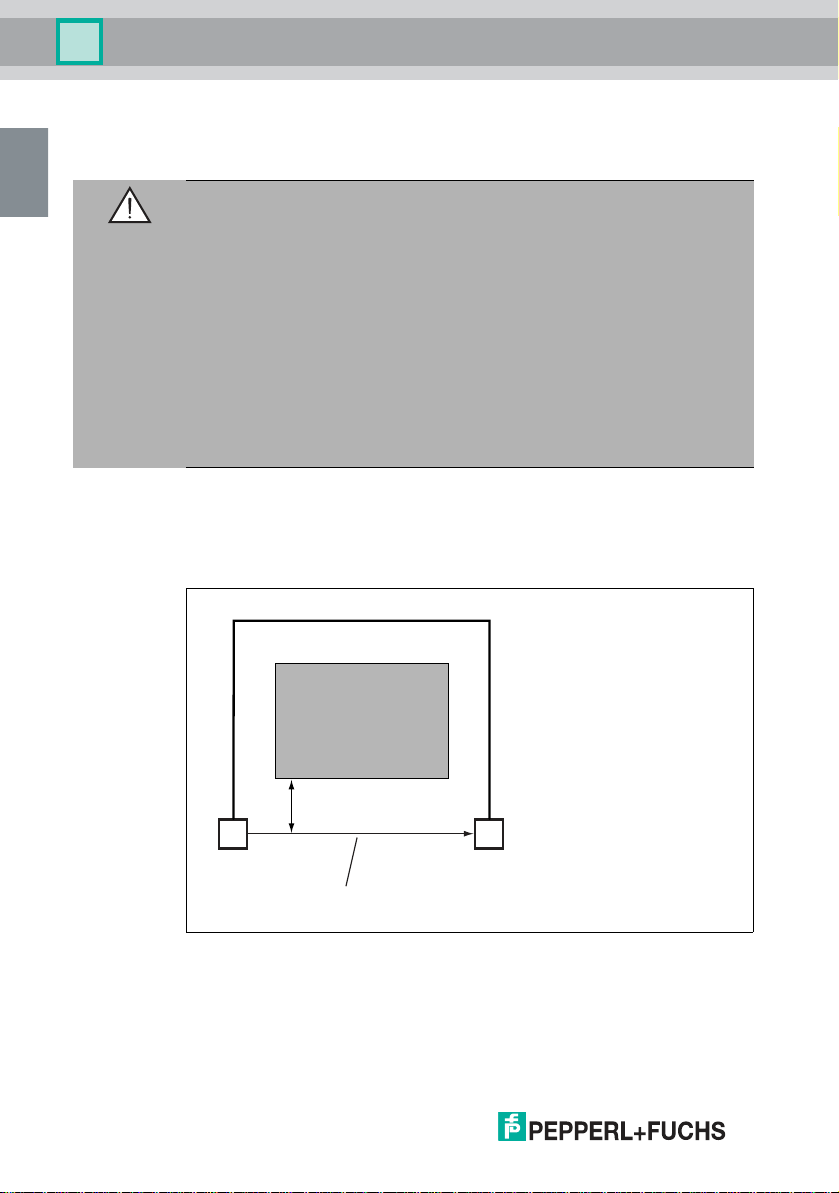
Danger zone
Minimum interval S
Sending unit
Protective field
Receiving unit
Installation
4 Installation
4.1 Planning and Preparation
Warning!
Danger to life due to ineffective protective equipment
Improper or incorrect alignment, fixing, and connection to machine control can
impair the effectiveness of the protective function.
■
Note the applicable standards, guidelines, and legal regulations for the
equipment of machine and plants with protective equipment.
■
Position the protective equipment to prevent persons from being able to
reach or walk behind it, climb over or under, or otherwise bypass the
equipment in any way.
■
Use appropriate safety distances to take into account the response times
and lag times of the components in the safety chain.
■
Secure the protective equipment against manipulation or deliberate
deactivation.
Safety distance
A minimum distance must be maintained between the protection field and the
danger zone to ensure potentially dangerous movements are brought to a stop
before contact with a person is possible.
12-EN
Figure 4.1 Minimum distance between protection field and hazardous area
This distance is calculated from the lag time of the machine, the response time of
the safety system, and the speed of movement of the person entering the
hazardous area (ISO/EN 13855).
271695 2020-02
SLCT* and SLCT*/35 safety light curtains
EN
Installation
To comply with the necessary distances in the event that the protection field
spreads, please refer to Table 1 of ISO/EN 13855 to check the minimum distance
for a vertically positioned protection field. If you read the value 0 from the table,
you can determine the minimum distance with the following formula:
S = K x T + C
Where, for a protection field aligned vertically to the hazardous area:
S Minimum safety distance in mm,
K Constant in mm/s for the speed of approach, based on the detection
T Total response time of the protective equipment in s (T = t1 +t2)
t
1
t
2
C Additional distance in mm, see table
For any arrangements other than a vertical alignment of the protection field, see also
EN ISO 13855.
i.e. the distance between hazardous area and protection field
capacity of the sensor
Response time of the protective equipment See the table below.
Machine lag time
Number of
beams/res
olution
14 mm 30 mm 60 mm 90 mm
0 mm 128 mm 850 mm 850 mm
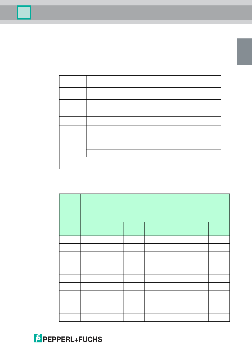
Response times of the safety light curtain
The safety light curtain response time is shown on the nameplate.
Protection
field
height
[mm] Response time [ms]
SLCT1
4-*
100 11 8 9 - - - -
200 15 10 11 - - - -
300 19 11 12 9 10 8 8
400 23 12 14 - - - -
500 26 14 16 - - - -
600 30 15 17 11 12 10 10
700 34 16 19 - - - -
800 38 17 21 - - - -
900 42 19 23 13 15 11 11
1000 46 20 25 - - - -
1100 50 21 26 - - - -
271695 2020-02
SLCT3
0-*
SLCT3
0-*/35
SLCT6
0-*
SLCT6
0-*/35
SLCT9
0-*
SLCT9
0-*/35
EN-13
SLCT* and SLCT*/35 safety light curtains
EN
Installation
Protection
field
height
[mm] Response time [ms]
SLCT1
4-*
1200 54 23 28 15 17 12 12
1300 - 24 30 - - - -
1400 - 25 32 - - - -
1500 - 26 33 17 20 14 14
1600 - 28 35 - - - -
1700 - 29 37 - - - -
1800 - 30 38 19 23 15 15
1900 - 32 40 - - - -
2000 - 33 42 - - - -
2100 - 34 43 21 25 16 16
2200 - 35 45 - - - -
2300 - 37 47 - - - -
2400 - 38 48 23 28 17 17
SLCT3
0-*
SLCT3
0-*/35
SLCT6
0-*
SLCT6
0-*/35
SLCT9
0-*
SLCT9
0-*/35
The switch-on time after beam interruption without a restart function is between
80 ms and 200 ms. The switch-on time depends on the number of protective
beams.
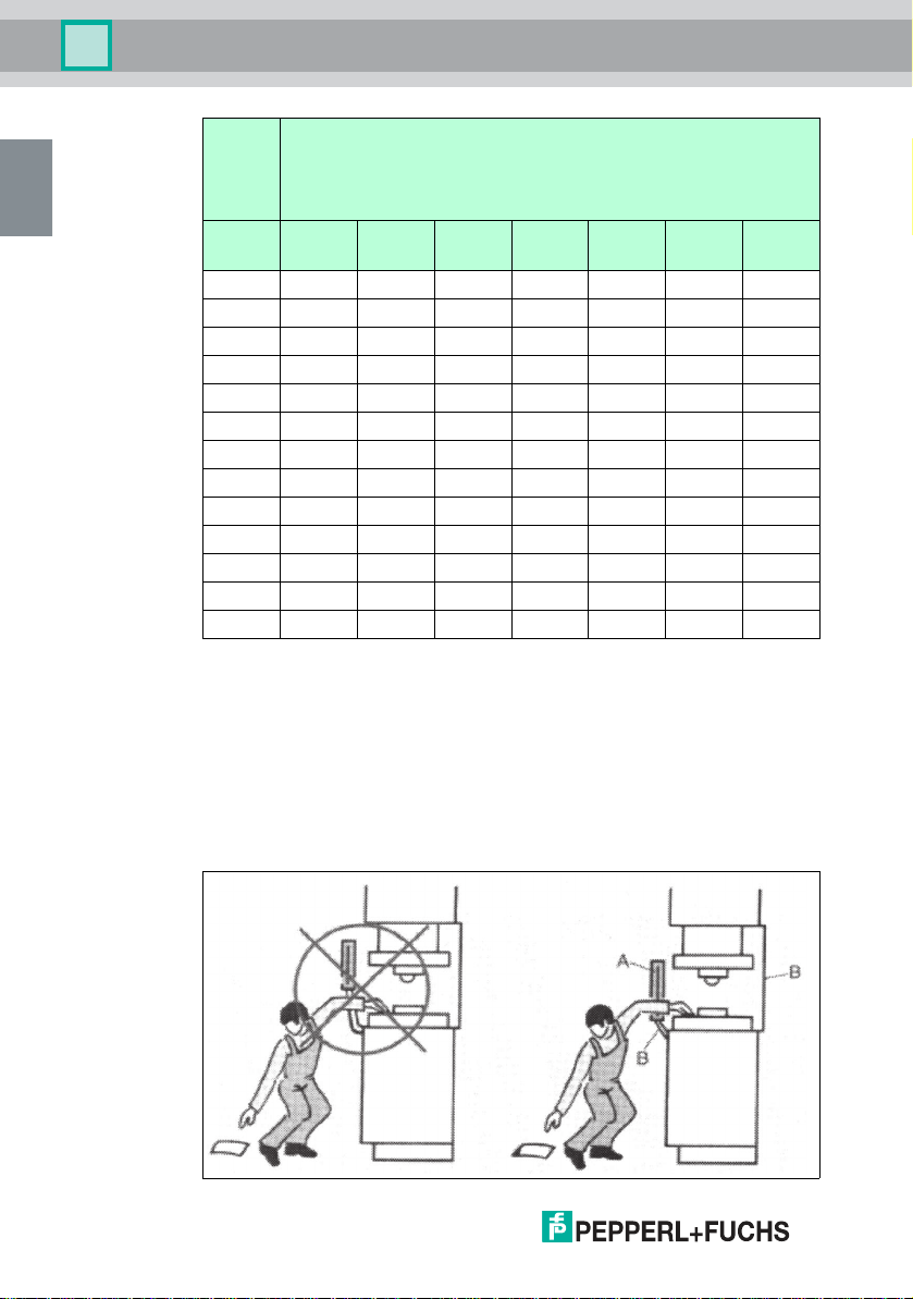
Notes on setting up safety light curtains
The protective equipment must be arranged in such a manner that it is impossible
to reach over, reach under, or walk behind the protection field. If the distance from
the protective equipment is too great, additional protective equipment must be put
in place (see illustration below).
271695 2020-02
14-EN
SLCT* and SLCT*/35 safety light curtains
EN
Installation
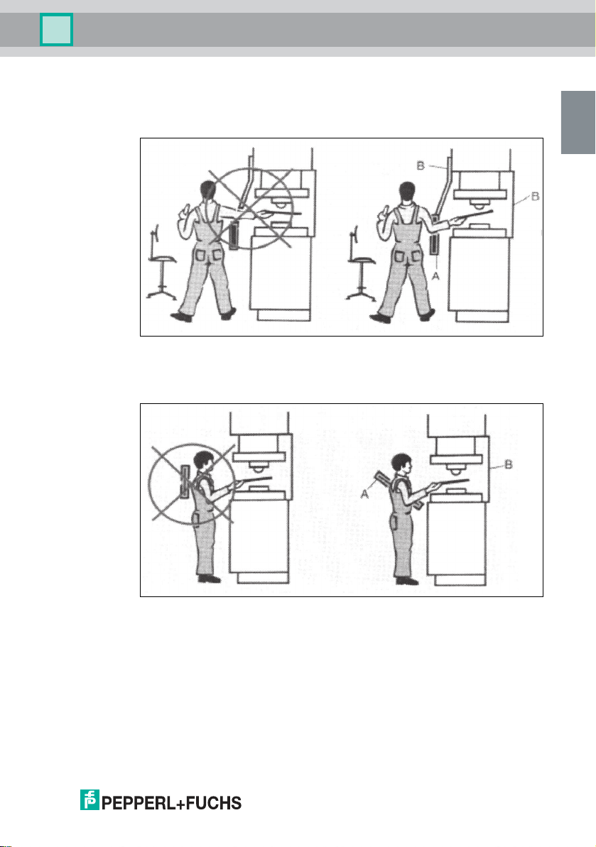
Reaching over
The operator must not be able to reach over the protection field and into the
hazardous area (A: protection field, B: mechanical protection).
Walking behind
The machine operator must not be able to walk between the light curtain and into
the danger zone (A: protection field, B: mechanical protection).
271695 2020-02
EN-15

SLCT* and SLCT*/35 safety light curtains
EN
Installation
4.2 Mounting
Warning!
Danger to life due to ineffective protective equipment
Improper or incorrect alignment, fixing, and connection to machine control can
impair the effectiveness of the protective function.
■
Check the positioning of the protective equipment and ensure that it is not
possible for persons to reach or walk behind it, climb over, under or
otherwise bypass the protective equipment.
■
Check the safety distances and the lag times of the components in the
safety chain.
■
Check that the protective equipment cannot be easily manipulated or
disabled.
Various mounting materials for mounting to machines or in the field are available
for securing the safety light curtain. See chapter 8.6.
If you are planning to install a safety light curtain with an increased detection
range, we recommend using mounting profiles for floor mounting from our
accessories range. See chapter 8.6.7.
Mounting
1. Align the transmitter and receiver units so that the two units are parallel with
one another and at the same height.
2. Align the transmitter and receiver units parallel with one another.
3. The stability alarm indicator helps with correct alignment.
When installing the safety light curtain in a hazardous area, a minimum distance
must be maintained between the protection field and the hazardous area. This
distance will ensure that movements that pose a danger to a person can be
brought to a stop before that person comes into contact with the source of danger.
The distance is calculated from the lag time of the machine, the response time of
the safety light curtain, and the speed of movement of the person entering the
hazardous area (EN ISO 13855, EN ISO 13857).
271695 2020-02
16-EN
 Loading...