

Page 1
R
Configuration Instructions
for the LB/FB Remote I/O
System
Commissioning with
SIEMENS STEP 7
Manual
Page 2

With regard to the supply of products, the current issue of the following document is applicable: The
General Terms of Delivery for Products and Services of the Electrical Industry, published by the Central
Association of the Electrical Industry (Zentralverband Elektrotechnik und Elektroindustrie (ZVEI) e.V.)
in its most recent version as well as the supplementary clause: "Expanded reservation of proprietorship"
Worldwide
Pepperl+Fuchs Group
Lilienthalstr. 200
68307 Mannheim
Germany
Phone: +49 621 776 - 0
E-mail: info@de.pepperl-fuchs.com
North American Headquarters
Pepperl+Fuchs Inc.
1600 Enterprise Parkway
Twinsburg, Ohio 44087
USA
Phone: +1 330 425-3555
E-mail: sales@us.pepperl-fuchs.com
Asia Headquarters
Pepperl+Fuchs Pte. Ltd.
P+F Building
18 Ayer Rajah Crescent
Singapore 139942
Phone: +65 6779-9091
E-mail: sales@sg.pepperl-fuchs.com
https://www.pepperl-fuchs.com
Page 3

Configuration Instructions for the LB/FB Remote I/O System
Contents
1 Introduction................................................................................................................ 4
1.1 Purpose of the Instructions .......................................................................... 4
1.2 Technical Basics ............................................................................................ 4
1.3 Registered Trademarks ................................................................................. 5
1.4 Symbols Used ................................................................................................ 5
1.5 Display conventions ...................................................................................... 5
2 User Interface Basics ................................................................................................ 6
2.1 Project view.................................................................................................... 6
2.2 Configuration View ........................................................................................7
3 Commissioning the LB/FB Remote I/O System ......................................................8
3.1 Preparation for Commissioning ................................................................... 9
3.2 Creating a New Project................................................................................ 10
3.3 Adding the Control Panel to the Project.................................................... 11
3.4 Installing the GSDML File ........................................................................... 17
3.5 Configuring the LB/FB Remote I/O System............................................... 19
3.5.1 Gateway Integration ......................................................................... 19
3.5.2 Gateway Configuration..................................................................... 20
3.5.3 Configuring the I/O Modules ............................................................ 23
3.6 Parameterizing Submodules ...................................................................... 26
3.7 Compiling and Loading the Project Configuration................................... 27
4 Diagnosis.................................................................................................................. 28
4.1 Alarms........................................................................................................... 31
5 Testing with Variable Tables.................................................................................... 33
5.1 Symbol Table ................................................................................................ 33
5.2 Variable Table ............................................................................................... 36
2020-11
3
Page 4

Configuration Instructions for the LB/FB Remote I/O System
Introduction
1 Introduction
These instructions will help you commission and configure an LB/FB remote I/O system using
the SIMATIC Manager STEP 7.
1.1 Purpose of the Instructions
These instructions describe the key functions in STEP 7 that help you commission an LB/FB
remote I/O system. Customer-specific adaptations are not described. Note that software
changes cannot always be taken into account, meaning that deviations in the description may
occur.
Note
For more information about STEP 7, refer to the corresponding online Help or documentation.
Commissioning involves the integration of the LB/FB remote I/O system in a PROFINET network. STEP 7 is used for configuration, then parameterization of the LB/FB remote I/O system
takes place.
The hardware configuration is an offline process that is completed without a connection to the
control panel (PLC). In STEP 7, a project is created and the LB/FB remote I/O system is configured. The selection of the gateway and the I/O modules from the hardware catalog enables the
exact structure of the LB/FB remote I/O system to be replicated in the software project. In the
configuration table, each I/O module is automatically assigned an address. When the automation system starts up, the target configuration created with STEP 7 is compared with the actual
configuration. Any errors can thus be detected and reported immediately.
After configuration, the LB/FB remote I/O system is parameterized. Parameterization involves
setting the device characteristics such as the addresses and stipulating the communication
characteristics. The I/Q addresses are used, for example, to define where each binary or analog signal can be read in or out.
When device configuration is complete, the configuration data is compiled in a format that the
control panel can understand and loaded into the control panel. You can use variable tables to
save different test environments. You can then reproduce tests and process monitoring multiple
times during commissioning or for service purposes.
1.2 Technical Basics
The plant operator is responsible for planning, commissioning, and operation.
Only trained and qualified personnel may commission and operate the product. The trained
and qualified personnel must have read and understood the instructions and the other documentation.
The documentation comprises the following parts:
• These instructions
• Datasheets
• LB/FB remote I/O system hardware manual
4
2020-11
Page 5
Configuration Instructions for the LB/FB Remote I/O System
Introduction
The documentation may also comprise the following parts, if applicable:
• EU-type examination certificate
• EU declaration of conformity
• Attestation of conformity
• Certificates
• Control drawings
• Instruction manual
• Other documents
1.3 Registered Trademarks
PROFINET®: trademark of PROFIBUS Nutzerorganisation e.V. (PNO)
SIMATIC, STEP®: trademark of SIEMENS AG
1.4 Symbols Used
Notices in these instructions are indicated by symbols. The safety notices begin with signal
words to indicate the severity of the hazard.
Warning messages
Caution!
This symbol indicates a possible fault.
Non-observance could interrupt the device and any connected systems and plants, or result in
their complete failure.
Information messages
Note
This symbol brings important information to your attention.
Action
This symbol indicates a paragraph with instructions. You are prompted to perform an action or
a sequence of actions.
1.5 Display conventions
Note
Graphical illustrations in these instructions are provided to aid basic understanding, and may
deviate from the actual design.
Note
These instructions refer to the English language version of the STEP 7 configuration software.
Other language versions usually apply other names for the program calls, function calls, and
menu items referred to in these instructions.
2020-11
5
Page 6
Configuration Instructions for the LB/FB Remote I/O System
1 2
User Interface Basics
2 User Interface Basics
Several views are available in STEP 7 for your automation project. The views relevant for commissioning are:
• Project view
• Configuration View
For further information on the views, refer to the Siemens AG user documentation.
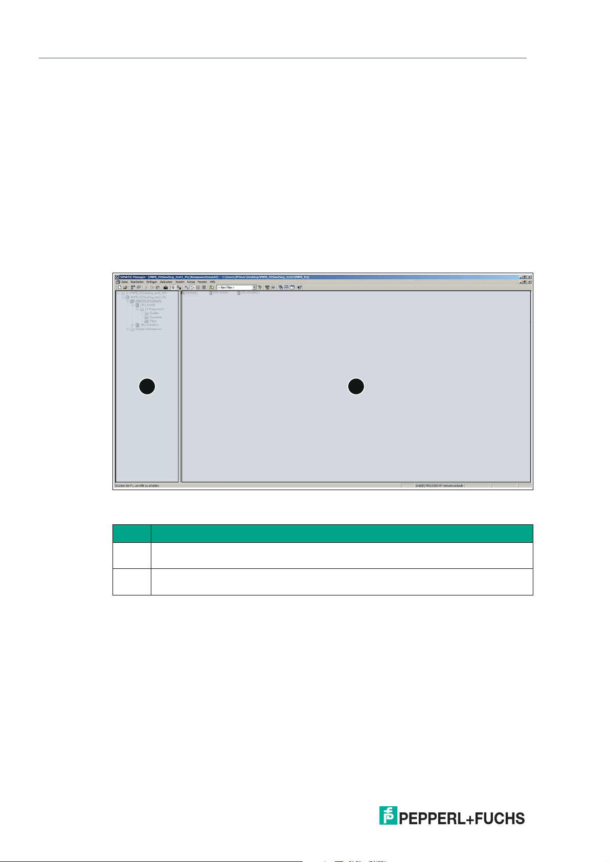
2.1 Project view
The project view is divided into two parts. The left-hand side of the window (1) displays the project tree. The right-hand side of the window (2) displays the contents of the object selected in
the project tree in the selected view (large icons, small icons, list, or details). At the top of the
project tree is your project.
Figure 2.1 Layout of the project view
Item Description
1 Project tree: the project tree displays the project with the modules that have already
been positioned.
2 Project window: the project window displays the objects that can be processed using
the selected action.
2020-11
6
Page 7
Configuration Instructions for the LB/FB Remote I/O System
1
2
3
User Interface Basics
2.2 Configuration View
The configuration view (HW Config) is an object-oriented view with several windows.
The figure below is a schematic depiction of the configuration view windows. Different content
is displayed in the different windows, as explained below.
Figure 2.2 Configuration view layout
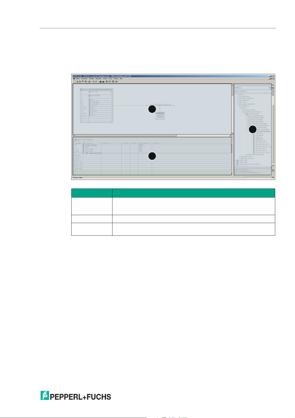
Item Description
1 Station window: the station window is used to configure the automation
2 Hardware catalog: the hardware catalog shows the available modules.
3 Detail window: the detail window displays additional information about the
system hardware, create the user program, and carry out project planning
for the hardware.
object selected in the station window or an action that has been performed.
2020-11
7
Page 8

Configuration Instructions for the LB/FB Remote I/O System
Commissioning the LB/FB Remote I/O System
3 Commissioning the LB/FB Remote I/O System
Commissioning involves the integration of an LB/FB remote I/O system into a PROFINET network and its configuration. Commissioning also involves compiling the project configuration
and transferring it to the control panel.
The following hardware components of the LB/FB remote I/O system are relevant to commissioning with STEP 7:
• Gateway
• I/O modules
The hardware components must be replicated in the project to configure the LB/FB remote I/O
system.
The gateway is the component that communicates with the control panel. The properties must
be defined to be able to configure the gateway. These properties include the device name and
the IP address.
During parameterization of the channels, the measurement behavior of the I/O modules that
process input signals is defined. At the same time, the behavior of the I/O modules that emit
output signals is defined. In STEP 7, the channels are the submodules. They are available in
the hardware catalog under the I/O modules.
To commission the LB/FB remote I/O system, perform the following steps:
• Preparation for commissioning
• Create the project
• Set up the control system
• Install the GSDML file
• Configure/parameterize the LB/FB remote I/O system
• Compile a project configuration
• Transfer a project configuration
• Check the connection
A description of how to perform the individual steps is provided on the following pages.
Note
The illustrations and information contained in this description relate to the following variants:
• Siemens SIMATIC S7 control panel (PLC/CPU)
• Siemens STEP 7 configuration software
• GSDML file for the LB/FB remote I/O system
Information about other variants can be found in the technical documentation of the control
panel and the associated software.
2020-11
8
Page 9

Configuration Instructions for the LB/FB Remote I/O System
Commissioning the LB/FB Remote I/O System
3.1 Preparation for Commissioning
It is necessary to plan the commissioning of an LB/FB remote I/O system beforehand. Planning
ensures that all files and information are available to enable efficient commissioning.
You will need the following files and information for commissioning:
GSDML file
A device description file (GSDML file) is required to use the LB/FB remote I/O system. The current GSDML file can be downloaded from our website: www.pepperl-fuchs.com. Enter the
product name or item number in the Product/Keyword search box and click on Search.
Select your product from the list of search results and click on the Software tab in the product
information list. A list of all available downloads is displayed.
The installation of the GSDML file is explained in chapter 3.4.
IP Address
When assigning the IP address, observe fundamental addressing rules, e.g., regarding the use
of private or public address areas. Check that the IP address can be used in your automation
network (no duplicate address assignment, etc.).
When assigning an address for the gateway or the LB/FB remote I/O system, the following IP
address variants are available:
• Dynamic IP address assigned via DHCP (DHCP default setting set to "on")
• Static, customer-specific, or customer-configurable IP address
IP address assignment is described in chapter 3.5.2.
Gateway name
Each PROFINET device is identified via its "Device Name." The gateway must have a unique
name before it can be addressed by the control panel.
The following rules must be observed when using the PROFINET specification for the PROFINET device name.
• The device name must not exceed 240 characters. Permitted characters:
• Letter "a" to "z,"
• Digits "0" to "9,"
• Hyphen or period
• A name component within the device name—i.e., a data string between two peri-
ods—must not exceed 63 characters.
• The device name must not begin or end with a hyphen.
• The device name must not begin with the character string "port-xyz" (x, y, z = 0 to 9).
• The device name must not have the form n.n.n.n (n = 0 to 9).
Gateway name assignment is described in chapter 3.5.2.
2020-11
9
Page 10
Configuration Instructions for the LB/FB Remote I/O System
1
2
Commissioning the LB/FB Remote I/O System
3.2 Creating a New Project
After you have planned the commissioning, create a project. The control panel and hardware
components of the LB/FB remote I/O system are replicated in the project.
Creating the project
To create a project, proceed as follows:
1.
Start the SIMATIC Manager.
2.
Select File > New Project.
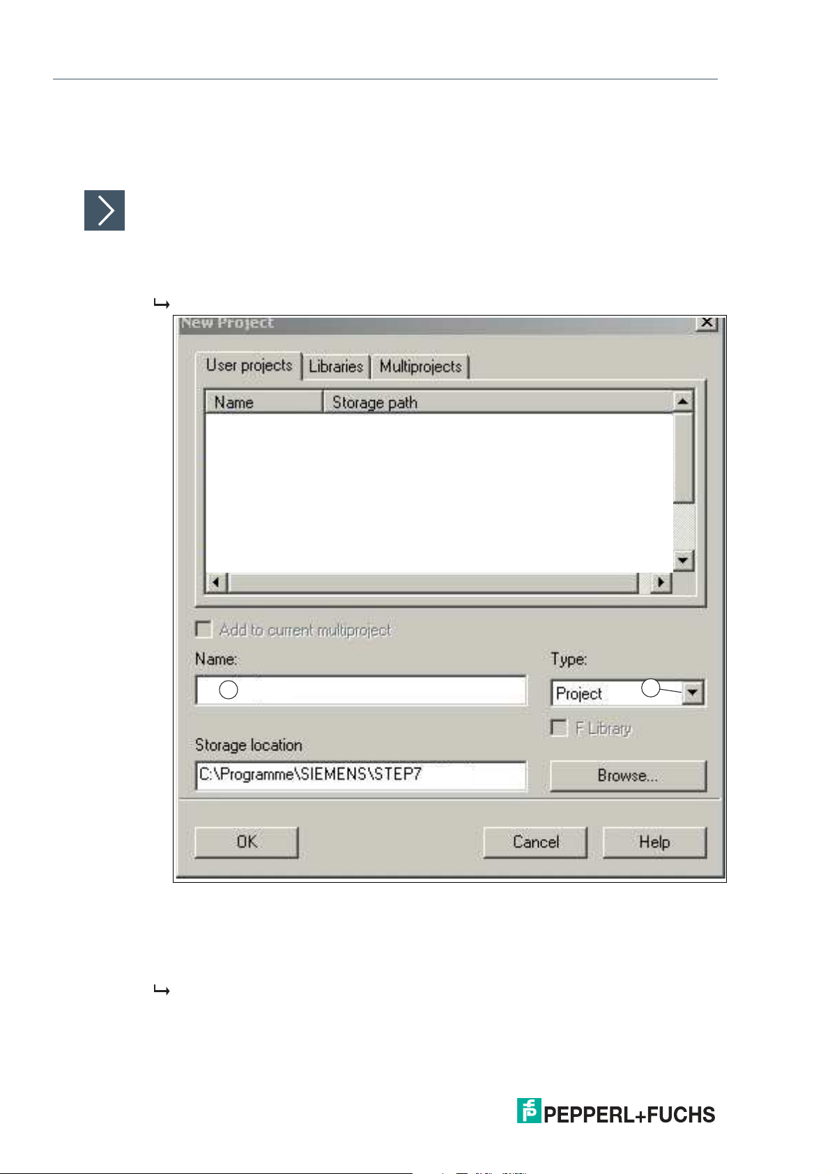
The New Project window opens.
10
Figure 3.1 New Project window
3.
In the Name input field (1), enter a name for your project.
4.
From the Type drop-down list (2), select Project.
5.
Click on OK to confirm your selection.
The project view opens.
2020-11
Page 11
Configuration Instructions for the LB/FB Remote I/O System
1
2
3
Commissioning the LB/FB Remote I/O System
Figure 3.2 SIMATIC Manager: project view
3.3 Adding the Control Panel to the Project
A control panel is an electronic assembly used in automation technology for open-loop and
closed-loop control tasks. The control panel reads process input data and controls the outputs
accordingly.
The control panel communicates with the gateway and is required for commissioning.
Integrating the control panel
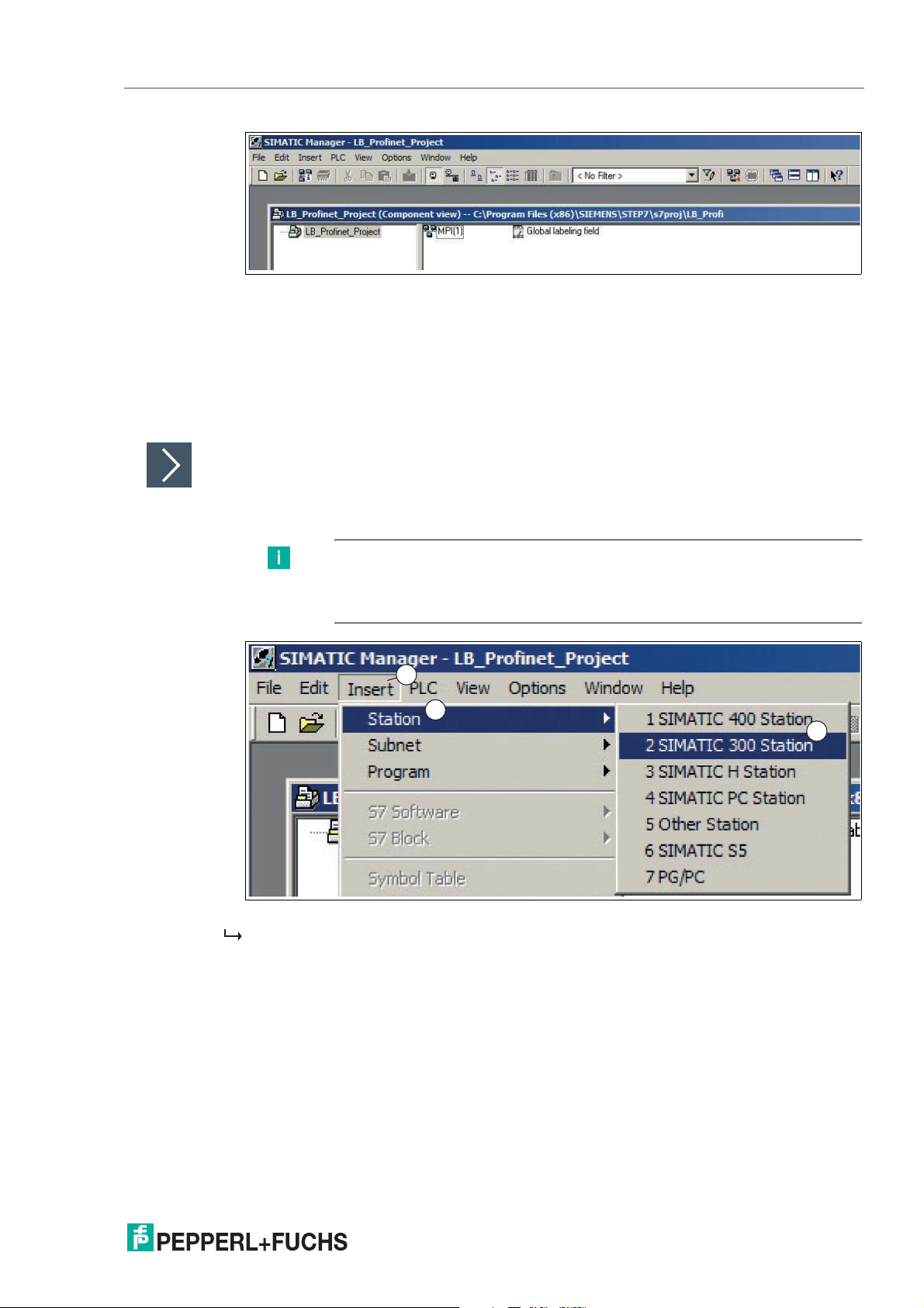
The following steps require the station window to be open. To set up the control system, proceed as follows:
1.
Select Insert (1) > Station (2) > 1 SIMATIC 300 Station (3).
Note
This configuration example uses the SIMATIC 300 station. This may vary
depending on your automation project. Please select the control panel that you
are using at this point.
Figure 3.3 Selecting the control panel
A placeholder for the selected control system is added to the project tree.
2.
In the project tree, select the placeholder for the control system (1).
2020-11
11
Page 12
Configuration Instructions for the LB/FB Remote I/O System
1
2
1
2
3
Commissioning the LB/FB Remote I/O System
Figure 3.4 Open HW Config
3.
In the project window, double-click on Hardware (2).
The HW Config configuration view opens.
Note
The components of the control system can be found in the hardware catalog
on the right-hand side of the window in the configuration view. If the hardware
catalog is not automatically displayed, click on the view catalog icon in the
menu bar .
Configure the control system according to your requirements. To do this, drag
the required components from the hardware catalog into the station window.
The following configuration example is used to promote general understanding
and may differ from your configuration.
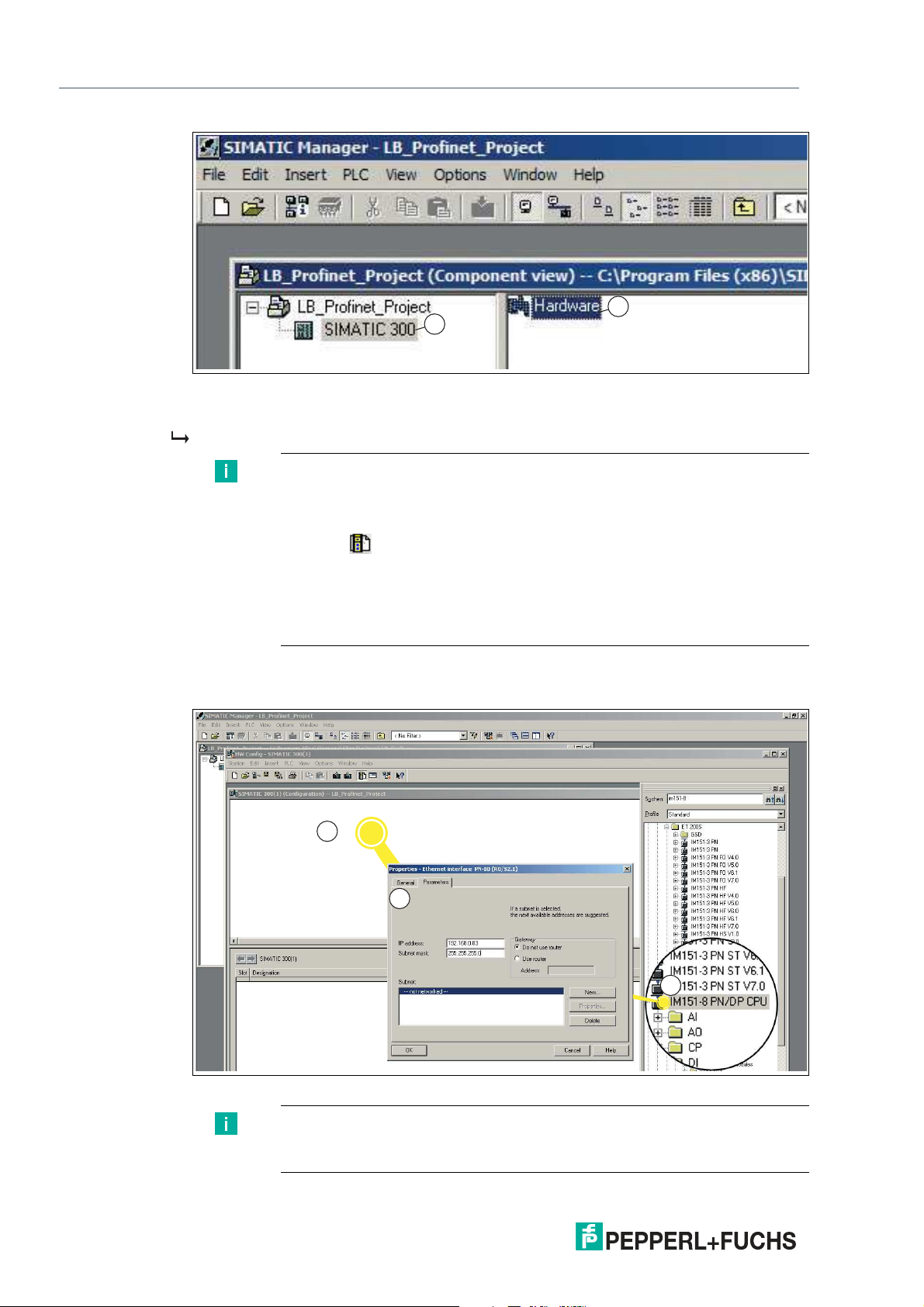
4.
Select your CPU from the hardware catalog window (1). In this configuration example, it is an
IM151-8 PN/DP CPU for ET200S.
Figure 3.5 Hardware catalog
Note
Check the version of the operating system for your CPU and select that exact
version from the hardware catalog window.
2020-11
12
Page 13

Configuration Instructions for the LB/FB Remote I/O System
1
2
3
Commissioning the LB/FB Remote I/O System
5.
Drag and drop the CPU into the station window (2). You can also double-click on the CPU in the
hardware catalog window.
The Properties - Ethernet interface PN-IO (R0/S2.2) window (3) opens.
6.
In the properties window, enter the IP address (1) and the subnet mask (2).
Note
If you work in an Ethernet company network, you will usually receive the
address from your network administrator.
Figure 3.6 IP address and subnet mask
The control panel appears in the form of a small configuration table (1) in the upper part of
the station window. The lower part of the station window displays the detail view of the control panel.
7.
In the configuration table, double-click on the X1 PN-IO interface (1).
The properties window for the X1 PROFINET interface opens.
8.
Click on New... (2).
2020-11
13
Page 14

Configuration Instructions for the LB/FB Remote I/O System
2
1
3
2
1
Commissioning the LB/FB Remote I/O System
The New subnet Industrial Ethernet properties window opens.
9.
Assign a name (1) for a new subnet Industrial Ethernet. Click on OK (2) to confirm your input.
Figure 3.7 Subnet Industrial Ethernet
The properties window for the subnet Industrial Ethernet closes.
10.
In the Properties - Ethernet interface PN-IO (R0/S2.2) window, click on OK (3).
2020-11
14
Page 15

Configuration Instructions for the LB/FB Remote I/O System
1
Commissioning the LB/FB Remote I/O System
The properties window for the X1 PROFINET interface closes.
Note
In HW Config, you can set further options for the PROFINET interface as
required.
Double-click on the X1 PROFINET interface in HW Config to access the
settings.
Switch to the Properties tab if necessary. Here you can configure individual
network settings as required. The "automatic setting" is selected by default. In
normal situations, this guarantees problem-free communication. If
communication problems occur (for example, if connections cannot be
established or frequent network disruptions occur), this may be because the
selected network setting or the automatic network setting is not appropriate.
Select a network setting that is suitable for your network configuration.
11.
Select the menu command Station > Save and compile
The hardware configuration is compiled and saved.
12.
Select Target system > Load in module.
The dialog box for selecting the target module is displayed. The CPU is already marked as
the target module.
Figure 3.8 Dialog box for selecting the target module
13.
Click on OK (1).
The Select Node Address dialog box is displayed. The CPU is not yet displayed under
"Available Nodes."
2020-11
15
Page 16

Configuration Instructions for the LB/FB Remote I/O System
3
2
1
1
Commissioning the LB/FB Remote I/O System
Figure 3.9 Dialog box for selecting the node address
14.
Click on View (1).
The programming unit reads the MAC ID and displays it in the dialog box.
15.
Select the line with the MAC ID of the CPU (2) and confirm with OK (3).
The Download message window opens.
Figure 3.10 Download message window
16.
Confirm the message by clicking on Yes (1).
An IP address is assigned to the CPU and the configuration is loaded.
2020-11
16
Page 17

Configuration Instructions for the LB/FB Remote I/O System
1
2
Commissioning the LB/FB Remote I/O System
17.
Close HW Config via Station > Finish and answer Yes when you are prompted to save.
HW Config closes. In the SIMATIC Manager, the CPU is now visible in the station.
3.4 Installing the GSDML File
The device description file (GSDML file) is required to use the LB/FB remote I/O system. The
GSDML file can be downloaded from our website: www.pepperl-fuchs.com. Enter the product
name or item number in the Product/Keyword search box and click on Search. Select your
product from the list of search results and click on the Software tab in the product information
list. A list of all available downloads is displayed.
Installing the GSDML file
The GSDML file contains all the information required to configure the LB/FB remote I/O system
using the STEP 7 configuration software. This makes it possible to replicate the gateway and
the I/O modules in the project. To install the GSDML file, proceed as follows:
1.
Open the configuration view (HW Config).
2.
Close all open stations in the station window. To do this, select Station > Close.
3.
Select Options (1) > Install GSD file (2).
Figure 3.11 GSDML file
The Install GSD Files window opens.
4.
Click on Browse (1) to search for the GSDML file on your storage medium.
2020-11
17
Page 18

Configuration Instructions for the LB/FB Remote I/O System
1
3
2
Commissioning the LB/FB Remote I/O System
Figure 3.12 Search for GSDML file
5.
Select the folder containing the GSDML file.
All GSDML files in the selected folder are displayed in the Install GSD Files window.
6.
In the selection window, select the required GSDML file (2).
7.
Click on Install (3).
The system tells you that the installation of the GSDML file cannot be undone.
8.
Click on Yes.
Installation of the GSDML file begins.
9.
Click on OK to close the information window. The device data is loaded in the hardware
catalog.
10.
Open the previously closed SIMATIC station. To do this, select your SIMATIC station from the
Station menu.
2020-11
18
Page 19

Configuration Instructions for the LB/FB Remote I/O System
1
2
Commissioning the LB/FB Remote I/O System
3.5 Configuring the LB/FB Remote I/O System
The hardware components of the LB/FB remote I/O system are replicated in the project to guarantee communication between the control panel and the LB/FB remote I/O system.
Note
Ensure that the project is in offline mode. Otherwise, it will not be possible to replicate the
hardware components.
Note
Please note: This description cannot cover all details of the PROFINET communication.
3.5.1 Gateway Integration
The gateway forms part of the LB/FB remote I/O system and handles communication with the
control panel.
Integrating the gateway
To integrate the gateway, proceed as follows:
Select the gateway (1) from the hardware catalog and drag and drop it into the station window
(2).
Figure 3.13 Integrating the gateway
The gateway appears in the station window and is connected to the control panel.
2020-11
19
Page 20

Configuration Instructions for the LB/FB Remote I/O System
Commissioning the LB/FB Remote I/O System
3.5.2 Gateway Configuration
The control panel generally assigns the IP address automatically and assigns it to the gateway
on the basis of the gateway name. If it is a standalone network, you can use the default IP
address and subnet mask specified by the control panel. If the network is a part of an existing
Ethernet company network, obtain the IP address and subnet mask from your network administrator.
Gateway name
In the PROFINET IO system, each device has a unique device name (symbolic name). In the
configuration program, the device name can be automatically assigned using the device name
from the GSDML file and a sequential number. The gateway can only be addressed by the
control panel after the name has been assigned via the configuration software e.g., for transferring project planning data or for exchanging user data in cyclic operation.
IP addresses
Each PROFINET device must have an IP network address to establish an application relationship. There are a number of ways to manage these network IP addresses:
• Configuration during project planning
During project planning of the LB/FB remote I/O system, a range of network addresses is
made available to the configuration program. The configuration program assigns an IP
address to the control panel and the gateway. During system configuration, the control
panel receives a list of IP addresses and assigns these to the individual gateways during
initialization of the application relationships.
• Management by a DHCP server
If the IP addresses are managed by a DHCP server, the IP addresses are requested independently by the individual gateways. When the application relationship is established,
the control panel addresses the gateway using its name to access the IP address
assigned to it.
• Fixed setting
In principle, the network administrator can manage IP addresses manually using the DCP
(Dynamic Configuration Protocol) or a local interface on the field device. This approach
makes it difficult to replace devices as the IP addresses always have to be reentered.
20
2020-11
Page 21

Configuration Instructions for the LB/FB Remote I/O System
1
2
3
4
5
6
7
Commissioning the LB/FB Remote I/O System
Gateway number
In addition to the gateway name, STEP 7 assigns a device number starting with "1" when the
gateway is plugged in. This device number can be used to identify the gateway in the user program. Unlike the gateway number, the gateway name is not visible in the user program.
Configuring the gateway
The control panel generally assigns the IP address automatically and assigns it to the gateway
on the basis of the gateway name. If it is a standalone network, you can use the default IP
address and subnet mask specified by the control panel. If the network is a part of an existing
Ethernet company network, obtain the IP address and subnet mask from your network administrator. To configure the gateway, proceed as follows:
1.
In the station window, double-click on the symbol name for the gateway (1).
Figure 3.14 Example: Properties dialog LB8122* (applies analog to FB8222*)
The Properties - LB-8122 window (2) of the gateway opens.
2.
In the Device name input field (3), assign the gateway an appropriate name or a user-specific
designation.
3.
In the drop-down list of the Device number field (4), select a unique device number.
4.
Ensure that the right IP address (5) is assigned.
5.
If you want to change the IP address, uncheck the Assign IP address via IO controller check
box (6) and click on Ethernet (7).
The Properties - Ethernet interface LB-8122 window (1) opens
2020-11
21
Page 22

Configuration Instructions for the LB/FB Remote I/O System
1
2
3
Commissioning the LB/FB Remote I/O System
Figure 3.15 Example: Ethernet interface property dialog LB8122* (applies analog to FB8222*)
6.
In the IP address input field (2), enter the IP address.
Note
If you establish a connection via a router, you must also enter the address of
the router.
7.
Click on OK (3) to confirm your input.
The Properties - Ethernet interface LB-8122 window closes.
8.
Click on the OK button.
The Properties - LB-8122 window of the gateway closes.
2020-11
22
Page 23

Configuration Instructions for the LB/FB Remote I/O System
8
7
6
5
4
3
2
1
I
2
4
AO
DO
P
1
3
AI
DI
LB7104A
4UIO
8
7
6
5
4
3
2
1
I
2
4
AO
DO
P
1
3
AI
DI
LB7104A
4UIO
8
7
6
5
4
3
2
1
I
2
4
AO
DO
P
1
3
AI
DI
LB7104A
4UIO
6
5
4
3
2
1
P
1
LB5101A
1DI
6
5
4
3
2
1
P
1
2
LB6101H
2DI
8
7
6
5
4
3
2
1
I
2
P
1
M
LB6116E
2DO
6
5
4
3
2
1
I
I2
P
O
I1
LB2116E
1DO/2DI
6
7
8
5
4
3
2
1
14
15
16
13
12
11
10
9
I
2
4
6
8
P
1
3
5
7
LB1109A
8DI
OK NET L1 L2
LB8122
Commissioning the LB/FB Remote I/O System
3.5.3 Configuring the I/O Modules
The I/O modules form part of the LB/FB remote I/O system. I/O modules are used to record
measured values and to output signals for process intervention purposes.
The configuration example in these instructions replicates the following hardware arrangement
of an LB/FB remote I/O system:
Figure 3.16 Sample hardware configuration with LB Remote I/O System (FB Remote I/O System
analog)
• LB8122*/FB8222* Gateway
• LB7104*/FB7204* Universal input/output (HART)
• LB7104*/FB7204* Universal input/output (HART)
• LB7104*/FB7204* Universal input/output (HART)
• LB5102*/FB5202* RTD signal converter input
• LB1109*/FB1209* Digital input
• LB2116*/FB2216* Digital output with position feedback
• LB6116*/FB6216* Digital output with shutdown input
• LB6101*/FB6301* Relay output
I/O module groups
One channel of an I/O module is represented by one submodule in STEP 7. The functions of an
I/O module can be specified by subordinating one or more submodules to an I/O module.
The I/O modules are organized by type in the hardware catalog in the Module section. The
channels of the I/O modules are organized in the hardware catalog in the Submodules section.
A distinction is made between three different I/O module groups:
• I/O modules with fixed preassigned input channels or output channels, e.g., 6x01 relay
output. The channels (submodules) of these I/O modules cannot be removed from the
device overview. The submodules of this I/O module group are not listed in the hardware
catalog.
2020-11
• I/O modules without fixed default input channels or output channels, e.g., 5x05 thermo-
couple signal converter. These I/O modules are not assigned predefined channels (submodules). The preassigned submodules can be removed from the device overview and
other submodules from the hardware catalog suitable for the I/O module can be used.
• I/O module 7x04 with unassigned input channels and output channels. You must assign
the channels (submodules) for this I/O module.
23
Page 24

Configuration Instructions for the LB/FB Remote I/O System
2
3
1
Commissioning the LB/FB Remote I/O System
Adding I/O modules
To integrate the I/O modules, proceed as follows:
Note
Important information for the integration
The I/O modules are added in the same order as they are positioned on the
backplane. The gateway is placed in slot 0 in advance. You can place your I/O
modules in slot 1 onward.
Note
In the search field (1) of the hardware catalog, you can enter the name of the
I/O module instead of navigating to the I/O module.
Note
Wide I/O modules take up two slots on the backplane. STEP 7 does not
identify wide I/O modules by itself. If you drag a wide I/O module into the
project, leave the slot below empty in the table.
24
Figure 3.17 Integrating I/O modules
1.
Open the hardware catalog.
2.
Choose your I/O modules from the hardware catalog (2) and drag and drop them into the
configuration table below the gateway (3).
Free slots have a light green background in the table.
Note
When you drag an I/O module into the configuration table, STEP 7
automatically assigns an address range to the I/O module. The address
assignment size (e.g., 2 bytes) is determined by STEP 7 using the GSDML file.
You can change the I/O addresses; see the next section.
2020-11
Page 25

Configuration Instructions for the LB/FB Remote I/O System
1
2
3
4
Commissioning the LB/FB Remote I/O System
Note
The Slot column in the configuration table represents the physical slot on the
backplane. The I address column represents the address assignment of the
input channel, and the Q address column represents the address assignment
of the output channel.
The I/O modules are automatically assigned an address range.
Changing the I/O address
1.
In the configuration table, double-click on the module name whose I/O address you wish to
change.
The Properties – ... window (1) for the selected I/O module opens.
Figure 3.18 I/O module properties window
2.
Select the Addresses tab (2).
3.
Change the Start address (3) for the inputs or outputs.
4.
Click on OK (4) to confirm the input.
The modified address is displayed in the configuration table.
2020-11
25
Page 26

Configuration Instructions for the LB/FB Remote I/O System
5
2
4
1
3
Commissioning the LB/FB Remote I/O System
3.6 Parameterizing Submodules
Parameterizing allows you to configure the behavior of the I/O modules individually. A submodule represents a channel in an I/O module and determines the function performed by an I/O
module. A distinction is made between the following variants of parameterization:
• Configure measuring behavior: During parameterization of the submodules, the measur-
ing behavior of the I/O modules that process input signals is configured.
• Define measuring limits: You can define measuring limits during parameterization. If these
measuring limits are exceeded or not reached, the gateway sends an alarm to the control
panel.
• Influence output signals: The behavior of I/O modules that emit output signals is also
defined during parameterization. These output signals affect the process.
Parameterizing submodules
To parameterize a submodule, proceed as follows:
1.
Start the PROFINET hardware configuration in your configuration software.
2.
In the configuration table, double-click on a channel of an I/O module (1) that you want to
parameterize.
Figure 3.19 Parameterizing submodules
The Properties – ... window for the channel opens.
3.
Click on the Parameters tab (3).
The parameters input screen for the selected channel opens.
Note
For more information on the parameters and their properties, refer to the
software manual for the PROFINET gateway.
4.
Define the parameter values in the field of the Value column (4).
5.
Click on OK (5) to confirm the change.
2020-11
26
Page 27

Configuration Instructions for the LB/FB Remote I/O System
1
2
Commissioning the LB/FB Remote I/O System
3.7 Compiling and Loading the Project Configuration
When you have configured the LB/FB remote I/O system and parameterized the I/O modules,
compile and transfer the project configuration. During compilation, the project configuration is
converted such that it can be read by the control panel. When you transfer the product configuration, this provides the control panel with all the settings and data for data exchange.
Compiling and loading project configuration
To compile and transfer the project configuration, proceed as follows:
Figure 3.20 Compiling and transferring project configuration
1.
Save and compile the project by clicking on Compile (1).
2.
Transfer the project configuration to the CPU of the control panel by clicking on Download (2).
3.
Click OK to confirm the dialog box and confirm the following dialogs to restart the control panel
and apply the changes.
If the configuration is error-free, the settings are loaded.
2020-11
27
Page 28

Configuration Instructions for the LB/FB Remote I/O System
Diagnosis
4 Diagnosis
You can use the integrated alarm functions in STEP 7 to detect faults. The diagnostics can only
be accessed in online mode.
The gateway detects faults on the following components:
• Backplane
• Gateway
• I/O module
• Channel
• Power supply
Cyclic and acyclic data traffic
If the gateway detects a fault, it transmits fault data and diagnostic data via cyclic and acyclic
data traffic. The gateway transmits fault bits and alarm bits via cyclic data traffic. The gateway
uses the PROFINET alarm function via acyclic data traffic. Alarms are reported when events in
the LB/FB remote I/O system or in the process occur and disappear again.
The following alarm types are sent via acyclic data traffic:
• Diagnostic alarms
Diagnostic alarms relate to faults in LB/FB remote I/O system components, e.g., wire
break on one of the channels.
Diagnostic alarms are transmitted with one of the following priorities: "Fault," "Maintenance required," or "Maintenance demanded." "Fault" has the highest priority. If an event
occurs on a channel that leads to a top-priority diagnostic alarm (fault) (e.g., lead breakage), the corresponding cyclic data is automatically deemed bad via the IO Producer Status (IOPS = Bad) and can no longer be used for the control panel. In such cases, the
control panel must continue processing the faulty input data appropriately in accordance
with its substitute value strategy.
• Process alarms
Process alarms relate to measured values in the process. The limits of measuring ranges
are defined during parameterization of the channels (submodules) in STEP 7. For example, it is possible to define that the gateway should report a process alarm to the control
panel if the measured value of a temperature sensor exceeds 30 °C. For more information
about the parameterization of I/O modules, see chapter 3.6.
• Pull alarms
The gateway transmits pull alarms when an I/O module is pulled out of the backplane.
• Plug alarms
The gateway transmits plug alarms if an I/O module is plugged into the backplane.
Alarms are generated by the gateway and reported to the control panel. If the gateway reports
an alarm, the alarm is always acknowledged by the control panel. Organization blocks (OB) are
available in STEP 7 for further processing of alarms. The organization blocks are triggered by
alarms. For more information about organization blocks, refer to the Siemens AG user documentation.
If you are connecting STEP 7 to the PROFINET network, you can access diagnostic information about faults online.
28
2020-11
Page 29

Configuration Instructions for the LB/FB Remote I/O System
1
Ethernet/PROFINET
2
3
8
7
6
5
4
3
2
1
I
2
4
AO
DO
P
1
3
AI
DI
LB7104A
4UIO
8
7
6
5
4
3
2
1
I
2
4
AO
DO
P
1
3
AI
DI
LB7104A
4UIO
8
7
6
5
4
3
2
1
I
2
4
AO
DO
P
1
3
AI
DI
LB7104A
4UIO
P
LB9006C
6
5
4
3
2
1
P
1
LB5101A
1DI
6
5
4
3
2
1
P
1
2
LB6101H
2DI
8
7
6
5
4
3
2
1
I
2P1
M
LB6116E
2DO
6
5
4
3
2
1
I
I2
P
O
I1
LB2116E
1DO/2DI
6
7
8
5
4
3
2
1
14
15
16
13
12
11
10
9
I
2
4
6
8
P
1
3
5
7
LB1109A
8DI
OK NET L1 L2
LB8122
56
4
Diagnosis
The following figure illustrates cyclic and acyclic data traffic.
Figure 4.1 Diagnostic information
Item Description
1 Control panel
2 STEP 7
3 LB/FB remote I/O system
4 Gateway diagnosis
5 Cyclic data: fault bits and alarm bits
6 Acyclic data: alarms
This chapter describes only the diagnostics that are available in STEP 7.
For further information about fault bits and alarm bits in the cyclic data and the diagnostic data
that you can access in the gateway, refer to the software manual for the PROFINET gateway.
2020-11
29
Page 30

Configuration Instructions for the LB/FB Remote I/O System
Diagnosis
Identifying faults
1.
Select the menu command View > Online.
The online window of the project opens.
2.
Open your automation project to ensure that the configured programmable modules are
displayed.
3.
Determine which module is displaying a diagnostic icon that indicates a fault or a malfunction.
Note
Press the F1 key on your keyboard to open the Help page that explains the
diagnostic icons.
4.
Select the module you want to examine.
5.
Select the menu command Target system > Diagnosis/settings > Module statusto display
the module status of the LB/FB remote I/O system.
30
2020-11
Page 31

Configuration Instructions for the LB/FB Remote I/O System
Diagnosis
4.1 Alarms
Alarms are part of the acyclic data traffic and are used to report events in the process or in the
LB/FB remote I/O system. A distinction is made between the following alarm types: diagnostic,
process, pull, and plug. Diagnostic alarms are transmitted with different priorities.
The following table includes all the alarms supported by the LB/FB remote I/O system. Refer to
the software manual for the PROFINET gateway for comprehensive information on which
alarms are supported by the relevant I/O module.
Alarm Alarm type Priority Description
Line fault
(Error type
257)
Open wire
(Error type 6)
Short circuit
(Error type 1)
Roll over
(Error type
259)
Roll under
(Error type
260)
Over range
(Error type 7)
Under range
(Error type 8)
Low low alarm
(Error type
264)
Low alarm
(Error type
263)
High alarm
(Error type
262)
High high
alarm (Error
type 261)
Backplane
error (Error
type 280)
Invalid (Error
type 265)
Done
(counter)
(Error type
258)
Diagnostic alarm Fault A lead breakage or a short circuit is
Diagnostic alarm Fault A lead breakage is present.
Diagnostic alarm Fault A short circuit is present.
Process alarm – The counter limit has been reached and
Process alarm – Zero crossing of the counter value has
• Analog output:
process alarm
• Analog input:
• diagnostic alarm
• Analog output:
process alarm
• Analog input:
• diagnostic alarm
Process alarm – The measured value has fallen below
Process alarm – The measured value has fallen below
Process alarm – The measured value has exceeded the
Process alarm – The measured value has exceeded the
Diagnostic alarm Fault A fault is present on the backplane.
Diagnostic alarm Maintenance
Process alarm – The counter has reached the cyclic
Maintenance
demanded
Maintenance
demanded
required
present.
the counter is automatically reset.
taken place.
The measured value has exceeded the
upper limit of the permitted measuring
range.
The measured value has fallen below
the lower limit of the permitted
measuring range.
the limit defined in the Low Low Alarm
Limit parameter.
the limit defined in the Low Alarm Limit
parameter.
limit defined in the High Alarm Limit
parameter.
limit defined in the High High Alarm
Limit parameter.
The output data from the control panel is
invalid.
output value that the commissioning
engineer defined during
parameterization of the I/O modules.
2020-11
31
Page 32

Configuration Instructions for the LB/FB Remote I/O System
Diagnosis
Alarm Alarm type Priority Description
Configuration
fault (parameter fault)
(Error type 10)
Gateway over
temperature
(Error type 5)
Pull Pull alarm – An I/O module has been pulled out of
Plug Plug alarm – An I/O module has been plugged into
Table 4.1 Alarms
Diagnostic alarm Fault A fault is present in the parameters of
Diagnostic alarm Maintenance
required
one of the following components:
• Gateway
• I/O module
• Channel
The gateway temperature has exceeded
the permissible value.
the backplane.
the backplane.
32
2020-11
Page 33

Configuration Instructions for the LB/FB Remote I/O System
1
2
Testing with Variable Tables
5 Testing with Variable Tables
You can use variable tables to save different test environments. You can then reproduce tests
and process monitoring multiple times during commissioning or for service purposes.
The following functions are available for testing with variable tables:
• Monitoring of variables
Assign variables to individual submodules to monitor their values.
• Control of variables
Assign fixed values to individual variables.
Note
Controlling output values can result in a potentially dangerous operating state.
These functions should be used exclusively for test purposes or for troubleshooting. For more
information on using these functions, refer to the manual for your configuration software.
The variables that you want to view or control are grouped together in the variable table.
Define the trigger point and the trigger condition to determine when and how often the variables
are monitored or overwritten with values.
5.1 Symbol Table
The symbol table is used to assign a symbolic name and the data type to all absolute
addresses that you address in your subsequent program. These names are valid for your entire
project and are referred to as global symbols. Symbolic programming allows you to improve the
readability of your program.
Creating a symbol table
The process outlined here shows how to modify or redefine symbols via dialog boxes when
compiling your I/O modules in the project.
1.
From the configuration table, select the I/O module to which you wish to assign a symbol.
Right-click on the I/O module (1) and select Edit Symbols (2) from the dialog box.
2020-11
Figure 5.1 Opening the symbol table
33
Page 34

Configuration Instructions for the LB/FB Remote I/O System
1
2
3
Testing with Variable Tables
The Edit Symbols - ... input window for the selected I/O module opens. All symbols that are
assigned to a channel are displayed. The addresses are derived from the GSDML file and
the automatically assigned address range.
2.
Enter a symbolic name in the Symbol column (1). E.g., for input "PED 311," enter symbol
"AnaINSlot1Ch1." You can enter a comment for your symbol in the Comment column.
Figure 5.2 Assigning a symbol name
Note
Data Type
The data type determines the type of signals that the CPU is to process. In this
project, the following data types are used:
• BOOL, BYTE, WORD, DWORD: data of this type are bit combinations. 1
bit (BOOL) to 32 bit (DWORD).
• INT, DINT, REAL: data of this type is available for processing numeric val-
ues (e.g., to calculate arithmetic expressions).
Note
You can add to the symbols automatically from the GSDML file. Click on Add
to Symbol (2).
3.
Click on OK (3) to confirm your changes.
The changes are transferred to the symbol table.
4.
Click Options (1) > Symbol Table (2) to open the symbol table for editing.
2020-11
34
Page 35

Configuration Instructions for the LB/FB Remote I/O System
1
2
1
2
Testing with Variable Tables
Figure 5.3 Opening the symbol table
The symbol table for the current program is displayed in a separate window. You can now
create or modify symbols. When you create a symbol table, it will still be empty when you
open it for the first time.
Saving the symbol table
When you conduct a new test of your program, you can use saved symbol names again for
monitoring and control.
Save the symbol table using the menu command Symbol Table (1) > Save (2).
Figure 5.4 Saving the symbol table
2020-11
35
Page 36

Configuration Instructions for the LB/FB Remote I/O System
1
2
3
Testing with Variable Tables
When you save the symbol table, all current settings and the table format are saved.
5.2 Variable Table
You can use the variable table to test the program in the signal memory. The advantage of this
is that you see exactly which signal states are read at the start of the cycle and which are sent
to the modules at the end of the cycle. You can thus distinguish between an error in the program or in the hardware. You can save variable tables for different test environments. You can
therefore reproduce the tests during commissioning, or for service and maintenance purposes.
Creating a new variable table
To create a new variable table, proceed as follows:
1.
In the project tree, select your control panel and navigate to the Blocks function (1).
36
Figure 5.5 Creating a variable table
2.
Right-click in the project window and select the function Insert New Object (2) > Variable
Table (3).
The Properties - Variable Table window opens.
3.
Name the variable table and confirm the entry with OK.
4.
Double-click on the icon for the variable table in the project window.
An empty variable table opens.
Note
In the open variable table, the required input or output addresses are entered
under Address. The Symbol column shows the symbolic name. The Display
format menu item is used to select the data type, which can be changed by
5.
In the first empty row under Symbol, enter the symbol name you created earlier (1).
right-clicking. The Status value column indicates the current value of the
variables in the CPU. The Modify value column contains the future variable
value, which is transferred via the Modify variable function key. Use the
Monitor variable function key to obtain the current status value in the CPU in
the variable table.
2020-11
Page 37

Configuration Instructions for the LB/FB Remote I/O System
1
1
2
Testing with Variable Tables
Figure 5.6 Variable Table
The address is assigned automatically.
6.
Right-click in the cell of your variable under Display format (1) and select a data type from the
selection list (2).
Figure 5.7 Select data type
7.
Save the variable table using the menu command Table > Save.
When you save the variable table, all current settings are saved.
2020-11
37
Page 38

Configuration Instructions for the LB/FB Remote I/O System
1
1
Testing with Variable Tables
Monitoring variables
Monitoring variables is a way to test both your program and error-free functioning of your hardware. To monitor variables, proceed as follows:
1.
Click on Monitor variable (1).
Figure 5.8 Monitoring variables
The variable table is now online. You can monitor the variables.
2.
Click on Update Monitor Values (1).
Figure 5.9 Values updated
The values of the selected variables are immediately updated as a one-off procedure.
3.
If you press the ESC key on your keyboard while monitoring is in progress, monitoring will
cease without prompting.
38
2020-11
Page 39

Configuration Instructions for the LB/FB Remote I/O System
1
1
Testing with Variable Tables
Controlling Variables
In control mode, you can assign values to variables and simulate certain situations for the program sequence. To control variables, proceed as follows:
1.
Click on Modify variable (1).
Figure 5.10 Controlling Variables
2.
In the Modify value column, enter the value "TRUE," for example. The control value is not yet
active.
Note
It is not only binary operands that can be controlled. For non-binary operands,
you should first select the data type and then enter a corresponding control
value. To change the display format of a variable, click on the type in the
display format column.
3.
Click on Active modify values. (1).
Figure 5.11 Values updated
4.
Monitor the effects of the controlled variables in the Status value column.
5.
Click on Modify variable button.
Depending on the set trigger point and the set trigger condition, the values of the selected
variables are shown in the variable table.
6.
If you press the ESC key on your keyboard while monitoring is in progress, monitoring will
cease without prompting.
2020-11
39
Page 40

Configuration Instructions for the LB/FB Remote I/O System
2
1
Testing with Variable Tables
Trigger conditions
Click on the Variable Trigger button (1) to open the trigger settings. In the Trigger window (2),
you can set the trigger point for "monitoring" or "modifying." The trigger point is the point at
which the CPU reads its values from the system memory or writes its values to the system
memory. You can set whether reading and writing is to take place once or periodically.
Figure 5.12 Trigger conditions
2020-11
40
Page 41

Pepperl+Fuchs Qua lit y
Download our latest poli cy he re:
www.pepperl-fuchs.com/quali ty
© Pepperl+Fuchs · Subject to modifications
www.pepperl-fuchs.com
Printed in Germany / DOCT-6313A
 Loading...