

Page 1
RSM-Ex® 01 BT
Software Manual
Page 2

With regard to the supply of products, the current issue of the following document is applicable: The
General Terms of Delivery for Products and Services of the Electrical Industry, published by the Central
Association of the Electrical Industry (Zentralverband Elektrotechnik und Elektroindustrie (ZVEI) e.V.)
in its most recent version as well as the supplementary clause: "Expanded reservation of proprietorship"
Worldwide
Pepperl+Fuchs Group
Lilienthalstr. 200
68307 Mannheim
Germany
Phone: +49 621 776 - 0
E-mail: info@de.pepperl-fuchs.com
North American Headquarters
Pepperl+Fuchs Inc.
1600 Enterprise Parkway
Twinsburg, Ohio 44087
USA
Phone: +1 330 425-3555
E-mail: sales@us.pepperl-fuchs.com
Asia Headquarters
Pepperl+Fuchs Pte. Ltd.
P+F Building
18 Ayer Rajah Crescent
Singapore 139942
Phone: +65 6779-9091
E-mail: sales@sg.pepperl-fuchs.com
https://www.pepperl-fuchs.com
Page 3

RSM-Ex® 01 BT
Contents
1 Overview..................................................................................................................... 5
2 Resetting to Default Settings.................................................................................... 6
3 Bluetooth® ................................................................................................................. 7
3.1 Bluetooth® Pairing ........................................................................................7
3.2 Pairing with PC............................................................................................... 7
3.3 Pairing with Android® device ....................................................................... 8
3.4 Deleting a Connection................................................................................... 8
4 Firmware Update........................................................................................................ 9
4.1 Bootloader...................................................................................................... 9
4.2 Launching the Bootloader on the RSM-Ex® 01 BT .................................... 9
4.3 Installing New Firmware for the RSM-Ex® 01 BT
(by Using a PC Without "eSETUP RSM-Ex") ............................................... 9
4.3.1 Installing New Firmware................................................................... 11
4.4 Installing New Firmware on RSM-Ex® 01 BT
(with PC and "eSETUP RSM-Ex")............................................................... 14
4.5 Installing New Firmware on RSM-Ex 01 BT (with Mobile Device)........... 14
5 "eSETUP RSM-Ex" Windows ..................................................................................15
5.1 Generic ......................................................................................................... 15
5.2 Settings......................................................................................................... 15
5.3 Load File ....................................................................................................... 15
5.3.1 Generic ............................................................................................ 15
5.3.2 Load Default Settings....................................................................... 15
5.3.3 Load Other Settings ......................................................................... 15
5.4 Save File ....................................................................................................... 15
5.5 Bluetooth® Connection............................................................................... 16
5.5.1 Bluetooth® Connection of RSM-Ex® 01 BT and PC ........................ 16
5.5.2 Connecting ...................................................................................... 16
5.6 Transfer Data to RSM-Ex® 01 BT................................................................ 17
5.7 Read Data from RSM-Ex® 01 BT ................................................................ 19
5.8 Online Mode ................................................................................................. 20
5.9 Installing New Firmware.............................................................................. 21
5.10 Device Info.................................................................................................... 23
5.11 About............................................................................................................. 24
2020-11
3
Page 4

RSM-Ex® 01 BT
Contents
6 "eSETUP RSM-Ex" Android ....................................................................................25
6.1 Generic..........................................................................................................25
6.2 Connection ...................................................................................................25
6.3 Load File .......................................................................................................25
6.3.1 Generic ............................................................................................ 25
6.3.2 Load Default Settings ....................................................................... 25
6.3.3 Load Other Settings ......................................................................... 26
6.4 Save File........................................................................................................27
6.5 Bluetooth® Connection...............................................................................28
6.6 Transfer Data to RSM-Ex® 01 BT ................................................................30
6.7 Read data from RSM-Ex® 01 BT .................................................................32
6.8 Online Mode .................................................................................................34
6.9 Installing New Firmware..............................................................................35
6.10 Device Info....................................................................................................40
6.11 About.............................................................................................................41
7 Annex A.....................................................................................................................42
7.1 General RSM-Ex® 01 BT Settings ..............................................................42
2020-11
4
Page 5

RSM-Ex® 01 BT
Overview
1 Overview
This software manual shows all information’s and handling of the RSM-Ex® 01 BT and the
“eSETUP RSM-Ex” software for Android® and Windows®.
2020-11
5
Page 6

RSM-Ex® 01 BT
Resetting to Default Settings
2 Resetting to Default Settings
The firmware of the RSM-Ex® 01 BT can be used to reset the device to its factory settings. To
enable this function, the PTT, SOS and Power Button must be pressed and held for approx. 2
seconds when the RSM-Ex® 01 BT is starting up.
2020-11
6
Page 7
RSM-Ex® 01 BT
Bluetooth®
3 Bluetooth®
3.1 Bluetooth® Pairing
If the RSM-Ex® 01 BT has not yet been paired with a PC, a pairing process must be performed
before a Bluetooth® connection can be established between the RSM-Ex 01 BT and PC. The
RSM-Ex® 01 BT is using the SSP-Mode (Secure Simple Pairing), in this case no pairing-password is required to pair with a device (Smartphone/Tablet or PC).
Press and hold the Power Button for 5 seconds when the device is switched off. The "Discovering“ function is indicated via an audio prompt and blue flashing LED.
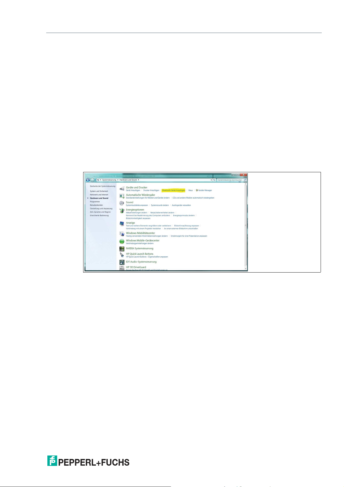
3.2 Pairing with PC
Select the Bluetooth® name of the RSM-Ex® 01 BT via Start -> Control Panel -> Hardware
and Sound -> Add a Bluetooth device. The PC is now paired with the RSM-Ex 01 BT and a
Bluetooth® connection can be established. This is indicated by the illuminating Bluetooth®
LED on the RSM-Ex® 01 BT.
Figure 3.1
2020-11
7
Page 8
RSM-Ex® 01 BT
Bluetooth®
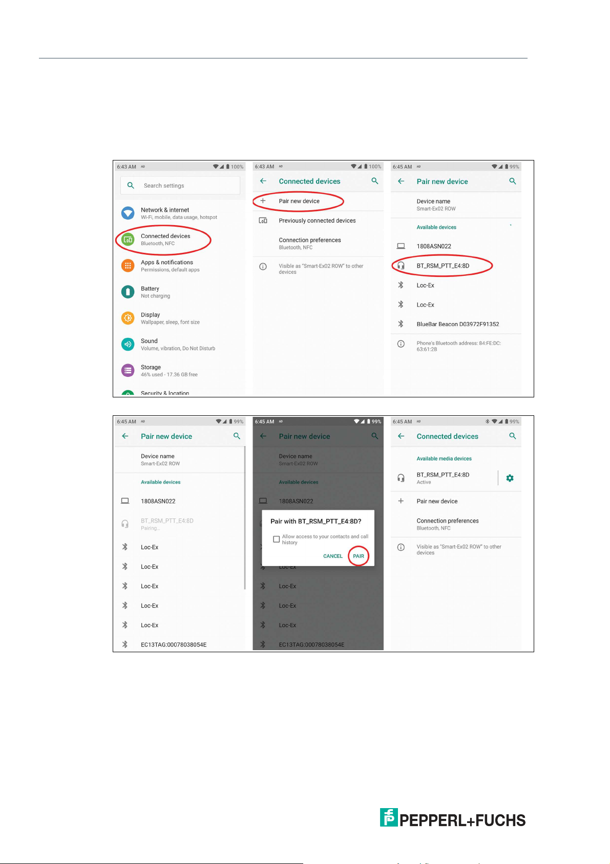
3.3 Pairing with Android® device
Pairing without "eSETUP RSM-Ex“ App:
"Settings“ -> "Connected devices“ -> “Pair new device” -> select BT_RSM_PTT -> RSM-Ex 01
BT and Smartphone/Tablet is paired
Figure 3.2
Figure 3.3
Pairing with the "eSETUP RSM-Ex“ App:
See 6.5 Bluetooth® connection.
3.4 Deleting a Connection
If you press Channel Up, Channel Down and MFB, an existing Bluetooth® connection can be
closed and the autoconnection is stopped.
8
2020-11
Page 9
RSM-Ex® 01 BT
Firmware Update
4 Firmware Update
4.1 Bootloader
New firmware can be installed for the RSM-Ex® 01 BT via the bootloader. New firmware can be
transferred to the RSM-Ex® 01 BT from a PC or mobile device (e.g. smartphone or tablet) via
Bluetooth®.
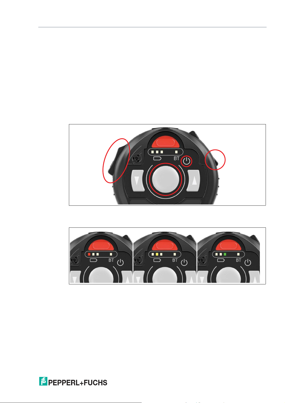
4.2 Launching the Bootloader on the RSM-Ex® 01 BT
To install new firmware on the RSM-Ex®01 BT, the RSM-Ex® 01 BT must be set to a certain
state, namely the bootloader. The bootloader can be launched by pressing and holding the Volume Down, PTT and MFB button when switching on the RSM-Ex® 01 BT. It must be ensured
that the RSM-Ex® 01 BT was previously switched off before launching the bootloader.
Figure 4.1
The bootloader starts to run on the RSM-Ex® 01 BT when the buttons are released (a light on
the battery display changes from red to yellow to green).
Figure 4.2
4.3 Installing New Firmware for the RSM-Ex® 01 BT (by Using a PC
Without "eSETUP RSM-Ex")
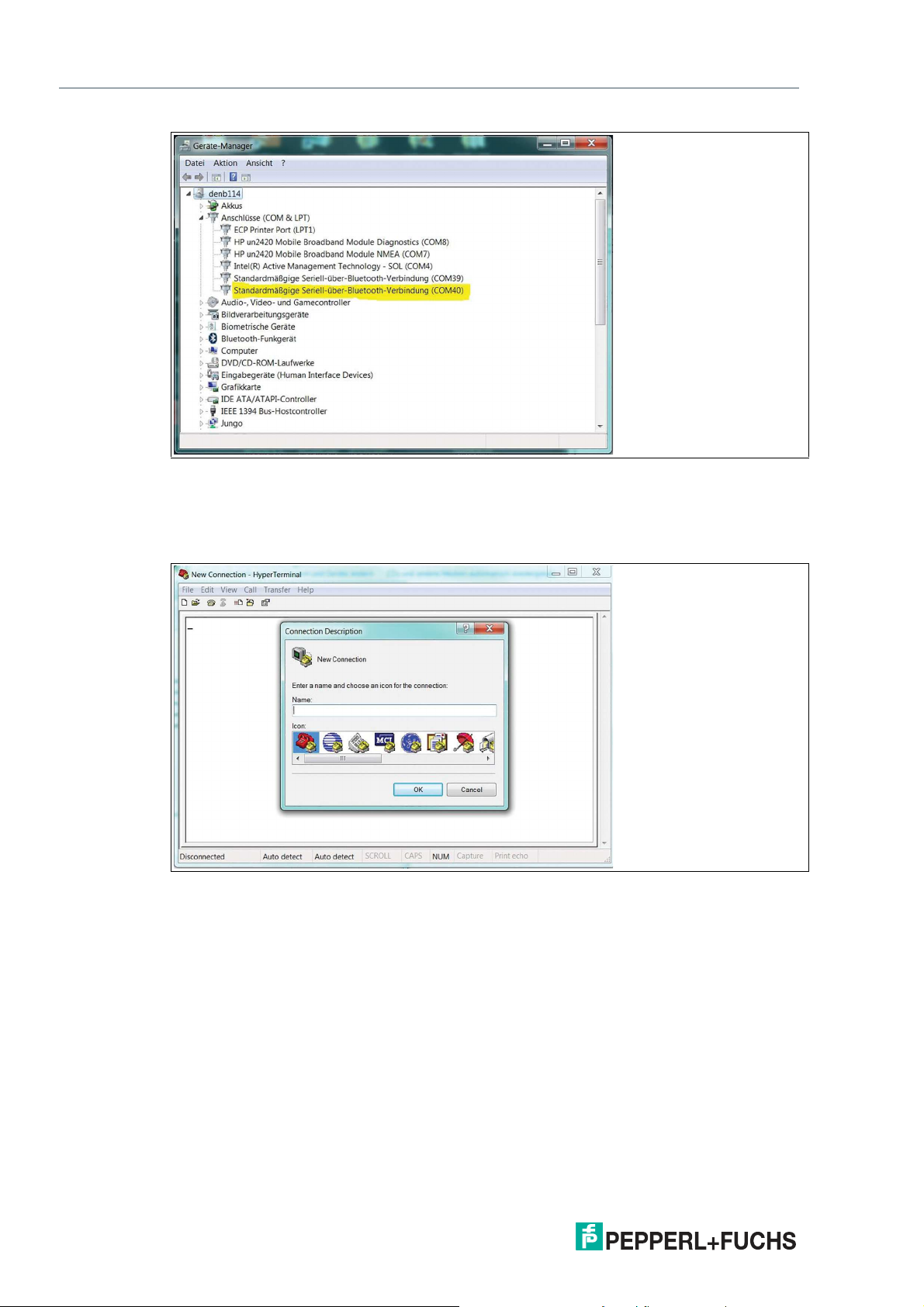
If the PC has been paired with the RSM-Ex® 01 BT, a Bluetooth® connection (SPP) can be
established via the HyperTerminal program. For this purpose, we must know which COM port
is being used for the Bluetooth® connection. This information can be viewed by selecting Start
-> Control Panel -> Hardware and Sound -> Device Manager and then the Ports (COM &
LPT) section.
2020-11
9
Page 10
RSM-Ex® 01 BT
Firmware Update
Figure 4.3
We can now use this information to establish a Bluetooth® connection with the RSM-Ex® 01
BT via the HyperTerminal program. Open the HyperTerminal program on your PC. Start by
assigning a name for the connection. This name can be freely selected (confirm by pressing
"OK").
10
Figure 4.4
In the next step, select the COM port that you want to use for the Bluetooth® connection (confirm by pressing "OK").
2020-11
Page 11
RSM-Ex® 01 BT
Firmware Update
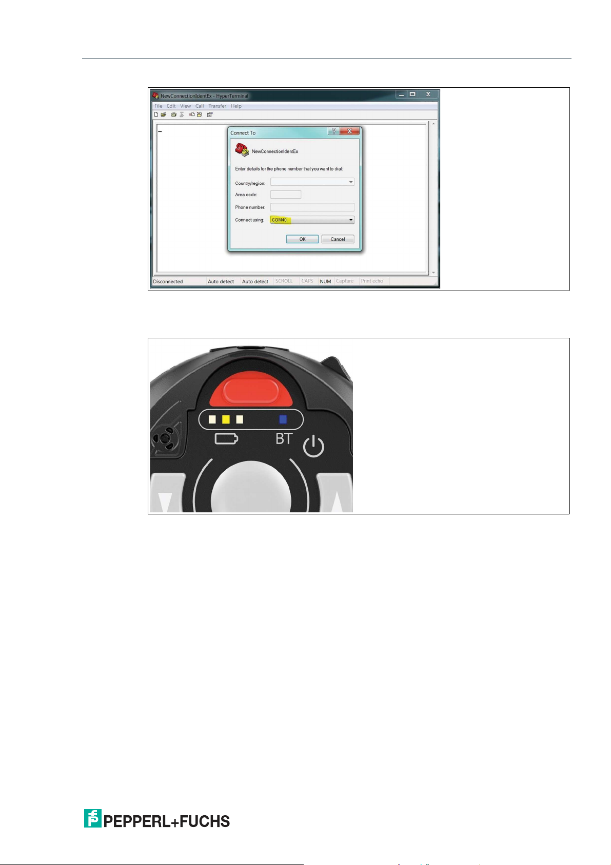
Figure 4.5
If everything was successful, Bluetooth® LEDs on the RSM-Ex® 01 BT illuminates. These
LEDs must illuminate, otherwise firmware cannot be installed on the RSM-Ex® 01 BT.
Figure 4.6
All necessary steps are now complete and new firmware can be installed on the RSM-Ex® 01
BT.
4.3.1 Installing New Firmware
The new firmware to be installed must be available as a file. A Bluetooth® connection must
have been established in the SPP mode before new firmware can be installed on the RSM-Ex®
01 BT (Bluetooth® LEDs must illuminate).
To install new firmware for the RSM-Ex® 01 BT, send the string "#IDSETTING" before firmware
data is sent in the HyperTerminal program. To do this, enter the string "#IDSETTING" in the
HyperTerminal program and press Enter by using the keyboard. The red LED on the RSM-Ex®
01 BT battery display starts flashing. This means the RSM-Ex® 01 BT is requesting data from
the PC.
2020-11
11
Page 12
RSM-Ex® 01 BT
Firmware Update
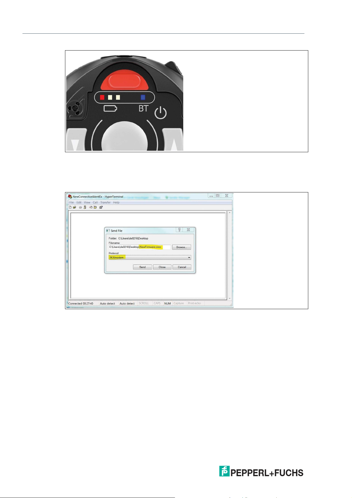
Figure 4.7
In the next step, we must send the file that contains the new firmware. To do this, we must
select the file in the HyperTerminal program window that opens when we select Transfer ->
Send File…. Select the file by clicking Browse... 1K XModem must be selected as the transfer protocol.
12
Figure 4.8
The file is sent by pressing Send. The transfer process starts.
2020-11
Page 13
RSM-Ex® 01 BT
Firmware Update
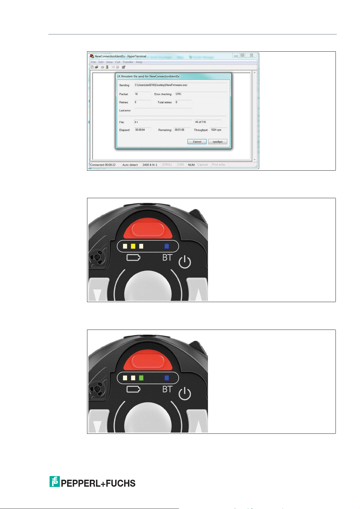
Figure 4.9
The yellow LED on the RSM-Ex® 01 BT battery display flashes when the transfer is in progress. The LED flashes until the transfer is complete or until an error occurs.
Figure 4.10
If the transfer was successful, the green LED on the RSM-Ex® 01 BT battery display illuminates briefly and then go out again.
Figure 4.11
The new firmware starts and we now exit the bootloader.
2020-11
13
Page 14

RSM-Ex® 01 BT
Firmware Update
If something went wrong during the data transfer process, the new firmware is not able to be
started and we remain in the bootloader (the light on the battery display changes from red to
yellow to green). If this occurs, the firmware has to be reinstalled and a new data transfer process must be started. If the Bluetooth® connection is lost when transferring firmware data
(Bluetooth® LED is off), a new Bluetooth® connection must be established before a new transfer process can be started.
4.4 Installing New Firmware on RSM-Ex® 01 BT (with PC and "eSETUP
RSM-Ex")
See 5.9 Installing New Firmware.
4.5 Installing New Firmware on RSM-Ex 01 BT (with Mobile Device)
See 6.9 Installing New Firmware.
14
2020-11
Page 15

RSM-Ex® 01 BT
"eSETUP RSM-Ex" Windows
5 "eSETUP RSM-Ex" Windows
5.1 Generic
An XML file is used to transfer data to the RSM-Ex® 01 BT. This file will be created by the
"eSETUP RSM-Ex" software and transferred to the RSM-Ex® 01 BT.
First start
After the first start of the software, an “BT_RSM01” folder will be created in the “document”
directory and several config files will be added to this folder. These XML files are default settings for the RSM-Ex® 01 BT.
5.2 Settings
The “SETTINGS” tab is used to read and write XML files, transfer data to the RSM-Ex® 01 BT
and manage the Bluetooth® connection.
5.3 Load File
5.3.1 Generic
The default settings will be loaded after the first start of the "eSETUP RSM-Ex" software. After
loading another file through the button “LOAD OTHER”, this file path will be stored and loaded
automatically at the next start. The last saved or opened file will be loaded at the next start.
5.3.2 Load Default Settings
Press the button “LOAD DEFAULT” to load the default settings of the RSM-Ex® 01 BT. This
setting file is stored in the installation folder “data/RSMEx01Config.xml”.
5.3.3 Load Other Settings
Press the button “LOAD OTHER” to load any settings XML file. After pressing the button, you
can select the file in the opened file dialog and after confirming with “OPEN” the file will be
loaded into the "eSETUP RSM-Ex" software. The status bar shows the successful loading of
the file.
Figure 5.1
If the reading of the file was interrupted, the syntax of the file was not complied.
It is possible to load one of the last 3 saved or loaded files. These files were stored in the dropdown list. To open one of these files, select one and press the button “LOAD”.
5.4 Save File
The settings can be saved with the button “SAVE” and “SAVE AS”. The status bar shows the
progress and faults.
Figure 5.2
2020-11
15
Page 16

RSM-Ex® 01 BT
"eSETUP RSM-Ex" Windows
5.5 Bluetooth® Connection
The “Connect to RSM-Ex 01 via SPP profile” part is managing the Bluetooth® connection to
the RSM-Ex® 01 BT. It is possible to use the integrated Bluetooth® module or a USB to Bluetooth® converter to connect your PC with your RSM-Ex® 01 BT.
5.5.1 Bluetooth® Connection of RSM-Ex® 01 BT and PC
If the PC is paired with the RSM-Ex® 01 BT, the connection will be available over COM-PORT
(Bluetooth® pairing see 3.1 Bluetooth® pairing). This COM-PORT can now be selected from
the drop-down list to connect in SPP profile.
Figure 5.3
If the required COM-Port is not shown in the drop-down list, refresh the list with the button “R”.
If the required COM-Port is still not available, check the “show all COM-PORTs” checkbox and
all available COM-PORTs are shown.
5.5.2 Connecting
After selecting the right COM-PORT for the Bluetooth® connection, press the button “CON-
NECT”. If everything was successful, the status bar shows “connected” and the visual indicator
switches from red to green.
Figure 5.4
Also the Bluetooth® LED on the RSM-Ex® 01 BT illuminates. These LEDs must illuminate, otherwise the connection was not made correctly.
16
2020-11
Page 17

RSM-Ex® 01 BT
"eSETUP RSM-Ex" Windows
Figure 5.5
5.6 Transfer Data to RSM-Ex® 01 BT
Before sending data to the RSM-Ex® 01 BT, the Bluetooth® connection must be compounded
(Bluetooth® LED illuminating). Now you can send the data to the RSM-Ex® 01 BT.
The "eSETUP RSM-Ex" software save all settings before sending the data to the RSM-Ex® 01
BT. Select a file at “Save data to XML file” where the settings are saved. After choosing the
right file, press the button “SAFE AND SEND”. The settings are saved in the chosen file and
send to the RSM-Ex® 01 BT. If the data transfer has started, a progress bar shows the progress
in the status bar.
Figure 5.6
The successful or terminated transfer of the data will be shown in the status bar.
2020-11
17
Page 18

RSM-Ex® 01 BT
"eSETUP RSM-Ex" Windows
Figure 5.7
If the data transfer was interrupted, check the Bluetooth® connection (Bluetooth® LED illuminating) and start a new download.
18
2020-11
Page 19

RSM-Ex® 01 BT
"eSETUP RSM-Ex" Windows
5.7 Read Data from RSM-Ex® 01 BT
To read all settings from the RSM-Ex® 01 BT, press the button “READ”. All settings saved in
the RSM-Ex® 01 BT are transmitted to the "eSETUP RSM-Ex" software.
Save all settings before reading data from the RSM-Ex® 01 BT, otherwise these settings are
overridden (“SAVE” or “SAVE AS” button).
After pressing the button “READ”, the RSM-Ex® 01 BT is sending all settings to the "eSETUP
RSM-Ex" software. The progress of the data transfer is shown in a progress bar in the status
bar.
Figure 5.8
The status bar shows the successful or failed transfer of the data. If the data were received successfully, the settings are shown in the associated tab.
2020-11
19
Page 20

RSM-Ex® 01 BT
"eSETUP RSM-Ex" Windows
Figure 5.9
5.8 Online Mode
With the online mode it is possible to send data directly after modification to the RSM-Ex® 01
BT. There are two capabilities to activate the online mode. For each of these capabilities the
RSM-Ex® 01 BT must be connected via Bluetooth® (Bluetooth® LED illuminating).
1. After successful transfer a file to the RSM-Ex® 01 BT (“SAFE AND SEND”)
2. After reading the data from the RSM-Ex® 01 BT (“READ”)
the online mode is activated.
The actual state of the online mode is shown in the status bar (green -> online, red -> offline).
Figure 5.10
After activating the online mode, every change made in the tab GENERAL or BUTTONS, will
be sent directly to the RSM-Ex® 01 BT.
The status bar shows the successful transfer of the data. If the data transfer was interrupted or
terminated, the last set value is set and the online mode is deactivated.
20
2020-11
Page 21

RSM-Ex® 01 BT
"eSETUP RSM-Ex" Windows
5.9 Installing New Firmware
All settings for the firmware update were made in the tab “FIRMWARE UPDATE”. First of all the
new firmware file must be selected by pressing the button “…”. An open file dialog pops up and
the requested file can be selected. The newest firmware version can be downloaded by pressing the button “DOWNLOAD”. The download of the new firmware starts automatically if the PC
is connected to the internet.
Figure 5.11
Only “bin” or “srec” files can be selected as firmware update files. Other files are not allowed.
The RSM-Ex® 01 BT must be in bootloader mode (see 4.2 Launching the Bootloader on
the RSM-Ex 01 BT) before updating the firmware. After choosing the right file and the RSMEx® 01 BT is in bootloader mode and connected, press the button “UPDATE” to send the file to
the RSM-Ex® 01 BT.
If the data transfer has started, a progress bar shows the progress in the status bar.
Figure 5.12
Figure 5.13
The yellow LED on the RSM-Ex® 01 BT battery display flashes when the transfer is in progress. The LED flashes until the transfer is complete or until an error occurs.
2020-11
21
Page 22

RSM-Ex® 01 BT
"eSETUP RSM-Ex" Windows
Figure 5.14
If the transfer was successful, the green LED on the RSM-Ex® 01 BT battery display illuminates shortly and then switch off again.
Figure 5.15
After the file was transferred, the status bar will show the status of the data transfer.
Figure 5.16
After successful firmware update, the "eSETUP RSM-Ex" software set the connection state to
“not connected”, because the RSM-Ex® 01 BT restarts and the Bluetooth® connection was
terminated.
If something goes wrong during the data transfer process, the new firmware will not be able to
be started on the RSM-Ex® 01 BT and we remain in the bootloader (the light on the RSM-Ex®
01 BT battery display changes from red to yellow to green). If this occurs, the firmware must be
reinstalled and a new data transfer process must be started. If the Bluetooth® connection is lost
when transferring firmware data (the Bluetooth® LEDs on the RSM-Ex® 01 BT is off), a new
Bluetooth® connection must be established between the RSM-Ex® 01 BT and the PC before a
new transfer process can be started.
2020-11
22
Page 23

RSM-Ex® 01 BT
"eSETUP RSM-Ex" Windows
5.10 Device Info
The “Device Info” tab shows some information’s of the connected RSM-Ex® 01 BT. To receive
information from the RSM-Ex® 01 BT, it must be connected via Bluetooth® (Bluetooth® LED
illuminating). These data is shown:
• Battery Level
Battery level of the RSM-Ex® 01 BT in %
• Firmware Version
Firmware version of the RSM-Ex® 01 BT
• Firmware Version Bootloader
Firmware version of the bootloaders
• Firmware Version Bluetooth-Module
Firmware version of the Bluetooth® module
• Bluetooth Address
Bluetooth® address of the RSM-Ex® 01 BT
• Paired Devices 1-5
Bluetooth® address of the last five connected devices
Figure 5.17
2020-11
23
Page 24

RSM-Ex® 01 BT
"eSETUP RSM-Ex" Windows
5.11 About
Information about manufacturer and download link to the newest "eSETUP RSM-Ex" software
version.
Figure 5.18
24
2020-11
Page 25

RSM-Ex® 01 BT
"eSETUP RSM-Ex" Android
6 "eSETUP RSM-Ex" Android
The "eSETUP RSM-Ex" App can be downloaded under https://www.ecom-ex.com/apps/ from
the ecom instruments GmbH homepage and in the Google Play Store.
6.1 Generic
An XML file is used to transfer data to the RSM-Ex® 01 BT. This file is created by the "eSETUP
RSM-Ex" software and transferred to the RSM-Ex® 01 BT.
First start
After the first start of the software, an “RSM-Ex01” folder will be created in the “device storage”
directory and several config files will be added to this folder. These XML files are default settings for the RSM-Ex® 01 BT.
6.2 Connection
The “CONNECTION” tab is used to read and write XML files, transfer data to the RSM-Ex® 01
BT and manage the Bluetooth® connection.
6.3 Load File
6.3.1 Generic
The default settings will be loaded after the first start of the "eSETUP RSM-Ex" software. After
loading another file through the button “LOAD OTHER”, this file path will be stored and loaded
automatically at the next start. The last saved or opened file will be loaded at the next start.
6.3.2 Load Default Settings
Press the button “LOAD DEFAULT” to load the default settings of the RSM-Ex® 01 BT.
2020-11
25
Page 26

RSM-Ex® 01 BT
"eSETUP RSM-Ex" Android
6.3.3 Load Other Settings
Press the button “LOAD OTHER” to load any settings XML file. After pressing the button, you
can select the file in the opened file dialog. After confirming with “open”, the file is loaded into
the "eSETUP RSM-Ex" app. A pop-up message shows the successful loading of the file.
26
Figure 6.1
If the reading of the file was interrupted, the syntax of the file was not complied.
It is possible to load one of the last three saved or loaded files. These files were stored in the
drop-down list. To open one of these files, select one and press the button “LOAD”.
2020-11
Page 27

RSM-Ex® 01 BT
"eSETUP RSM-Ex" Android
6.4 Save File
The settings can be saved with the button “SAVE” and “SAVE AS”. A pop-up message shows
the successful or faulty saving progress.
Figure 6.2
2020-11
27
Page 28

RSM-Ex® 01 BT
"eSETUP RSM-Ex" Android
6.5 Bluetooth® Connection
A Bluetooth® connection can be established under the "CONNECTION" tab by pressing "connect".
Figure 6.3
A window opens which contains one or more names of one or more Bluetooth® devices that
can be connected. The default Bluetooth® name of the RSM-Ex® 01 BT is "BT_RSM_PTT". If
a different Bluetooth® name has been set for RSM-Ex® 01 BT (see BT name), this name must
be selected.
2020-11
28
Page 29

RSM-Ex® 01 BT
"eSETUP RSM-Ex" Android
Figure 6.4
If the mobile device has not yet been paired with the RSM-Ex® 01 BT, a window will appear
after selecting the Bluetooth® name of the RSM-Ex® 01 BT to query whether a connection
should be established with the RSM-Ex® 01 BT. After confirming the query, a Bluetooth® connection is established between the RSM-Ex® 01 BT and the mobile device. If the corresponding Bluetooth® name of the RSM-Ex® 01 BT does not appear in the list of Bluetooth® devices,
you can perform a search for the RSM-Ex® 01 BT by selecting "Scan for devices".
If a Bluetooth® connection has been established successfully between the RSM-Ex® 01 BT
and the mobile device, the Bluetooth® LEDs on the RSM-Ex® 01 BT illuminates. These LEDs
must illuminate, otherwise firmware cannot be installed on the RSM-Ex® 01 BT.
Figure 6.5
2020-11
29
Page 30

RSM-Ex® 01 BT
"eSETUP RSM-Ex" Android
6.6 Transfer Data to RSM-Ex® 01 BT
Before sending data to the RSM-Ex® 01 BT, the Bluetooth® connection must be compounded
(Bluetooth® LED illuminating). Is the connection made, you can send the data to the RSM-Ex®
01 BT.
The "eSETUP RSM-Ex" app saves all settings before sending the data to the RSM-Ex® 01 BT.
Select a file under “Save data to XML file” where the settings will be saved. After choosing the
right file, press the button “SAFE AND SEND”. The settings are saved in the chosen file and
send to the RSM-Ex® 01 BT. If the data transfer has started, a progress bar shows the progress.
Figure 6.6
The successful or terminated transfer of the data will be shown in a pop-up message.
30
2020-11
Page 31

RSM-Ex® 01 BT
"eSETUP RSM-Ex" Android
Figure 6.7
If the data transfer was interrupted, check the Bluetooth® connection (Bluetooth® LED illuminating) and start a new download.
2020-11
31
Page 32

RSM-Ex® 01 BT
"eSETUP RSM-Ex" Android
6.7 Read data from RSM-Ex® 01 BT
To read all settings from the RSM-Ex® 01 BT, press the button “READ”. All settings saved in
the RSM-Ex® 01 BT will be transmitted to the "eSETUP RSM-Ex" software.
Save all settings before reading data from the RSM-Ex® 01 BT, otherwise these settings are
overridden (“SAVE” or “SAVE AS” button).
32
Figure 6.8
After pressing the button “READ”, the RSM-Ex® 01 BT is sending all settings to the "eSETUP
RSM-Ex" software. This opens a window which displays the progress of the transfer.
2020-11
Page 33

RSM-Ex® 01 BT
"eSETUP RSM-Ex" Android
Figure 6.9
A message is displayed on the mobile device to indicate the successful or failed transfer of the
data. If the data were received successfully, the settings will be shown in the associated tab.
Figure 6.10
2020-11
33
Page 34

RSM-Ex® 01 BT
"eSETUP RSM-Ex" Android
6.8 Online Mode
With the online mode it is possible to send data directly after modification to the RSM-Ex® 01
BT. There are two capabilities to activate the online mode. For each of these capabilities the
RSM-Ex® 01 BT must be connected via Bluetooth® (Bluetooth® LED illuminating).
1. After successful transfer a file to the RSM-Ex® 01 BT (“SAFE AND SEND”)
2. After reading the data from the RSM-Ex® 01 BT (“READ”)
the online mode is activated.
The actual state of the online mode is shown in the status bar (green -> online, red -> offline).
34
Figure 6.11
After activating the online mode, every change made in the tab GENERAL and BUTTONS is
sent directly to the RSM-Ex® 01 BT.
2020-11
Page 35

RSM-Ex® 01 BT
"eSETUP RSM-Ex" Android
The status bar shows the successful transfer of the data. If the data transfer was interrupted or
terminated, the last set value is set and the online mode is deactivated.
6.9 Installing New Firmware
Navigate to the "FIRMWARE UPDATE" tab and press "..." to select the file that contains the
new firmware for the RSM-Ex® 01 BT.
Press the “DOWNLOAD” Button to download the newest firmware from the ECOM Instruments
GmbH server.
Figure 6.12
Pressing "..." opens a window in which the file with the new firmware can be selected.
2020-11
35
Page 36

RSM-Ex® 01 BT
"eSETUP RSM-Ex" Android
Figure 6.13
After selecting the corresponding file that contains the new firmware, we are transferred back to
the software update menu. The RSM-Ex® 01 BT must be in bootloader mode (see 4.2
Launching the Bootloader on the RSM-Ex® 01 BT) and connected with SPP profile before
updating the firmware.
The new firmware for the RSM-Ex® 01 BT can now be installed by pressing "UPDATE".
36
2020-11
Page 37

RSM-Ex® 01 BT
"eSETUP RSM-Ex" Android
Figure 6.14
This opens a window which displays the progress of the transfer.
Figure 6.15
The yellow LED on the RSM-Ex® 01 BT battery display flashes when the firmware data is being
transferred. The LED flashes until the transfer is complete or until an error occurs.
2020-11
37
Page 38

RSM-Ex® 01 BT
"eSETUP RSM-Ex" Android
Figure 6.16
If the transfer was successful, the green LED on the RSM-Ex® 01 BT battery display illuminates shortly.
Figure 6.17
A message is displayed on the mobile device to indicate that the transfer was successful.
2020-11
38
Page 39

RSM-Ex® 01 BT
"eSETUP RSM-Ex" Android
Figure 6.18
The new firmware is launched on the RSM-Ex® 01 BT and the bootloader is closed.
If something went wrong during the data transfer process, the new firmware is not able to be
started on the RSM-Ex® 01 BT and we remain in the bootloader (the light on the RSM-Ex® 01
BT battery display changes from red to yellow to green). If this occurs, the firmware has to be
reinstalled and a new data transfer process must be started. If the Bluetooth® connection is lost
when transferring firmware data (the Bluetooth® LEDs on the RSM-Ex 01 BT is off), a new
Bluetooth® connection must be established between the RSM-Ex® 01 BT and the mobile
device before a new transfer process can be started.
2020-11
39
Page 40

RSM-Ex® 01 BT
"eSETUP RSM-Ex" Android
6.10 Device Info
The “Device Info” tab shows some information’s of the connected RSM-Ex® 01 BT. To receive
information from the RSM-Ex® 01 BT, it must be connected via Bluetooth® (Bluetooth® LED
illuminating). These data is shown:
• Battery Level
Battery level of the RSM-Ex® 01 BT in %
• Firmware Version
Firmware version of the RSM-Ex® 01 BT
• Firmware Version Bootloader
Firmware version of the bootloaders
• Firmware Version Bluetooth-Module
Firmware version of the Bluetooth® module
• Bluetooth Address
Bluetooth® address of the RSM-Ex® 01 BT
• Paired devices 1-5
Bluetooth® address of the last 5 connected devices
40
Figure 6.19
2020-11
Page 41

RSM-Ex® 01 BT
"eSETUP RSM-Ex" Android
6.11 About
Information about manufacturer and download link to the newest "eSETUP RSM-Ex" app.
Figure 6.20
2020-11
41
Page 42

RSM-Ex® 01 BT
Annex A
7 Annex A
7.1 General RSM-Ex® 01 BT Settings
Settings Options Default value Description
General
Switch off time (in
minutes)
BT
BT name 0-140 characters BT_RSM_PTT Setting for the Blue-
Add BT ID to name 0
Autoconnect 0
Enable CVC 0 -> disabled
Enable Wide-BandSpeech
Enable Inband Ring 0 -> disabled
Enable NREC 0 -> disabled
Audio
0-10 5 Specification of a time
1
2
3
4
5
6
1
1 -> enabled
0 -> disabled
1 -> enabled
1 -> enabled
1 -> enabled
after which the RSMEx 01 BT switches off
automatically if a Bluetooth® connection is
not available and the
RSM-Ex 01 BT is not
located in the docking
station/being charged.
Specification in minutes. Interval in 1-minute increments.
tooth® name of the
RSM-Ex 01 BT.
2 How many words of
the Bluetooth® ID
should be written at
the end of the BT
Name. e.g. Value = 2
ID =
00:11:22:33:44:55 BT
Name = BTRSM_PTT_44:55
1 Setting if the RSM-Ex
01 BT should automatically connect to
the last connected
device after start.
1 Enable / disable clear
Voice capture
1 Enable / disable Wide
Band Speech
1 Enable / disable in-
band ringing for
incoming calls
0 Set / unset NREC flag
to tell AG to no
use/use internal Noise
Reduction/Echo Canceler algorithm 0 ->
AG should use internal Noise Reduction/Echo Canceler
algorithm. 1 -> AG
should not use internal
Noise Reduction/Echo
Canceler algorithm.
42
2020-11
Page 43

RSM-Ex® 01 BT
Annex A
Settings Options Default value Description
Voice Prompt Function 0 -> Off
Side Tone Volume 0-15 4 Volume setting of the
Accelerometer
Accelerometer function
Preamble 0-32 characters Specification of char-
Postamble 0-32 characters Specification of char-
Delimiter 0-4 characters Specification of the
SOS Button
Button function 0 -> Disabled
Pressed AT Command
Released AT Command
Pressed SPP Command
Released SPP Command
PTT Button
Button function 0 -> Disabled
Pressed AT Command
1 -> On
0 -> Off
1 -> On
1 -> AT Command
2 -> SPP Command
3 -> Default
0-32 characters Specification which AT
0-32 characters Specification which AT
0-32 characters SOS=P Specification which
0-32 characters SOS=R Specification which
1 -> AT Command
2 -> SPP Command
3 -> Default
0-32 characters Specification which AT
1 Setting if Voice-
Prompts should be
enabled or not.
side tone volume.
1 Setting if the acceler-
ometer should be
enabled or not.
acters that are
appended to the front
of data from the accelerometer.
acters that are
appended to the end
of data from the accelerometer.
delimiter between the
X, Y and Z value of the
accelerometer.
2 Specification which
function the button
has.
command should be
sent when the button
is pressed.
command should be
sent when the button
is released.
SPP command should
be sent when the button is pressed.
SPP command should
be sent when the button is released.
2 Specification which
function the button will
have.
command should be
sent when the button
is pressed.
2020-11
43
Page 44

RSM-Ex® 01 BT
Annex A
Settings Options Default value Description
Released AT Command
Pressed SPP Command
Released SPP Command
MFB Button
Button function 0 -> Disabled
Pressed AT Command
Released AT Command
Pressed SPP Command
Released SPP Command
Channel Up Button
Button function 0 -> Disabled
Pressed AT Command
Released AT Command
Pressed SPP Command
Released SPP Command
Channel Down Button
0-32 characters Specification which AT
0-32 characters +PTT=P Specification which
0-32 characters +PTT=R Specification which
3 Specification which
1 -> AT Command
2 -> SPP Command
3 -> Default
0-32 characters Specification which AT
0-32 characters Specification which AT
0-32 characters Specification which
0-32 characters Specification which
2 Specification which
1 -> AT Command
2 -> SPP Command
3 -> Default
0-32 characters Specification which AT
0-32 characters CH_UP=P Specification which AT
0-32 characters CH_UP=R Specification which
0-32 characters Specification which
command should be
sent when the button
is released.
SPP command should
be sent when the button is pressed.
SPP command should
be sent when the button is released.
function the button
has.
command should be
sent when the button
is pressed.
command should be
sent when the button
is released.
SPP command should
be sent when the button is pressed.
SPP command should
be sent when the button is released.
function the button
has.
command should be
sent when the button
is pressed.
command should be
sent when the button
is released.
SPP command should
be sent when the button is pressed.
SPP command should
be sent when the button is released.
44
2020-11
Page 45

RSM-Ex® 01 BT
Annex A
Settings Options Default value Description
Button function 0 -> Disabled
Pressed AT Command
Released AT Command
Pressed SPP Command
Released SPP Command
Volume Up Button
Button function 0 -> Disabled
Pressed AT Command
Released AT Command
Pressed SPP Command
Released SPP Command
Volume Down Button
Button function 0 -> Disabled
Pressed AT Command
Released AT Command
1 -> AT Command
2 -> SPP Command
3 -> Default
0-32 characters Specification which AT
0-32 characters CH_DOWN=P Specification which AT
0-32 characters CH_DOWN=R Specification which
0-32 characters Specification which
1 -> AT Command
2 -> SPP Command
3 -> Default
0-32 characters Specification which AT
0-32 characters Specification which AT
0-32 characters Specification which
0-32 characters Specification which
1 -> AT Command
2 -> SPP Command
3 -> Default
0-32 characters Specification which AT
0-32 characters Specification which AT
2 Specification which
function the button
has.
command should be
sent when the button
is pressed.
command should be
sent when the button
is released.
SPP command should
be sent when the button is pressed.
SPP command should
be sent when the button is released.
3 Specification which
function the button
has.
command should be
sent when the button
is pressed.
command should be
sent when the button
is released.
SPP command should
be sent when the button is pressed.
SPP command should
be sent when the button is released.
Specification which
function the button
has.
command should be
sent when the button
is pressed.
command should be
sent when the button
is released.
2020-11
45
Page 46

RSM-Ex® 01 BT
Annex A
Settings Options Default value Description
Pressed SPP Command
Released SPP Command
0-32 characters Specification which
SPP command should
be sent when the button is pressed.
0-32 characters Specification which
SPP command should
be sent when the button is released.
46
2020-11
Page 47

Pepperl+Fuchs Qua lit y
Download our latest poli cy he re:
www.pepperl-fuchs.com/quali ty
© Pepperl+Fuchs · Subject to modifications
www.pepperl-fuchs.com
Printed in Germany / DOCT-7035
 Loading...