

Pepperl+Fuchs RMS-G-RC, RMS-G-RC-NA Brief Instructions
RMS-G-RC · RMS-G-RC-NA English
General Information for Your Safety
This device must be installed and maintained only by qualified, trained personnel.
Observe the safety requirements of EN 60950-1. Operate the sensor only with an SELV supply with a limited
output of up to 100 W. Use a T2.5 A fuse, for example, to reliably limit the power output.
Brief Instructions: Radar Motion Sensor for Detecting Objects at Automatic Gates
Scope of delivery
Quantity Designation
1 RMS-G-RC
1 Connection cable with plug
1 Self-adhesive drilling template
2 Screws for mounting
1 Mounting instructions
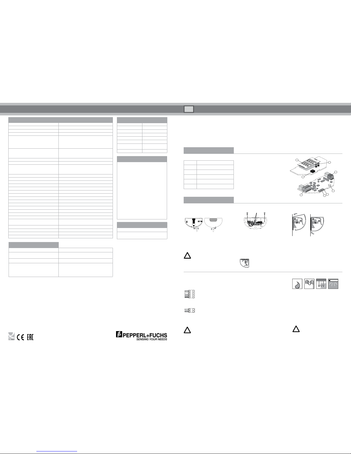
Operating elements
Antenna
IR receiver
IR transmitter
Terminal (power supply/main relay)
Terminal (vehicle relay)
Programming button / menu
Programming button / value
LED (red/green)
2
1
3
4
5
7
6
8
Product Information
Connecting the radar
Connect the cable to the terminal as follows:
Power supply/main relay
4
3
2
1
AC/DC supply (brown)
AC/DC supply (green)
Main relay (white)
Main relay (yellow)
Vehicle-presence relay
2
1
Vehicle relay (gray)
Vehicle relay (pink)
Opening the device
1. Insert the screwdriver into the opening
provided and carefully push open the cover.
2. Fold up the cover and remove it toward the
front.
Do not open the housing from the top.
Mounting the device
1. Attach the self-adhesive template and
drill according to the markings on the
template.
2. Pull the cable through the opening
provided.
3. Fasten the base plate using the screws
(screws are in the housing).
Installation
Installation information
• Protect the radar from rain*.
• Avoid placing moving objects in
the detection area (fans, plants,
trees, flags).
• Do not cover the radar.
Mechanically operated drive
components may affect the radar.
• Avoid fluorescent lights in the detection field.
Closing the device
click
Attach the cover on the top
and press down until it snaps into place.
!
!
World Headquarters
Pepperl+Fuchs GmbH, Lilienthalstrasse 200
68307 Mannheim, Germany
Email: FA-info@de.pepperl-fuchs.com
USA Headquarters
Pepperl+Fuchs Inc. Twinsburg. USA
Email: FA-info@us.pepperl-fuchs.com
Asia Pacific Headquarters
Pepperl+Fuchs Pte Ltd. Singapore 139942
Email: FA-info@sg.pepperl-fuchs.com
www.pepperl-fuchs.com
Technical Data
Functional principle Microwave module
Detection speed Min. 0.1 m/s
Marking CE
Inclination angle 0 – 40° in 5° steps
Detection range 6000 x 7000 mm (WxD) at installation height of
5000 mm and inclination angle of 30°
5000 x 8000 mm (WxD) at installation height of
7000 mm and inclination angle of 30°
Operating frequency 24.15 GHz – 24.25 GHz K band
FCC (NA version): 24.075 GHz – 24.175 GHz K
band
Operating mode Radar motion sensor
Function indicator Red/green LED
Operating elements Two pushbuttons for programming of direction
detection, vehicle detection, switching mode, size
of detection area, adjuster for fall time
Operating voltage 12 – 36 VDC/12 – 28 VAC
No-load current < 50 mA at 24 VDC
Power consumption < 1 W
Switching mode Active/passive
Signal output 2 relay outputs, NO/NC
Switching voltage Max. 48 VAC / 48 VDC
Nominal power Max. 0.5 AAC/1 ADC
Max. switching current 1 A
Switching power Max. 24 W/60 VA
Fall time 0.2 s – 5 s, adjustable
Ambient temperature -20° C to +60° C/253 – 333 K
Relative humidity Max. 90 %, not condensing
Mounting height Max. 7000 mm
Degree of protection IP 54
Connection 4-pin plug-in screw terminals,
8 m connection cable, 2-pin and 4-pin
Housing material Polycarbonate (PC), ABS
Mass 120 g
Transmitting power (EIRP) < 20 dBm
Dimensions excluding securing parts 123 mm (w) x 65 mm (h) x 57 mm (d)
Troubleshooting
Fault Corrective action
Gate is detected.
Decrease the size of the detection area.
Change the inclination angle.
LED not lit up.
No power supply, device not functioning.
Remote control does not respond Device is locked. Switch the operating voltage off
and on again. The sensor can now be configured
without a code for 30 minutes.
Check the remote control battery.
Factory Settings
Function Setting
Detection area size Remote control: 8
Inclination angle 15°
Direction detection Forward
Fall time 1 s
Relay contact NO contact, active
Cross-traffic
suppression
Remote control:
Medium
Vehicle detection Medium
Accessories
RMS remote control
Remote control
RMS Weather Cap
Mounting set and
weather protective
Conformity with Standards
EU conformity: Pepperl+Fuchs GmbH hereby
declares that the radio system type RMS-GRC complies with Directive 2014/53/EU.
The full declaration of conformity is available at
www.pepperl-fuchs.com.
US conformity: The product RAVE-D-NA is
compliant with Part 15 of the FCC regulations.
IMPORTANT! The EU-compliant devices must
not be marketed in the United States and the
US-compliant devices must not be marketed in
Europe!
DOCT-1603H
Pepperl+Fuchs GmbH is certified according to ISO 9001. Item no. 215077 02/2018
For RMS-G-RC
Can be mounted on the ceiling using the RMS
Weather Cap
(see accessories)
Commissioning
Before switching on the device, remove all
objects from the gate area that do not normally belong there.
After applying the operating voltage, the
hardware and software are initialized.
This process takes approx. 10 seconds.
The LED flashes red/green.
Once this process is complete, configure the
radar. Check the settings by walking within
range of the radar.
To meet UL508 requirements, a 2.5 A slow-blow fuse should be used
between the device and the power supply.
!
* Installation of the RMS Weather
Cap is recommended
(see accessories).
RMS-G-RC · RMS-G-RC-NA
Programming Mode
Programming example: changing the relay fall time from 1.0 s to 3.0 s
Function/setting Action LED
MENU
2 s
Press and hold the MENU button for
two seconds.
Programming starts
LED
flashes
The current value is read out, e.g.:
1x red for function: sensitivity
8x green for value: 8
R
G
1x 8x
MENU
3x
Set the function:
Press the MENU button three times.
LED
flashes
4x red for function: fall time for output
3x green for value: 1.0 s
R
G
4x 3x
VALUE
3x
Set the value:
Press the VALUE button three times.
LED
flashes
4x red for function: fall time for output
6x green for value: 3.0 s
R
G
4x 6x
MENU
2 s
Press and hold the MENU button for
two seconds.
Programming is ended.
The settings are saved.
Program the sensor using the MENU and VALUE buttons. When one of these buttons is pressed, the flash code is interrupted. The set value is output in
accordance with the table below. Once the final table entry (7) has been reached, the next press of a button calls up the first table entry (1) again.
Each time a button is pressed, the setting is automatically stored.
Programming mode is exited automatically if no setting is made within ten minutes. The set values are stored.
Starting programming
MENU
2 s
Press and hold the MENU button for approximately two
seconds.
Programming mode is activated.
R
G
The LED indicates the settings by flashing:
- Red flashing indicates the function
- Green flashing indicates the setting (value)
- No flashing indicates that the function is switched off
Setting the function and value
MENU
1x
Press the MENU button once.
The next function is selected.
VALUE
1x
Press the VALUE button once.
The value is increased by 1.
Stopping programming
MENU
2 s
Press and hold the MENU button for approximately two
seconds.
Programming mode is exited.
The settings are stored.
Function
MENU
R
Setting VALUE
G
Description
Detection area size 1x 1 – 16 1 – 16x 01: Small detection area
16: Large detection area
Detection mode 2x
Off
Forward
Backward
0x
1x
2x
3x
No detection
Direction detection: Detects movements toward the radar
Direction detection: Detects movements away from the radar
No direction detection: Detects forward and backward movements
Vehicle detection 3x Off
Low
Medium
High
0x
1x
2x
3x
No detection; the vehicle relay is not activated
Low vehicle detection
Medium vehicle detection
High vehicle detection
Fall time for output 4x Off
0.2 s
0.5 s
1.0 s
1.5 s
2.0 s
3.0 s
4.0 s
5.0 s
0x
1x
2x
3x
4x
5x
6x
7x
8x
Off: Relay is not activated
0.2 s: Shortest fall time
10.0 s: Longest fall time
Relay contact 5x Closing active
Opening passive
1x2xRelay contact closes on detection (N. O.)
Relay contact opens on detection (N. C.)
Cross-traffic
suppression
6x Off
Low
Medium
High
0x
1x
2x
3x
No cross-traffic suppression
Low cross-traffic suppression
Medium cross-traffic suppression
High cross-traffic suppression
Device addresses 7x 1 – 16 1 – 16x Device addresses for programming with remote control.
Reset 2 s
MENU
2 s
VALUE
Press the VALUE and MENU
buttons together for approx. two
seconds.
Reset to factory settings
The LED flashes green/red alternately for approx. ten seconds
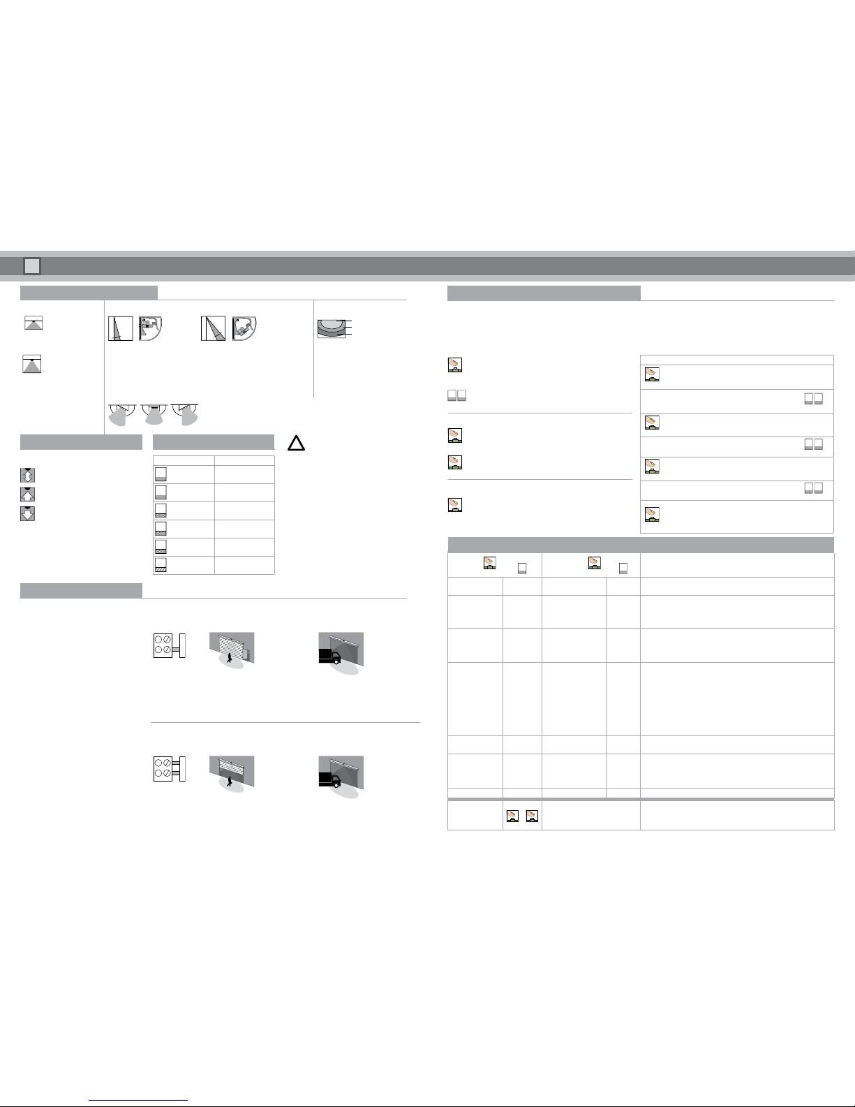
Vehicle Detection
The sensor evaluates movements of
people or vehicles in different ways and switches the relay.
Relay function
The sensor always switches the main relay
when people are detected and when vehicles
are detected.
The sensor only activates the vehicle relay
if vehicle detection is activated, a vehicle
is detected, and there are no people in the
detection area.
Application example: Gate with separate entrance for pedestrians
Gate control with one switching input. Vehicle detection is switched on.
Only the vehicle relay is connected.
1
2
Main relay
Vehicle relay
Person approaches:
- Vehicle relay is not activated
- Gate remains closed
- Person uses side entrance
Vehicle approaches:
- Vehicle relay is activated
- The LED flashes red/green in quick
succession
- The gate opens
Application example: Gate with no separate entrance for pedestrians
Gate control with two switching inputs. Vehicle detection switched on.
Main relay and vehicle relay are connected.
1
2
Detection Field Settings
Antenna characteristics Inclination angle Detection area size
Installation height:
5.00 m
Width: 6.00 m
Depth: 7.00 m
0° 40°
Min.
50 %
Max.
Installation height,
7.00 m
Width: 5.00 m
Depth: 8.00 m
You can change the position in 5° steps. To do so, hold the PCB at the side,
turn toward the front and move to the required position. The factory setting is 15°.
Inclined detection area
The PCB can also be inserted at an angle, up to 3 notches to the right or left.
Notches can also be removed.
Use the programming buttons or
remote control to set the sensitivity
and change the size of the detection
area.
Angle of inclination 30°
Size of detection area Max.
Some installation situations may limit the
adjustment options and the functions of the
sensor.
!
Detection Capabilities
Direction detection
No direction detection
With direction detection
forward (toward the radar)
With direction detection
backward (away from the radar)
Color indicator Status
G
Green
Device ready for
operation
R
Red Detection active
G
Green flashing Command received
R
Red flashing Fault
R/G
Red/green
flashing in quick
Vehicle relay is activated
R/G
Red/green
flashing slowly
Initialization
after switching on
LED Status Indicator
Check the settings of the programming buttons by walking within range of the sensor
 Loading...