

Page 1

HANDBUCH / MANUAL / MANUAL / MANUALE
HANDBUCH / MANUAL / MANUAL / MANUALE
Radar-Bewegungsmelder
Radar Motion Sensor
Avisador de movimientos radar
Rilevatori di movimento radar
RMS-FRW
FACTORY AUTOMATION
Page 2

Radar Motion Sensor RMS-FRW
1 Introduction . . . . . . . . . . . . . . . . . . . . . . . . . . . . . . . . . . . . . . . . . . . . . . . . . . . . . . . . . . . . . . . . . . . . . . . .32
1.1 Warranty . . . . . . . . . . . . . . . . . . . . . . . . . . . . . . . . . . . . . . . . . . . . . . . . . . . . . . . . . . . . . . . . . . . . . . . . . . . . . . . .32
2 Declaration of conformity . . . . . . . . . . . . . . . . . . . . . . . . . . . . . . . . . . . . . . . . . . . . . . . . . . . . . . . . . . . . .34
3 Safety . . . . . . . . . . . . . . . . . . . . . . . . . . . . . . . . . . . . . . . . . . . . . . . . . . . . . . . . . . . . . . . . . . . . . . . . . . . .35
3.1 Symbols used . . . . . . . . . . . . . . . . . . . . . . . . . . . . . . . . . . . . . . . . . . . . . . . . . . . . . . . . . . . . . . . . . . . . . . . . . . . .35
3.2 General safety instructions . . . . . . . . . . . . . . . . . . . . . . . . . . . . . . . . . . . . . . . . . . . . . . . . . . . . . . . . . . . . . . . . . .36
3.3 Standard-relevant safety settings . . . . . . . . . . . . . . . . . . . . . . . . . . . . . . . . . . . . . . . . . . . . . . . . . . . . . . . . . . . . .37
4 Product description . . . . . . . . . . . . . . . . . . . . . . . . . . . . . . . . . . . . . . . . . . . . . . . . . . . . . . . . . . . . . . . . . .38
4.1 Displays and operating elements . . . . . . . . . . . . . . . . . . . . . . . . . . . . . . . . . . . . . . . . . . . . . . . . . . . . . . . . . . . . .38
4.2 Scope of delivery . . . . . . . . . . . . . . . . . . . . . . . . . . . . . . . . . . . . . . . . . . . . . . . . . . . . . . . . . . . . . . . . . . . . . . . . .39
4.3 Accessories . . . . . . . . . . . . . . . . . . . . . . . . . . . . . . . . . . . . . . . . . . . . . . . . . . . . . . . . . . . . . . . . . . . . . . . . . . . . .40
5 Installation . . . . . . . . . . . . . . . . . . . . . . . . . . . . . . . . . . . . . . . . . . . . . . . . . . . . . . . . . . . . . . . . . . . . . . . .40
5.1 Storage and transportation . . . . . . . . . . . . . . . . . . . . . . . . . . . . . . . . . . . . . . . . . . . . . . . . . . . . . . . . . . . . . . . . . .40
5.2 Unpacking the device . . . . . . . . . . . . . . . . . . . . . . . . . . . . . . . . . . . . . . . . . . . . . . . . . . . . . . . . . . . . . . . . . . . . . .40
5.3 Mounting and connecting the device . . . . . . . . . . . . . . . . . . . . . . . . . . . . . . . . . . . . . . . . . . . . . . . . . . . . . . . . . .41
6 Commissioning . . . . . . . . . . . . . . . . . . . . . . . . . . . . . . . . . . . . . . . . . . . . . . . . . . . . . . . . . . . . . . . . . . . . .43
7 Operation . . . . . . . . . . . . . . . . . . . . . . . . . . . . . . . . . . . . . . . . . . . . . . . . . . . . . . . . . . . . . . . . . . . . . . . . .43
7.1 Keypad menu operation . . . . . . . . . . . . . . . . . . . . . . . . . . . . . . . . . . . . . . . . . . . . . . . . . . . . . . . . . . . . . . . . . . . .43
7.2 Remote control operation . . . . . . . . . . . . . . . . . . . . . . . . . . . . . . . . . . . . . . . . . . . . . . . . . . . . . . . . . . . . . . . . . . .46
8 Maintenance and repair . . . . . . . . . . . . . . . . . . . . . . . . . . . . . . . . . . . . . . . . . . . . . . . . . . . . . . . . . . . . . .49
9 Troubleshooting . . . . . . . . . . . . . . . . . . . . . . . . . . . . . . . . . . . . . . . . . . . . . . . . . . . . . . . . . . . . . . . . . . . .49
10 Appendix . . . . . . . . . . . . . . . . . . . . . . . . . . . . . . . . . . . . . . . . . . . . . . . . . . . . . . . . . . . . . . . . . . . . . . . . . .50
10.1 Explanation of sensor parameters . . . . . . . . . . . . . . . . . . . . . . . . . . . . . . . . . . . . . . . . . . . . . . . . . . . . . . . . . . . .50
10.2 Overview of sensor parameters . . . . . . . . . . . . . . . . . . . . . . . . . . . . . . . . . . . . . . . . . . . . . . . . . . . . . . . . . . . . . .54
10.3 Overview of remote control menu structure . . . . . . . . . . . . . . . . . . . . . . . . . . . . . . . . . . . . . . . . . . . . . . . . . . . . .55
10.4 Technical Data . . . . . . . . . . . . . . . . . . . . . . . . . . . . . . . . . . . . . . . . . . . . . . . . . . . . . . . . . . . . . . . . . . . . . . . . . . .56
10.5 Note . . . . . . . . . . . . . . . . . . . . . . . . . . . . . . . . . . . . . . . . . . . . . . . . . . . . . . . . . . . . . . . . . . . . . . . . . . . . . . . . . . .58
31
Page 3
Radar Motion Sensor RMS-FRW
Introduction
1 Introduction
Congratulations
You have chosen a device manufactured by Pepperl+Fuchs. Pepperl+Fuchs develops, produces and distributes
electronic sensors and interface modules for the automation technology market on a worldwide scale.
Contact
If you have any questions about the device, accessories or further functions, contact:
Pepperl+Fuchs GmbH
Lilienthalstraße 200
68307 Mannheim
Telefon: 0621 776-1111
Telefax: 0621 776-271111
E-Mail: fa-info@de.pepperl-fuchs.com
1.1 Warranty
Pepperl+Fuchs manufactures its hardware products in accordance with industry-standard practices. Pepperl+Fuchs
warrants its products will be free from defects in materials and workmanship, provided that the products are used
under normal operating conditions intended by the manufacturer. This warranty is provided to the original owner only
and is not transferable to any third party. This warranty is subject to any and all accompanying disclaimers, limitations
and other terms of this section.
Exclusion of liability
The warranty shall not apply to products that:
• have been repaired, modified or manipulated, unless carried out or expressly authorized by Pepperl+Fuchs,
• have not been maintained in accordance with the operating and handling instructions supplied by Pepperl+Fuchs,
• have been exposed to abnormal physical or electrical loads, immersed in liquids, or have been subject to one of
the following:
•breaking,
• crushing,
• incorrect use,
32
Page 4

Radar Motion Sensor RMS-FRW
Introduction
• abuse,
• power shortage,
• unsuitable voltage supply,
• incorrect polarity,
• negligence or accident
• have been used for a purpose other than that described in the operating and handling instructions.
Preventive maintenance is the responsibility of the customer and is not covered under this warranty.
General
With the exception of the above-mentioned warranties, Pepperl+Fuchs shall not accept warranties of any kind for
products supplied hereunder, neither of an explicit nor implicit nature, including, but not restricted to, implicit warranties for defects and warranties of suitability for a special purpose and non-infringement of third-party rights. The
above-named explicit warranties replace all obligations and liabilities on the part of Pepperl+Fuchs with regard to
damage, including, but not limited to, special, indirect or consequential damage in conjunction with the use or design
of the product. The liability of the seller to the buyer and other persons (irrespective of the reason for liability, whether
contract, warranty, impermissible activity, abuse and/or other causes) in conjunction with the use of a product shall,
under no circumstances, exceed the original purchase price of the product. Under no circumstances shall Pepperl+Fuchs be liable for consequential damage, special and indirect damage, collateral damage or fines or lost profits, turnover or data loss, even if Pepperl+Fuchs has been informed of this possibility in writing.
33
Page 5
Radar Motion Sensor RMS-FRW
0682
ISO9001
Declaration of conformity
2 Declaration of conformity
EC conformity:
are compliant with Directive 1999/5/EC, device class 2 and the following harmonized standards
EN 62311, EN 60950-1, EN 301 489-1, EN 301489-3, EN 300 440-2.
The products
RMS-FRW
Caution:
This device can be used in all countries within the European Union with the exception of Great Britain and France.
In other countries, all applicable national regulations must be observed.
Pepperl+Fuchs GmbH, in D-68301 Mannheim, has a certified quality assurance system in accordance with ISO
9001.
34
A complete version of the declaration of conformity is available for download at
www.pepperl-fuchs.com
.
Page 6
Radar Motion Sensor RMS-FRW
Safety
3Safety
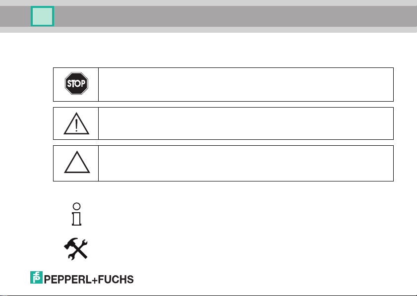
3.1 Symbols used
Safety-relevant symbols
Danger!
This symbol indicates an imminent danger.
Failure to avoid this danger can lead to serious injury or death.
Warning!
This symbol indicates a possible fault or danger.
Failure to avoid this warning can lead to serious injury or serious property damage.
Caution!
This symbol warns of a possible fault.
Failure to observe the instructions given in this caution may result in the devices and any
connected facilities or systems developing a fault or failing completely.
Informative symbols
Note!
This symbol draws your attention to important information.
Instruction
This symbol indicates an instruction.
35
Page 7
Radar Motion Sensor RMS-FRW
Safety
3.2 General safety instructions
The operator of the system is responsible in terms of planning, mounting, set-up, operating and maintenance.
Installation and set-up of all devices must be performed by a trained professional only.
Protection of operating personnel and the system is not ensured if the module is not used in accordance with its in-
tended purpose.
Conformance to the laws and regulations applicable to the specified or intended usage should be ensured. The de-
vices are only approved for proper professional usage in accordance with the intended purposes. Improper handling
will void any claim made under the warranty and any manufacturer's liability.
Only use recommended original accessories.
If serious faults occur, stop using the device. Secure the device against inadvertent operation. In the event of repairs,
send the device to Pepperl+Fuchs. Independent interventions and separate modifications are dangerous and will
void the warranty and exclude the manufacturer from any liability.
Dispose of the defective device in accordance with country-specific legal requirements.
Correctly dispose of the sensor by handing it over to a designated collection point for the recycling of electrical and
electronic equipment waste.
In order to satisfy the safety requirements specified in EN60950-1 and UL508, the sensor must
be operated from an SELV supply where output is limited to 100 W.
The output can be limited using a T2.5 A fuse.
This device must be installed and maintained only by qualified, trained personnel.
36
Page 8
Radar Motion Sensor RMS-FRW
Safety
3.3 Standard-relevant safety settings
Some functions permit settings that are not in accordance with AutSchR: 1997 (Directive for automatic sliding doors
in escape and rescue routes):
3.3.1 Settings for doors in escape and rescue routes:
Connecting the sensor:
The two relay contacts are galvanically separated. For safety reasons, series or parallel connection is not permissible. Both contacts must be evaluated separately on the door control system. The output signal is only valid if the two
relay contacts of the movement output are in the same state.
Sensitivity of the movement detection:
The field depth must be at least 1.5 m!
Output hold time movement detector:
The setting "Off" is not permissible!
Polarity output movement detector:
The setting "Active" is not permissible!
37
Page 9
Radar Motion Sensor RMS-FRW
1
2
3
4
5
6
Product description
4 Product description
Approval for escape and rescue routes
The radar sensor RMS-FRW is certified in accordance with AutSchR and bears the TÜV seal of approval.
Typical areas of application include escape and rescue routes with airlock function. Escape and rescue routes with
windscreen function in both directions are possible in conjunction with the devices RMS-D or RMS-M from the same
family.
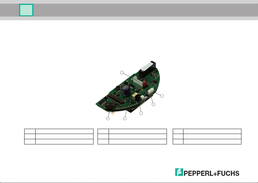
4.1 Displays and operating elements
Illustration41 Displays and operating elements
No. Designation No. Designation No. Designation
1 Bargraph with 10 LEDs 3 IR transmitter 5 Navigation key
2 LED red/green 4 IR receiver 6 Connection plug
Table 4.2 Displays and operating elements
38
Page 10

Radar Motion Sensor RMS-FRW
Product description
4.1.1 Overview of LED displays
Switch-on / initialization
LED red/green Bargraph Description
Flashes red/
green
- The sensor is being initialized.
Standard operation / detection
LED red/green Bargraph Description
Illuminates green - The sensor is ready to operate, no detection.
Illuminates red - Detection by movement detector
Operation with RMS Remote Control
LED red/green Bargraph Description
Flashes 3x green - Command received from remote control
Error
LED red/green Bargraph Description
Flashes red Error code The sensor has identified an error. The bargraph display indicates an error code.
4.2 Scope of delivery
The scope of delivery includes:
• RMS-FRW
• 3 m connection cable with 8-pin connector strip
• Self-adhesive mounting template sticker
• Screws for mounting
• Operating instructions
39
Page 11

Radar Motion Sensor RMS-FRW
Installation
4.3 Accessories
The following products are available as accessories:
No. Designation Illustration Description
1 RMS Remote Control Infrared remote control
2 RMS Weather Cap
Weather cap and mounting bracket for
ceiling mounting
5 Installation
5.1 Storage and transportation
For storage and transport purposes, package the unit using shockproof packaging material and protect it against
moisture. The best method of protection is to package the unit using the original packaging. Furthermore, ensure
that the ambient conditions are within the allowable range.
5.2 Unpacking the device
Check to see that no parts are damaged. In the case of damage, report it to the post office or carrier and notify the
supplier.
Check the scope of delivery against the original purchase order and the shipping documents.
Keep the original packing material in case the device has to be placed into storage or for possible future reshipment.
If you have any questions, contact Pepperl+Fuchs.
40
Page 12

Radar Motion Sensor RMS-FRW
Installation
5.3 Mounting and connecting the device
Positioning the sensor
Make sure that the printed circuit board is fitted horizontally (0°) in the inside of the housing.
The sensing area is 2500 mm x 3500 mm (D x W) at 2200 mm mounting height.
The printed circuit board can be adjusted by a maximum of 10°. (Max. two notches downwards)
Illustration51 Mounting the RMS-FRW
Mounting the RMS-FRW
Proceed as follows to mount the sensor:
1. Open the housing with a slotted screwdriver from below.
An indentation is located underneath the housing.
Do not open the housing from above!
2. Place the template (included with sensor) in desired location.
3. Drill mounting holes.
4. Pull the enclosed cable with the connector side through the provided opening.
5. Mount the base plate using the screws enclosed in the housing.
41
Page 13

Radar Motion Sensor RMS-FRW
Pin-out according 8-pin plug strip
Pin-out according 8-pin plug strip
(Frequency output)
(Relay output)
Pin Signal
Pin Signal
1
2
3
4
5
6
7
8
+12 ... 36 V DC
GND
Relay 1
Relay 1
Relay 2
Relay 2
No Connection
No Connection
Color
Color
white
brown
green
yellow
grey
pink
blue
red
Pin-out according 8-pin plug strip
(Voltage output)
Pin Signal
Color
1
2
3
4
5
6
7
8
+12 ... 36 V DC
GND
Uout +
Uout No Connection
No Connection
No Connection
No Connection
white
brown
green
yellow
grey
pink
blue
red
1
2
3
4
5
6
7
8
+12 ... 36 V DC
GND
Fout +
Uin Uin +
No Connection
No Connection
No Connection
white
brown
green
yellow
grey
pink
blue
red
Installation
Connecting the RMS-FRW
The sensor is supplied with power via the connection plug. It is also possible to directly connect
to the relay contact on the connection plug. Proceed as follows:
1. Connect the cable to the power supply.
2. Insert the socket on the cable into the connection plug on the printed circuit board.
3. Connect the safety sensor terminal on the controller (door control) with the relay contacts or
the corresponding voltage or frequency output of the movement detector. For this, use the
suitable wires of the cable coming from the RMS-FRW.
4. For all further steps, refer to Set-up (see section 6)
5. After completing all the settings for the sensor, push the cover over the base plate. Hook the
cover on to the upper end of the base plate and press the cover until it clicks into place.
The plug has the following pin assignment:
42
Page 14

Radar Motion Sensor RMS-FRW
UP
SELECT
DOWN
Set-up
6Set-up
When switching on the RMS-FRW, make sure to remove all objects in the door area that do not belong in the usual
vicinity of the door.
Set-up
To set-up the sensor, proceed as follows:
1. Switch on the power supply.
2. Set the output movement detector on the RMS-FRW or select the standard profile door
control. (see section 10.1)
3. Set the sensor address.
4. Set the mounting height on the RMS-FRW.
5. Set the movement detection on the RMS-FRW.
6. Check the settings by pacing through the dynamic field.
You can also program the sensor using the remote control with the hood placed in position.
In such a case, the sensor address needs to have been previously set.
7Operation
7.1 Keypad menu operation
7.1.1 General setting instructions
In the keypad menu the sensor can be set by means of the navigation key and the bar graph display.
The sensor function is maintained even in the keypad menu. The programming can be checked immediately.
43
Page 15

Radar Motion Sensor RMS-FRW
Group 1:
Movement detection parameters
Group 3:
General sensor parameters
LED 1: Sensitivity
LED 2: Detection mode
LED 3: Cross traffic suppression
LED 4: Immunity
LED 5: Output hold time
LED 6: Polarity output
LED 1: Sensor address
LED 2: Mounting height
Main menu
UP
SELECT > 2 s
DOWN
Operation
RMS-FRW parameters
7.1.2 Start / end keypad menu
Start the keypad menu by pressing the SELECT key for 2 s. The bar graph display begins to flash.
Exit the keypad menu by pressing the SELECT key for 2 s.
If no setting takes place over a period of 10 minutes, the keypad menu is automatically exited.
7.1.3 Setting parameters
Use the UP and DOWN keys to select and change the parameters.
Use the SELECT key to confirm the set value.
44
Page 16

Radar Motion Sensor RMS-FRW
Operation
1. Selecting the parameter group
The bar graph display shows the selected parameter group by flashing.
Use the UP and DOWN keys to select the parameter group and confirm by pressing the SELECT key.
Movement detection parameters
General sensor parameters
2. Selecting parameters
The bar graph display indicates the parameter selected by flashing.
Use the UP and DOWN keys to select the parameter group and confirm by pressing the SELECT key.
Display Movement detection Sensor general
3. Setting the parameter value
The bar graph display indicates the current value of the selected parameter.
Use the UP and DOWN keys to select the parameter group and confirm by pressing the SELECT key.
Parameter 1 Sensitivity Sensor address
Parameter 2 Detection mode Mounting height
Parameter 3 Cross traffic suppression
Parameter 4 Immunity
Parameter 5 Output hold time
Parameter 6 Polarity output
Parameter 7
Parameter 8
Parameter 9
ex. sensitivity - stage 4
ex. sensitivity - stage 7
45
Page 17

Radar Motion Sensor RMS-FRW
UP
SELECT > 10 s
DOWN
RMS-D-RC
RMS-M-RC
RMS-G-RC
RMS-FRW
Pepperl+Fuchs
RMS-S
RMS-S-FRW
find address
address 1
address 2
address 3
address 4
address 5
RMS-FRW
Operation
7.1.4 Fast entry
You can use the fast entry to change the "Sensitivity of the movement detection" directly.
To edit or display the current parameter value there is no need to change over to the keypad menu.
To do this, proceed as follows:
• The SELECT key shows the current value.
• The UP and DOWN keys immediately change the parameter value.
• The current value is shown for a period of 10 s.
7.1.5 Restoring the factory default settings (RESET)
If the navigation key is kept pressed for a period longer than 10 s, then the parameters are returned
to their default settings, followed by a reset of the sensor.
7.2 Remote control operation
Use the remote control to optimally program the sensor from the ground easily and quickly. The sensor function is
maintained even in programming mode. The programming can be checked immediately.
7.2.1 Establishing the connection
Read the remote control operating instructions before programming.
Switch on the sensor. The green LED lights.
Direct the remote control such that it is aimed directly at to the sensor.
Establishing connection without code
Select sensor "RMS-FRW" Select the address Set the sensor
46
RMS-FRW
movement detection
sensor generally
Page 18

Radar Motion Sensor RMS-FRW
RMS-D-RC
RMS-M-RC
RMS-G-RC
RMS-FRW
Pepperl+Fuchs
RMS-S
RMS-S-FRW
find address
address 1
address 2
address 3
address 4
address 5
RMS-FRW
enter code
sensitivity
detection mode
fade out cross traff.
immunity
output hold time
polarity output
movement detection
read value
1 minim.
2
3
4
5
sensitivity
read value
1 minim.
2
3
4
5
sensitivity
read value
1 minim.
2
3
4
5
sensitivity
Operation
Establishing connection with code
RMS-FRW
movement detection
sensor generally
Select sensor "RMS-FRW" Select the address Enter 4-digit code Set the sensor
When the connection has been established, a selection window with all setting options of the sensor appears.
The black bar marks the current setting.
7.2.2 Setting the sensor
Use the operating buttons to select the required setting based on the indicated values.
Example: set the sensitivity of the movement detection
Select "Sensitivity of the
movement detection"
If the connection is interrupted, a transmission error is indicated. The transmission must be repeated.
The new setting can be checked immediately after the transmission.
Select menu option "Read
value"
The current
value is displayed
Set the value
47
Page 19

Radar Motion Sensor RMS-FRW
installation height
standardprofiles
sensorstate
reset
code
close connection
sensor generally
access with code
lock access
access without code
code
enter code
repeat code
Operation
7.2.3 Address
If several sensors are within range of the remote control, the sensors must be programmed with different addresses.
This setting can only be made with the keypad menu.
7.2.4 Security
Access without code:
Access with the remote control is possible at any time.
Access with code:
The sensor can be secured against unauthorized access with a 4-digit code. The programming mode can then only
be accessed by entering the code.
48
Select "Code" Select "Access
with code"
Enter 4-digit code Repeat
4-digit code
Lock access:
If the sensor is secured with "Lock access", the device is locked. Access with the remote control is no longer possible.
The configuration mode is automatically left 30 minutes after the last transfer. cycling power the sensor is in the "Access without code" state for 30 minutes.
Page 20

Radar Motion Sensor RMS-FRW
Maintenance and repair
8 Maintenance and repair
Maintenance
Conformance to all applicable laws and regulations regarding maintenance must be ensured.
The sensor is largely maintenance-free.
However, periodically check the technical safety of the sensor system for damage to the housing.
The sensor should be checked occasionally for contamination. To clean the sensor, wipe the sensor with a dry or
damp soft cloth at regular intervals. This assures optimal functioning.
The housing is made of plastic. Therefore avoid contact with acetone and cleaning agents containing solvents.
Repairs
If safe operation is no longer possible, the sensor system must be disconnected and protected against accidental
use. In the event of repairs, send the device to Pepperl+Fuchs. Independent interventions and separate modifications are dangerous and will void the warranty and exclude the manufacturer from any liability.
9 Troubleshooting
Interfering influences
• The sensor must be mounted securely and not subject to any vibration.
• The sensor must not be installed behind a cover
• The sensing area should be free of moving objects (ex. fans, plants, trees, flags etc.)
• The sensor should be mounted with suitable rain protection. (For recommended accessories see section 4.3)
• The sensor should not be mounted close to fluorescent lighting
Eliminating interfering influences
Error source Remedy
LED red flashes
The sensor has identified an error. The bargraph display indicates an error
code.
49
Page 21

Radar Motion Sensor RMS-FRW
Appendix
10 Appendix
10.1 Explanation of sensor parameters
10.1.1Movement detection
Sensitivity
Using this sensitivity setting, the size of the sensing area can be changed.
The setting options range from 1 (smallest sensing area) to 10 (largest sensing area).
This setting can be set using the remote control or the keypad menu.
Detection mode
The direction recognition can be changed with the detection mode.
Setting Description
Mono Detects forward and backward movement
Forward Detects movement towards the sensor
Backward Detects movement away from the sensor
This setting can be set using the remote control or the keypad menu.
Suppression of cross traffic
This mode can be used to change the strength of cross traffic suppression. The setting options range from 1 (off),
2 - 5 (low) to 6 - 10 (high). High cross traffic suppression means strong suppression (fade out) of cross traffic.
This setting can be set using the remote control or the keypad menu.
Immunity
In principle, the sensor is immune against any interfering influences. However, special installation situations or major
sources of interference may sometimes cause incorrect triggering. The immunity setting can be used to minimize
various interfering influences (vibrations, reflections, fluorescence lighting etc.).
The setting options range from 1 (off), 2 - 5 (low) to 6 - 10 (high).
This setting can be set using the remote control or the keypad menu.
50
Page 22

Radar Motion Sensor RMS-FRW
Appendix
Output hold time
In the case of the setting "Off", together with the function "Polarity - output", the door could remain open or closed
indefinitely.
Setting Hold time
0 off (no output signal)
10.2s
20.5s
31s
42s
53s
64s
75s
810s
This setting can be set using the remote control or the keypad menu.
Polarity
Using this function, it can be preset whether the output of the movement detector works with active or passive switching during detection.
Output type RMS-FRW with relay RMS-FRW with voltage output RMS-FRW with frequency output
Active
Passive Relay contacts open at detection
Relay contacts closed
at detection
Output voltage = on
at detection
Output voltage = off
at detection
Output frequency = on
at detection
Output frequency = off
at detection
This setting can be set using the remote control or the keypad menu.
51
Page 23

Radar Motion Sensor RMS-FRW
Appendix
10.1.2Sensor general
Sensor address
If several sensors are within range of the remote control, the sensors must be programmed with different addresses
via the keypad menu.
16 fixed sensor addresses are available for selection.
Display Address Display Address
Sensor 1 Sensor 9
Sensor 2 Sensor 10
Sensor 3 Sensor 11
Sensor 4 Sensor 12
Sensor 5 Sensor 13
Sensor 6 Sensor 14
Sensor 7 Sensor 15
Sensor 8 Sensor 16
This setting can only be made with the keypad menu.
Mounting height
For this parameter, set the height of the sensor from the ground up to the bottom edge of the sensor.
The following setting options are possible: 200 - 220 cm / 220 - 240 cm / 240 - 260 cm / 260 - 280 cm / 280 - 300 cm
/ 300 - 320 cm / 320 - 340 cm / 340 - 360 cm / 360 - 380 cm / 380 - 400 cm
This setting can be set using the remote control or the keypad menu.
52
Page 24

Radar Motion Sensor RMS-FRW
Appendix
Standard profile door control
Following the selection of the control system, the pre-defined settings (ex. polarity outputs, test input, etc.) will be
automatically transferred to the sensor.
Please contact us directly, or consult the Internet page www.pepperl-fuchs.com for a list of the pre-defined door control systems with a listing of all settings.
This setting can only be made with the remote control.
Sensor status
The current sensor status can be read by means of this function.
Reset
Using this function, all device parameters are restored to the factory default settings, and then the sensor begins
initialization.
This setting can be set using the remote control or the keypad menu.
Code
Access to the sensor can either be set with code, without code or locked completely.
This setting can only be made with the remote control.
Disconnection
This parameter can be used to immediately disconnect the connection between remote control and sensor.
This setting can only be made with the remote control.
53
Page 25

Radar Motion Sensor RMS-FRW
Appendix
10.2 Overview of sensor parameters
Parameter Value range Default settings
Sensitivity 1- 10 10
Detection mode Mono / forward / backward Forward
Cross traffic suppression
Immunity
Output hold time Off / 0.2 s / 0.5 s / 1 s / 2 s / 3 s / 4 s / 5 s / 10 s 1 s
Movement detection
Polarity Active / passive Passive
Sensor address 1 - 16 1
Mounting height
Restore default settings - -
Sensor general
Access code Off or 4-digit code Off
1 off
2 - 5 low
6 - 10 high
1 - 2 low
2 - 5 medium
6 - 10 high
200 - 220 cm / 220 - 240 cm / 240 - 260 cm /
260 - 280 cm / 280 - 300 cm / 300 - 320 cm /
320 - 340 cm / 340 - 360 cm / 360 - 380 cm /
380 - 400 cm
Table 10.1 Overview of sensor parameters (with factory default settings)
54
1
2
200 - 220 cm
Page 26

Radar Motion Sensor RMS-FRW
Appendix
10.3 Overview of remote control menu structure
sensitivity
read value
1 minim.
2
3
4
5
detection mode
read value
mono
forwards
backwards
fade out cross traff.
read value
1 off
2 minim.
3
4 low
5
immunity
read value
1 minim.
2
3
4
5
ut hold time
outp
read value
off
0.2s
0.5s
1.0s
2.0s
polarity output
read value
active
passiv
movement detection
sensitivity
detection mode
fade out cross traff.
immunity
output hold time
polarity output
Illustration102 Remote control menu structure
Pepperl+Fuchs
RMS-D-RC
RMS-M-RC
RMS-G-RC
RMS-FRW
RMS-S
RMS-S-FRW
RMS-FRW
find address
address 1
address 2
address 3
address 4
address 5
RMS-FRW
movement detection
sensor generally
sensor generally
installation height
standardprofiles
sensorstate
reset
code
close connection
installation height
read value
200 - 220cm
220 - 240cm
240 - 260cm
260 - 280cm
280 - 300cm
standardprofiles
profile 1
profile 2
profile 3
profile 4
profile 5
profile 6
sensorstate
transmission
reset
transmission
code
access with code
lock access
access without code
close connection
transmission
55
Page 27

Radar Motion Sensor RMS-FRW
Appendix
10.4 Technical Data
General specifications
Function principle Microwave module
Detection speed min. 0.1 m/s
Marking CE
Mounting angle 0 ... 10° in steps of 5°
Sensing area 2500 x 3500 mm (D x W) at 2200 mm mounting height and of 0° tilt angle
Operating frequency 24.05 ... 24.25 GHz K-Band
Operating mode Radar Motion Sensor
Transmission power (EIRP) < 20 dBm
Functional safety related parameters
Performance level (PL) PL d
Category Cat. 3
MTTF
d
PFH
d
Diagnostic Coverage (DC) low
Displays/operating elements
Operation indicator LED red/green & LED row green
Operating elements Navigation key
Electrical data
Operating voltage 12 ... 36 V DC
Current Consumption
Power consumption
Switching current 900 mA
FRW/31 output
Output type Relay output
Switching type Active / passive
Signal output 2 relay outputs for dynamic output
Switching voltage 48 V DC / AC
Switching current max. 1 A DC, 0.5 A AC
850 a
6.46 E-8
200 mA at 24 V DC
I0
< 3 W
P0
56
Page 28

Radar Motion Sensor RMS-FRW
Appendix
Switching capacity 30 W DC / 60 VA AC
FRW/163 output
Output type Voltage output
Switching type Active / passive
Signal output Potential-free voltage source
Max. open circuit voltage No movement detection: 10 V DC / movement detection: 500 mV DC
Switching current No movement detection: max. 10 mA at 3.2 V DC / movement detection: < 100 µA
FRW/164 output
Output type Frequency output
Switching type Transistor output (Open Collector)
Signal output Short-circuit proof
Feeding the terminating stage External: 10 V DC ... 36 V DC
Max. residual voltage 2 V DC
Max. output current 50 mA
Pulse/pause ratio 1:1 (deviation max. 10%)
Output frequency 100 Hz
Compliance with standards
Standards
Ambient conditions
Ambient temperature -20 ... 60 °C (253 ... 333 K)
Operating temperature -25 ... 60°C (248 ... 333K)
Storage temperature -30 ... 70°C (243 ... 343K)
Relative humidity max. 90 % non-condensing
Mechanical data
Mounting height max. 4000 mm
Protection category IP54
Connection 8-pin connector strip with 3 m cable
Material
Housing ABS, anthracite
Mass 6.0 oz (140 grams)
EN 60950:2000; EN 60335-1:1994; EN 301489-3 V1.4.1; EN 61000-6-1:2001, EN 610006-2:2001; EN 61000-6-3:2001; EN 61000-6-4:2001 ; EN 300440-2 V1.1.1; AutSchR: 1997
57
Page 29

10.5 Note
58
Radar Motion Sensor RMS-FRW
Appendix
Page 30

FACTORY AUTOMATION – SENSING YOUR NEEDS
Worldwide Headquarters
Pepperl+Fuchs GmbH · Mannheim · Germany
E-mail: info@de.pepperl-fuchs.com
USA Headquarters
Pepperl+Fuchs Inc. · Twinsburg · USA
E-mail: sales@us.pepperl-fuchs.com
Asia Pacific Headquarters
Pepperl+Fuchs Pte Ltd · Singapore
E-mail: sales@sg.pepperl-fuchs.com
www.pepperl-fuchs.com
Subject to reasonable modifications due to technical advances • Copyright PEPPERL+FUCHS • Printed in Germany
DOCT-1507B Part No. 206908
11/2013
 Loading...