

Page 1
RMS-D / RMS-D-RC / RMS-D-NA / RMS-D-RC-NA English
General Information for Your Safety
This device must be installed and maintained only by qualied, trained personnel.
Observe the safety requirements of EN 60950-1. Operate the sensor only with an SELV supply with a limited
output of up to 100 W. Use a T2.5 A fuse, for example, to reliably limit the power output.
Brief Instructions: Radar Motion Sensor for Detecting Persons at Automatic Doors
Scope of Delivery
Quantity Designation
1 Sensor RMS-D...
1 Connection cable with plug
1 Self-adhesive drilling template
2 Screws for mounting
1 Mounting instructions
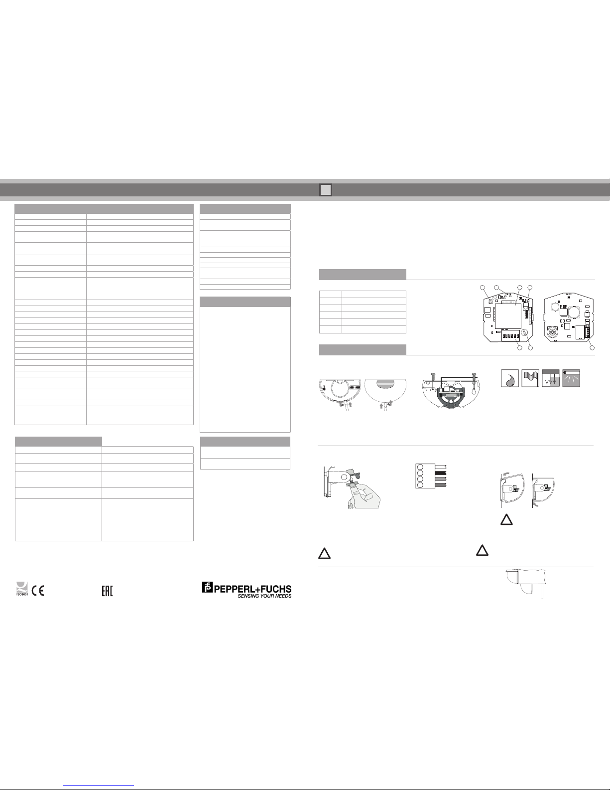
Operating Elements
LED (red/green)
IR receiver
IR transmitter
DIP switches
Potentiometer
Connecting plug
Antenna
Product Information
Connecting the Radar
Connect the cable with the connecting plug:
Opening the Device
Open the housing from below:
Insert the screwdriver into the opening provided
and carefully push open the cover.
Fold up and remove the cover.
Mounting the Device
1. Attach the self-adhesive template
and drill according to the markings on the
template.
2. Pull the cable through the opening provided.
3. Fasten the base plate using the screws
(screws are in the housing).
Installation
Installation Information
• Protect the radar from rain*.
• Avoid placing moving objects in the detection
eld (fans, plants, trees, ags).
• Do not cover the radar. Only install the radar be-
hind appropriate covers. Mechanically operated
drive components may aect the radar.
• Avoid uorescent lights in the detection eld.
* Installation of the RMS Weather Cap is
recommended (see accessories).
Closing the Device
Attach the cover on the top and press down until it
snaps into place.
Turning the Antenna
to change the antenna characteristics
1. Select the shape of the detection area
(narrow or wide).
2. Remove the antenna carefully using two
ngers.
3. Turn the antenna through 90° and re-attach.
Do not touch any electronic components.
Do not use any metallic tools.
!
Technical Data
Functional principle
Microwave module
Detection speed
Min. 0.1 m/s
Marking
CE
Inclination angle
Vertical: 0° – 90° in 10° steps
Horizontal: -30° – +30° in 5° steps
Detection range at installation height
of 2200 mm and 30° inclination angle
Narrow (standard): 2000 x 4500 mm (WxD)
Wide: 4500 x 2000 mm (WxD)
Operating frequency
24.15 GHz – 24.25 GHz K band
NA version (FCC/IC): 24.075 GHz – 24.175 GHz K band
Operating mode
Radar motion sensor
Function indicator
Red/green LED
Operating elements
DIP switch for selecting the mode of operation:
Direction detection, cross-trac suppression,
slow motion, switching mode, size of detection area,
adjuster for fall time
Operating voltage
12 – 36 VDC/12 – 28 VAC
No-load current
< 50 mA at 24 VDC
Power consumption
< 1.2 W at 24 V DC / < 1.7 W at 36 V DC
Switching mode
Active/passive
Signal output
Relay, 1 NO contact/NC contact
Switching voltage
Max. 48 VAC / 48 VDC
Switching current
Max. 0.5 AAC/1 ADC
Switching power
Max. 24 W/60 VA
Fall time
0.2 s – 5 s, adjustable
Ambient temperature
-20° C to 60° C/253 – 333 K
Relative humidity
Max. 90 % without condensation
Mounting height
Max. 4000 mm
Degree of protection
IP 54
Connection
5 m connection cable with plug, 4-pin
(cable is included in the scope of delivery)
Housing material
Polycarbonate (PC), ABS
Mass
130 g
Transmitting power (EIRP)
< 20 dBm
Dimensions excluding securing parts
123 mm (w) x 65 mm (h) x 57 mm (d)
Troubleshooting
Fault Corrective action
Door is detected. Decrease the size of the detection area.
Change inclination angle.
LED not lit up.
No power supply, device not functioning.
Sensor reacts to the slightest inuences
such as rain, vibrations, or reections.
Door opens for no apparent reason.
Increase immunity,
decrease the size of the detection area.
Potentiometer does not respond Operation with remote control is switched on.
Set DIP switch 6 to the UP position.
Remote control does not respond Operation with the DIP switch and potentiometer
is switched on. Set DIP switch 6 to the DOWN
position.
Device is locked. Switch the operating voltage
o and on again. The sensor can now be congured without a code for 30 minutes.
Check the remote control battery.
Factory Settings
Function
Setting
DIP switches Switch 1 – 5: up
Switch 6: down
Detection area size Potentiometer:
Center position
Remote control: 9
Inclination angle 15°
Direction detection Forward
Fall time 1 s
Relay contact Active
Cross-trac
suppression
Potentiometer: o
Remote control: 1
Immunity 1
Slow motion O
Accessories
RMS
Remote Control
Remote control
RMS Weather Cap
Mounting set and weather
protective cover
Conformity with Standards
EU conformity: Pepperl+Fuchs GmbH hereby
declares that the radio system types RMS-D
and RMS-D-RC comply with Directive 2014/53/
EU.
The full declaration of conformity is available at
www.pepperl-fuchs.com.
US conformity: The products RMS-D-NA and
RMS-D-RC-NA are compliant with Part 15 of the
FCC regulations.
Canada conformity: The products RMS-D-NA
and RMS-D-RC-NA contain an IC-approved
component.
IMPORTANT! The EU-compliant devices must
not be marketed in the United States/Canada
and the US/Canada-compliant devices must not
be marketed in Europe!
1 2
OPEN
3 4 5 6
1 7
4
5
6
23
Mounting options
Important: Do not open the housing from the top.
1
2
3
4
- Wall mounting with base plate
- Wall mounting with weather cap using base plate
- Ceiling mounting with base plate
!
World Headquarters
Pepperl+Fuchs GmbH Lilienthalstr. 200
68307 Mannheim . Germany
Email: FA-info@de.pepperl-fuchs.com
USA Headquarters
Pepperl+Fuchs Inc . Twinsburg . USA
Email: FA-info@us.pepperl-fuchs.com
Asia Pacic Headquarters
Pepperl+Fuchs Pte Ltd . Singapore 139942
Email: FA-info@sg.pepperl-fuchs.com
www.pepperl-fuchs.com
DOCT-1544G
Pepperl+Fuchs GmbH is certied according to ISO 9001. Item no. 215075 02/2018
Connector Assignment for RMS-D/RMS-D-RC:
AC/DC supply (white)
AC/DC supply (black)
Relay contact 1 (red)
Relay contact 2 (green)
Connector Assignment for RMS-D-NA/RMS-D-RC-NA:
AC/DC supply (red)
AC/DC supply (black)
Relay contact 1 (white)
Relay contact 2 (green)
!
Before switching on the device,
remove all objects from the door area that
do not normally belong there.
To meet UL508 requirements, a 2.5 A slow-blow fuse
should be used between the device and the power
supply.
for RMS-D-RC
for RMS-D; RMS-D-RC
Page 2
RMS-D / RMS-D-RC / RMS-D-NA / RMS-D-RC-NA
Monitoring time/sensitivity
1 second/decreasing
3 seconds/decreasing
5 seconds/
constant maximum sensitivity
LED Status Indicator
Color Indicator Status
G
Green
Device ready for
operation
R
Red Detection active
G
Green ashing Command received
R
Red ashing Fault
R/G
Red/green
ashing
Initialization
after switching on
Detection Capabilities
Direction Detection Slow Motion (Turtle Mode)
Detection of the smallest movements
No direction detection
Door closed setting (green LED)
Door opens when a slow-moving object
approaches that would not be detected
with standard detection
Door open setting (red LED)
The door closes if no movement is detected within the set monitoring time.
With direction detection
forward (toward the radar)
With direction detection
backward (away from the radar)
Cross-trac suppression
Immunity (1...7)
5
G 2 2
5
1. Switch DIP switch 5.
The LED ashes green.
2. Switch DIP switch 2.
3. Change the sensitivity of the immunity using
the potentiometer.
The LED indicates the set immunity.
4. Reset DIP switch 2.
The settings are saved.
5. Reset DIP switch 5.
Fall Time (Output)
5
G 1 1
5
1. Switch DIP switch 5.
The LED ashes green.
2. Switch DIP switch 1.
3. Change the fall time of the relay using
the potentiometer. The relay will then be
continually opened and closed with the set
fall time. The LED changes from green to red
accordingly.
4. Reset DIP switch 1.
The settings are saved.
5. Reset DIP switch 5.
Restoring Factory Settings
5
G 4 R 4
5
1. Switch DIP switch 5.
The LED ashes green.
2. Switch DIP switch 4.
The LED ashes red.
3. Reset DIP switch 4.
The radar is reset to the factory settings and
restarted.
4. Reset DIP switch 5 after the end of the
initialization period.
Switching on the Mode
During the initialization period you can switch on
the additional functions mode.
To do this, switch DIP switch 5. The LED ashes
green. Congure additional function and reset
DIP switch 5.
DIP switch 6 must be in the UP position.
Remember the position of the potentiometer
so that you can reset it to the original setting
if required.
Size of Detection Area for Slow Motion
(Turtle Mode) Door Open
5
G 3 1 1 3
5
1. Switch DIP switch 5.
The LED ashes green.
2. Switch DIP switch 3.
3. Switch DIP switch 1.
4. Change the size of the detection area using
the potentiometer.
5. Reset DIP switch 1.
6. Reset DIP switch 3.
The settings are saved.
7. Reset DIP switch 5.
Size of Detection Area for Slow Motion
(Turtle Mode) Door Closed
5
G 3 2 2 3
5
1. Switch DIP switch 5.
The LED ashes green.
2. Switch DIP switch 3.
3. Switch DIP switch 2.
4. Change the size of the detection area using
the potentiometer.
5. Reset DIP switch 2.
6. Reset DIP switch 3.
The settings are saved.
7. Reset DIP switch 5.
Additional Functions
5 G ...
5
Immunity (1...7)
Immunity can be used to minimize interference
such as rain, vibrations, and reections.
1 = Low immunity
7 = High immunity
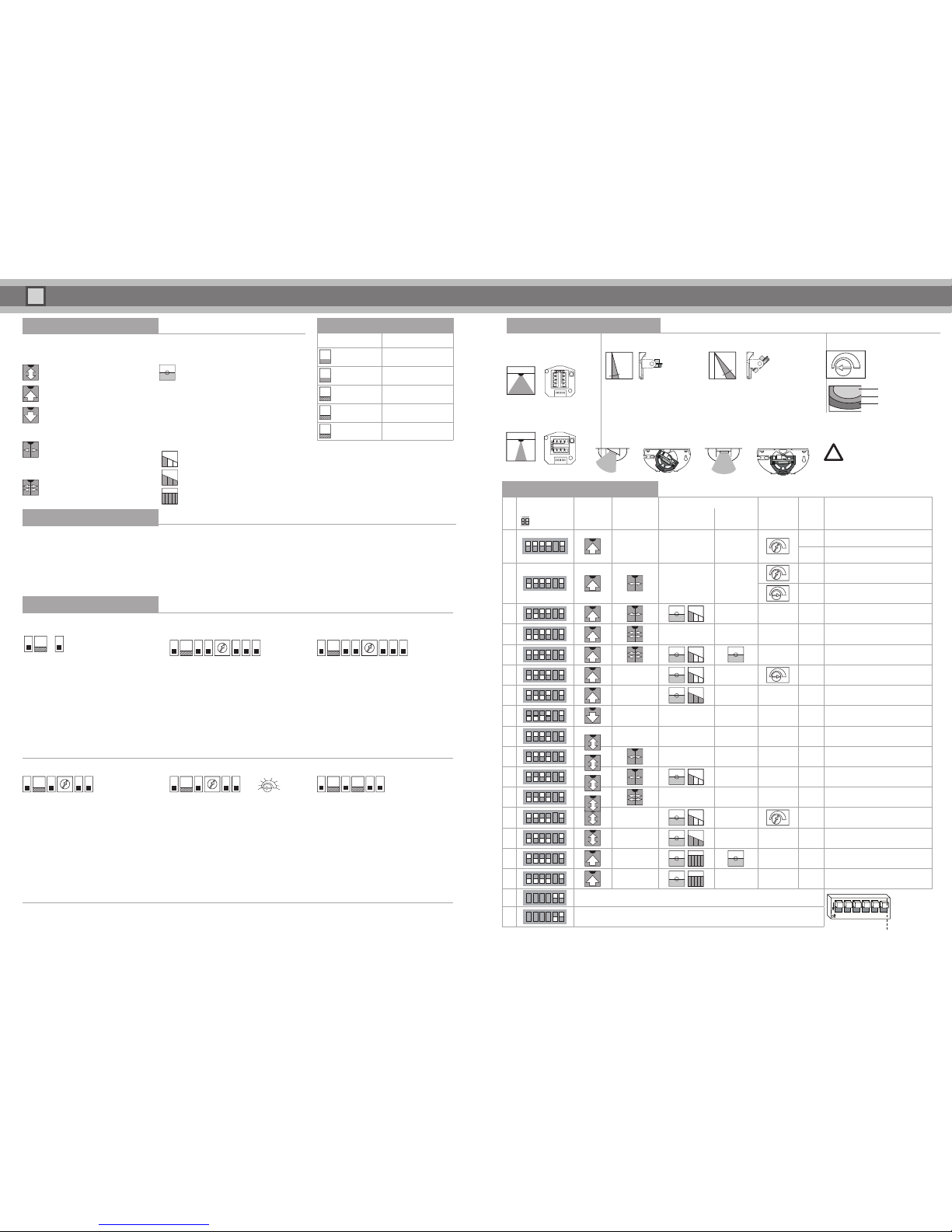
DIP Switch Settings
Check the Setting by Walking Within Range of the Sensor
No.
DIP
¨
=DIP switch
Direction
Detection
Cross-
trac
Suppression
Slow motion (Turtle Mode)
Detection
Area Size
Fall
Time Application ExampleDoor Open
Door
Closed
1 – – –
1 s Standard
0.2 s Porch
2 – –
0.5 s Pavement
1 s High mounting (optional, wide area)
3
–
4 – –
5
6 –
– 1.5 s Supermarket (optional, wide area)
7 –
–
8 – – –
9 – – –
10 – –
11
–
12 – –
13 –
– 2 s Retirement home (optional, wide area)
14 –
–
15 –
16 –
–
Relay contact is active during detection (N.O.)
123456
DIP 6 is only available in RC versions
Relay contact is passive in the event of detection (N.C.)
Detection Field Settings
Antenna Characteristics Inclination Angle Detection Area Size
0 degrees 40 degrees
The potentiometer can
be used to change the
size of the detection area.
The position can be changed in 10° steps. To do so, hold the PCB at the side,
turn toward the front and move to the required position. The factory setting is 15°.
Inclined Detection Area
The PCB can be turned in 5° steps so that it is inclined by +/-30°.
Some installation situations
may limit the adjustment options
and the functions of the sensor.
After applying the operating voltage, the hardware and software are initialized. This process takes 10 seconds. The LED ashes red/green.
Congure the radar. Check the settings by walking within range of the radar. You can only congure additional functions during the initialization period.
Commissioning
0,2 s
0,5
s
1,0 s
1,5 s
2,0 s
3,0 s
4,0
s
5,0 s
Use with swing doors:
The sensor can be used on swing doors. Install the sensor approx. 20 – 30 cm above the door edge on the door hinge side and activate the cross-trac
suppression. The closing door leaf is then not detected.
1 2 3 4 5 6
Wide (standard)
Width: 4.50 m / depth: 2.00 m
Narrow (turn antenna 90°)
Width: 2.00 m / depth: 4.50 m
Min. (1)
50 %
Max. (16)
1 = Smallest detection area
16 = Largest detection area
!
DIP switch 1: Fall time setting (output)
DIP switch 2: Immunity setting
DIP switch 3 + 1: Setting for size of detection area, slow motion (turtle mode) — door open
DIP switch 3 + 2: Setting for size of detection area, slow motion (turtle mode) — door
closed
DIP switch 4: Restore factory settings (RESET)
DIP switch 5: Activation of additional functions menu
DIP switch 6: Must always be in the ON position
Low cross-trac (1...5)
Door remains closed with low
cross-trac
Heavy cross-trac (6...10)
Door remains closed with heavy
cross-trac
min. max.
 Loading...