

Page 1
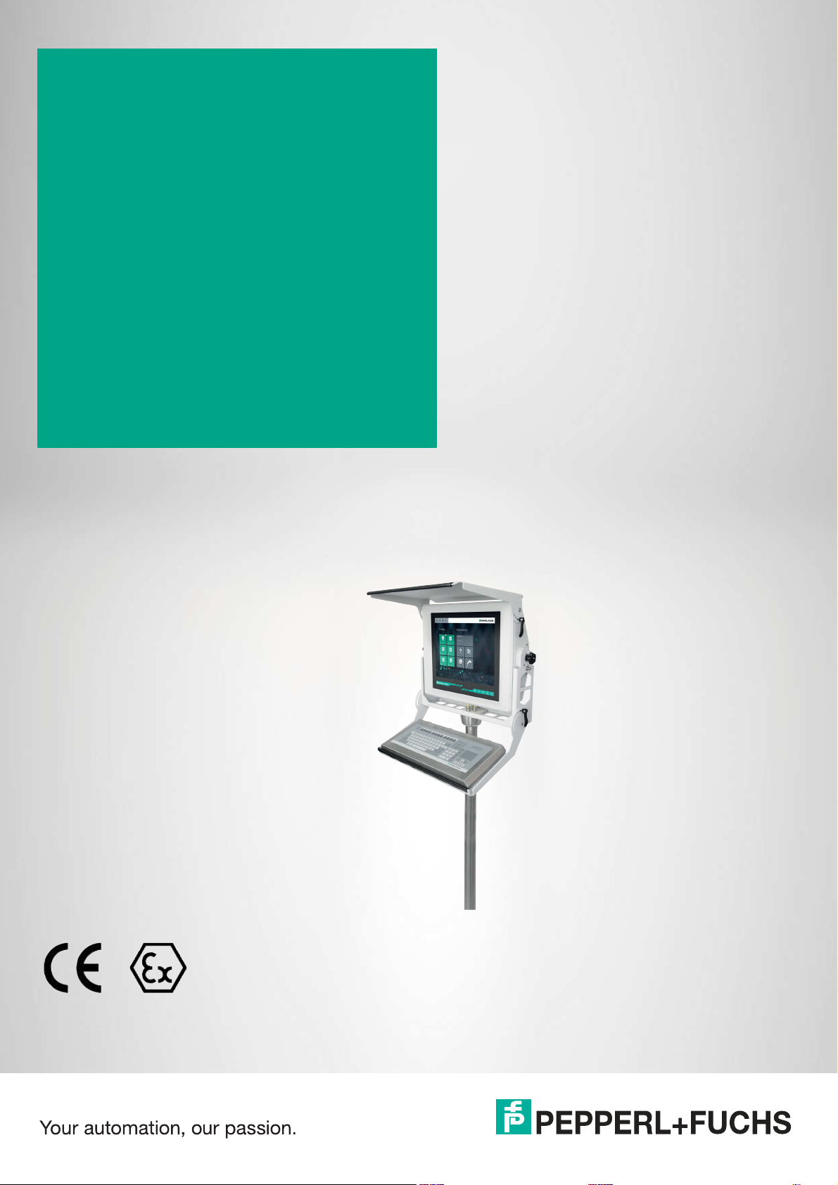
VisuNet IXD
RM-IXD2100-19U*
PC-IXD2100-19U*
Manual
Page 2

With regard to the supply of products, the current issue of the following document is applicable: The
General Terms of Delivery for Products and Services of the Electrical Industry, published by the Central
Association of the Electrical Industry (Zentralverband Elektrotechnik und Elektroindustrie (ZVEI) e.V.)
in its most recent version as well as the supplementary clause: "Expanded reservation of proprietorship"
Worldwide
Pepperl+Fuchs Group
Lilienthalstr. 200
68307 Mannheim
Germany
Phone: +49 621 776 - 0
E-mail: info@de.pepperl-fuchs.com
North American Headquarters
Pepperl+Fuchs Inc.
1600 Enterprise Parkway
Twinsburg, Ohio 44087
USA
Phone: +1 330 425-3555
E-mail: sales@us.pepperl-fuchs.com
Asia Headquarters
Pepperl+Fuchs Pte. Ltd.
P+F Building
18 Ayer Rajah Crescent
Singapore 139942
Phone: +65 6779-9091
E-mail: sales@sg.pepperl-fuchs.com
https://www.pepperl-fuchs.com
Page 3

VisuNet IXD
Contents
1 Introduction................................................................................................................ 4
1.1 Content of this Document............................................................................. 4
1.2 Target Group, Personnel ............................................................................... 4
1.3 Symbols Used ................................................................................................ 4
2 Product Description ..................................................................................................6
2.1 Overview......................................................................................................... 6
2.2 Technical Specifications ............................................................................... 7
2.3 Dimensions................................................................................................... 10
2.4 Scope of Delivery......................................................................................... 12
2.5 Disposal........................................................................................................ 12
3 Mechanical Installation ........................................................................................... 13
3.1 Conditions of Safe Use................................................................................ 13
3.2 General Installation Information ................................................................13
3.3 Installation Environment............................................................................. 14
3.4 Preparing the IXD......................................................................................... 15
3.5 Yoke Mount Installation with Pedestal ....................................................... 15
3.5.1 Preparation for Floor Mounting ........................................................ 15
3.5.2 Preparing the Pedestal..................................................................... 16
3.5.3 Attaching the IXD to the Yoke and Pedestal...................................... 17
3.5.4 Installing the Keyboard Tray Kit ........................................................ 24
3.5.5 Installing the Sunshield Kit ............................................................... 26
3.6 Panel Mount Installation .............................................................................28
3.7 Wall Mount Assembly.................................................................................. 29
3.8 AG1 Assembly.............................................................................................. 31
3.8.1 Preparation for Floor Mounting with AG1 Housing ........................... 31
3.8.2 Preparing the StandardLine Pedestal .............................................. 32
3.8.3 Attaching the Pedestal to the Housing ............................................. 36
3.8.4 AG1 Housing Assembly................................................................... 39
3.8.5 Opening the AG1 Housing ............................................................... 40
3.8.6 Grounding the AG1 Housing to the Pedestal.................................... 41
3.8.7 Mounting the Keyboard.................................................................... 45
4 Appendix .................................................................................................................. 47
4.1 Accessories.................................................................................................. 47
2020-04
3
Page 4
VisuNet IXD
Introduction
1 Introduction
1.1 Content of this Document
This document contains information that you need in order to use your product throughout the
applicable stages of the product life cycle. These can include the following:
• Product identification
• Delivery, transport, and storage
• Mounting and installation
• Commissioning and operation
• Disposal
Note
This document does not substitute the instruction manual.
Note
For full information on the product, refer to the instruction manual and further documentation on
the Internet at www.pepperl-fuchs.com.
The documentation consists of the following parts:
• Present document
• Instruction manual
• Datasheet
Additionally, the following parts may belong to the documentation, if applicable:
• EU-type examination certificate
• EU declaration of conformity
• Attestation of conformity
• Certificates
• Control drawings
• Additional documents
1.2 Target Group, Personnel
Responsibility for planning, assembly, commissioning, operation, maintenance, and dismounting lies with the plant operator.
Only appropriately trained and qualified personnel may carry out mounting, installation, commissioning, operation, maintenance, and dismounting of the product. The personnel must have
read and understood the instruction manual and the further documentation.
Prior to using the product make yourself familiar with it. Read the document carefully.
1.3 Symbols Used
This document contains symbols for the identification of warning messages and of informative
messages.
4
2020-04
Page 5
VisuNet IXD
Introduction
Warning Messages
You will find warning messages, whenever dangers may arise from your actions. It is mandatory
that you observe these warning messages for your personal safety and in order to avoid property damage.
Depending on the risk level, the warning messages are displayed in descending order as follows:
Danger!
This symbol indicates an imminent danger.
Non-observance will result in personal injury or death.
Warning!
This symbol indicates a possible fault or danger.
Non-observance may cause personal injury or serious property damage.
Caution!
This symbol indicates a possible fault.
Non-observance could interrupt the device and any connected systems and plants, or result in
their complete failure.
Informative Symbols
Note
This symbol brings important information to your attention.
Action
This symbol indicates a paragraph with instructions. You are prompted to perform an action or
a sequence of actions.
2020-04
5
Page 6
VisuNet IXD
Product Description
2 Product Description
2.1 Overview
The VisuNet IXD RM-IXD2100-19U* and PC-IXD-2100- 19U* are ATEX/IECEx certified
devices intended for use in potentially explosive atmospheres, such as Zones 1/21.
The VisuNet IXD serves as a thin client- or PC-based operator workstation that uses standard
Ethernet technology to transmit process information from a process control or manufacturing
execution system into hazardous areas.
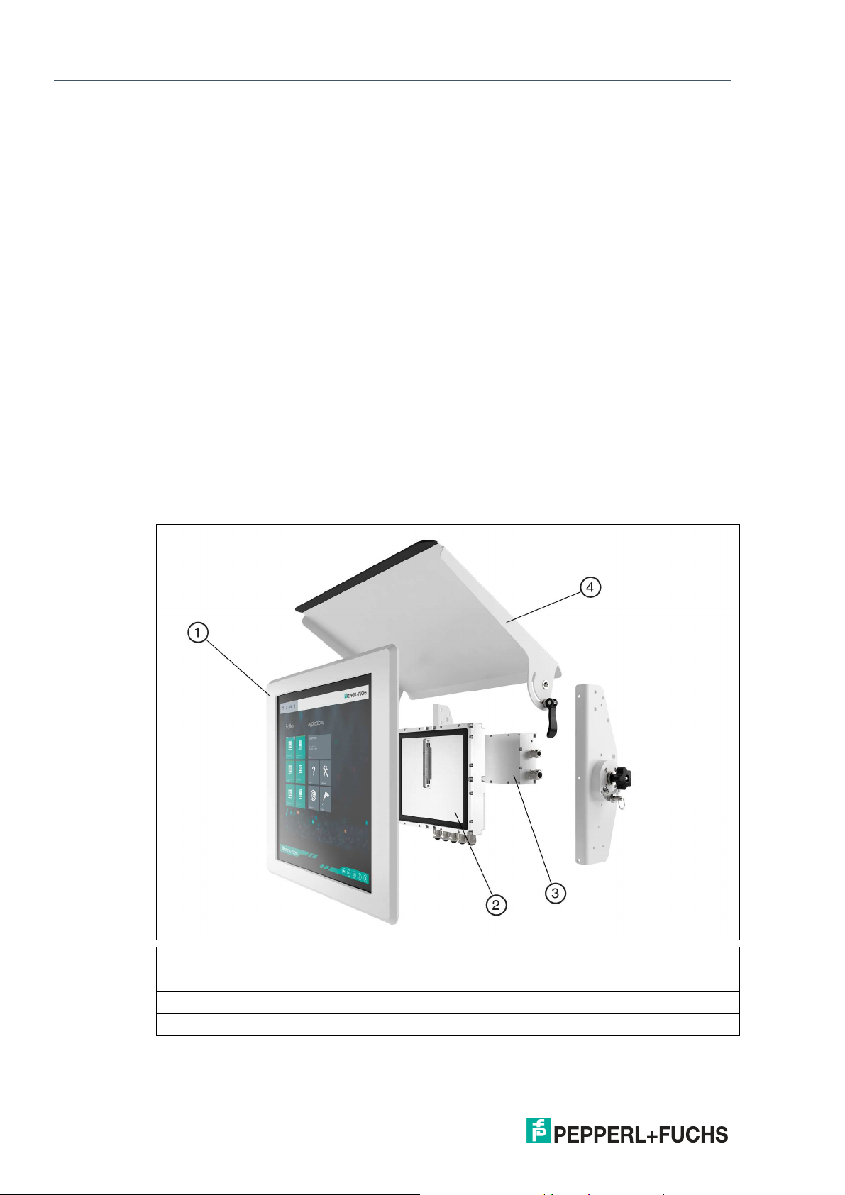
The assembly consists of several core devices that can be replaced by customers:
• The display unit DPU2100-* is a display panel with optional 10-finger multi-touch sensors.
The display and touch sensors are optically bonded with the hardened front glass.
• The thin client unit TCU1100-* is a computing unit that runs the latest Pepperl+Fuchs RM
Shell 5x or RM Shell 4x firmware. TCUs allow connectivity to various host systems in the
safe area using standard Ethernet technology. For more information on RM Shell, visit
www.pepperl-fuchs.com/RM-SHELL.
• The computing unit PCU1100-* runs an open Microsoft® Windows® operating system,
allowing installation of any software, such as SCADA packages.
• The power supply unit PSU1100-* provides the above-listed devices with 24 V DC power.
It is available in DC and AC versions.
VisuNet IXD System Components
1 DPU
2 TCU/PCU
3 PSU
4 Optional sunshield
2020-04
6
Page 7
VisuNet IXD
Product Description
Several mounting options are available:
• Aluminum bezel prepared for yoke mount
• Aluminum bezel prepared for wall/VESA mount
• Aluminum bezel prepared for panel mount
• Installed into EX1 housing AG1 (SS304) front opening, for pedestal/ceiling/wall-arm
The above-listed bezel options require additional mounting kits. These kits must be ordered
separately.
Note
For a description of the product model nomenclature, view the VisuNet IXD PC or RM product
datasheet on www.pepperl-fuchs.com.
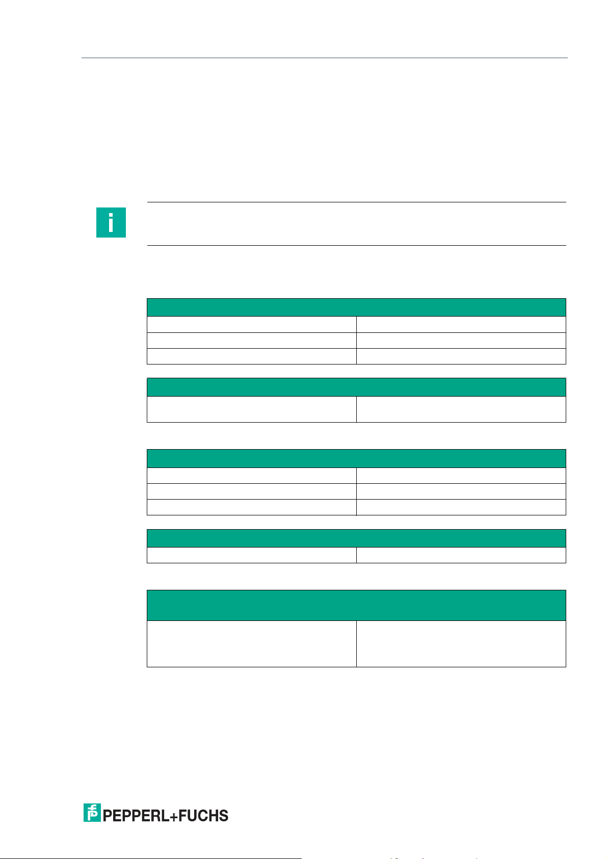
2.2 Technical Specifications
Technical Data RM-IXD*
Hardware
Processor Intel® Atom™ Bay Trail E3827 1.75 GHz
RAM 2048 MB DDR3L
Mass storage 32 GB industrial grade MLC SSD
Software
Operating system VisuNet RM Shell 5.x (based on Windows 10
Technical Data PC-IXD*
Hardware
Processor Intel® Atom™ Bay Trail E3845 1.91 GHz
RAM 4096 MB DDR3L
Mass storage 128 GB SSD
Software
Operating system Windows® 10 IoT Enterprise LTSB
Technical Data RM-IXD* and PC-IXD*
Supply
Power consumption AC:
IoT LTSB)
115/230 V AC, 1.5 A max, 50/60 Hz
DC:
18 ... 36 V DC, 5.3 A max
2020-04
7
Page 8
VisuNet IXD
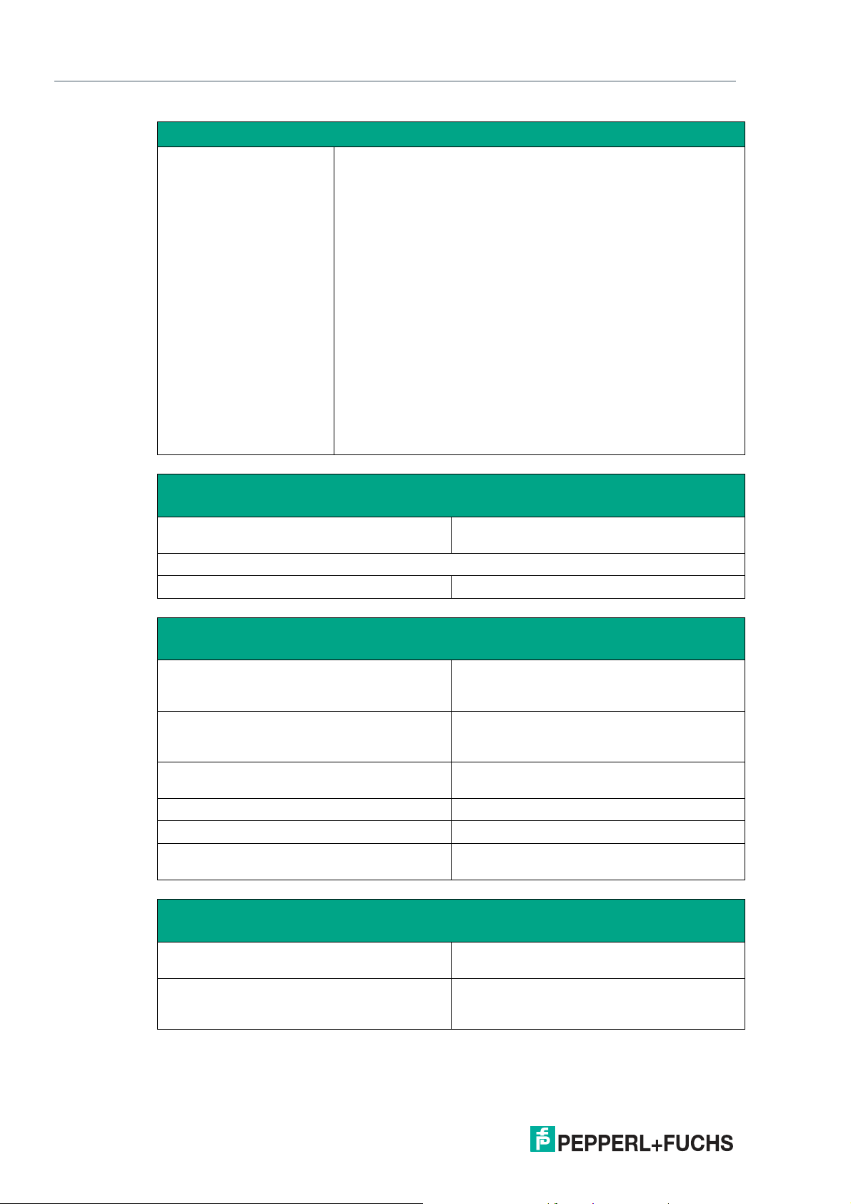
Product Description
Interface
Interface type Pepperl+Fuchs interface v1.0 for display units
1 x Ethernet 100/1000BASE-TX (Ex e) or
1 x fiber optic 1000BASE-SX (Multimode) or
1 x fiber optic 1000BASE-LX (Singlemode)
1 x USB 2.0 (Ex e)
2 x USB 1.1 (Ex i; intended for Pepperl+Fuchs keyboard and
mouse)
1 x DC or AC power in (via power supply unit)
Optional:
1 x barcode reader interface Pepperl+Fuchs Pscan-D/B (Ex i)
"interface 3": 1 x barcode reader interface for wired 1-D scanners
IDM-160-D*, IDM-Z1-160-D-* and base station IDMx61-B-* and
IDM-Z1-x61-B-* (Ex i)
"interface 4": 1 x barcode reader interface for wired 2-D Scanner
IDM-Z1-260-D-* (Ex i)
"interface 5": 1 x RS-232 interface with Power Supply for miscellaneous devices and peripherals (Ex i)
1 x RS-232 (Ex e)
1 x RS-485 (Ex e)
1 x Ethernet 100/1000Base-TX (Ex e)
Electromagnetic compatibility
Directive 2014/30/EU EN 61326-1:2013 (industrial locations)
RoHS
Directive 2011/65/EU (RoHS) EN 50581:2012-09
Ambient conditions
Operating temperature -20 ... 60 °C (-4 ... 140 °F)
Storage temperature -20 ... 60 °C (-4 ... 140 °F)
Relative humidity 93% at 40°C, non-condensating, according to
Altitude Operating altitude max. 2000 m
Shock resistance 3 shocks 20 g , 11 ms all axis, IEC 60068-2-27
Vibration resistance 5 ... 500 Hz, +/- 0.075 mm , 1.5 g, 10 cycles
EN 61000-6-4:2007+A1:2011
Installed in AG1 housing: -20 ... 50 °C (-4 ...
122 °F)
Installed in AG1 housing: -20 ... 50 °C (-4 ...
122 °F)
EN60068-2-78
per axis according to EN60068-2-6
Mechanical specifications
Degree of protection IP66 (individual components and entire sys-
Material Panel: anodized aluminum (TCU, PSU), pow-
tem with housing)
der coated aluminum (DPU)
Bezel: powder coated aluminum
2020-04
8
Page 9
VisuNet IXD
Product Description
Mechanical specifications
Mass panel with DC: 22 kg , panel with AC: 23 kg ,
Dimensions panel with DC: 542 mm x 460 x 132 mm
Note
For more technical information such as electrical data and connection details, refer to the
manuals and instruction manuals of the individual components:
• Display Unit DPU2100-J1*
• AC Power Supply Unit PSU1100-J1-AC-N0
• DC Power Supply Unit PSU1100-J1-DC-N0
• Thin Client Units TCU1100-J1-*
• Computing Units PCU1100-J1-*
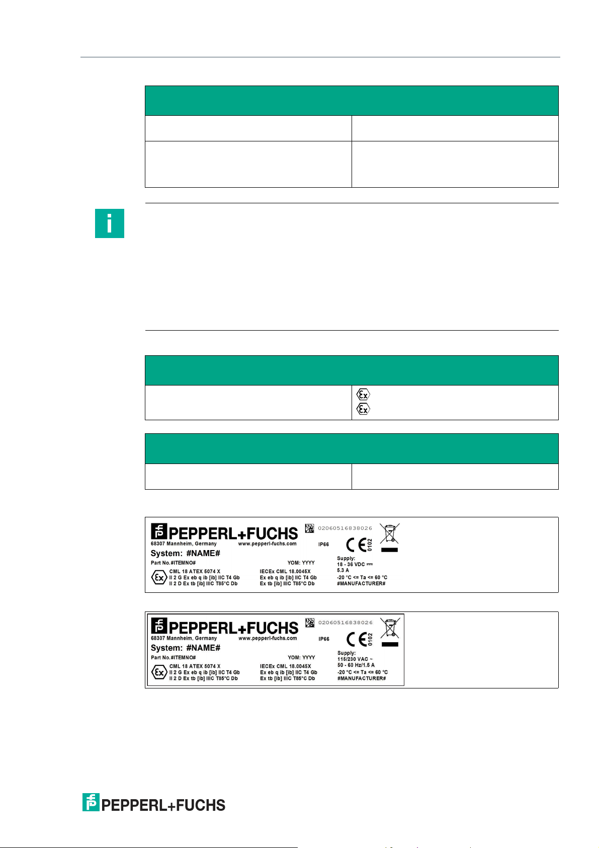
Marking
ATEX
RM-IXD2100-J1-* / PC-IXD2100-J1-*
system housing AG1: 19 kg
panel with AC: 542 mm x 460 mm x 149 mm
panel with housing: 582 mm x 490 mm x 224
mm
II 2G Ex eb q ib [ib] IIC T4 Gb
II 2D Ex tb [ib] IIIC T85°C Db
IECEx
RM-IXD2100-J1-* / PC-IXD2100-J1-* Ex eb q ib [ib] IIC T4 Gb
Ex tb [ib] IIIC T85°C Db
DC Version Label
AC Version Label
2020-04
9
Page 10
VisuNet IXD
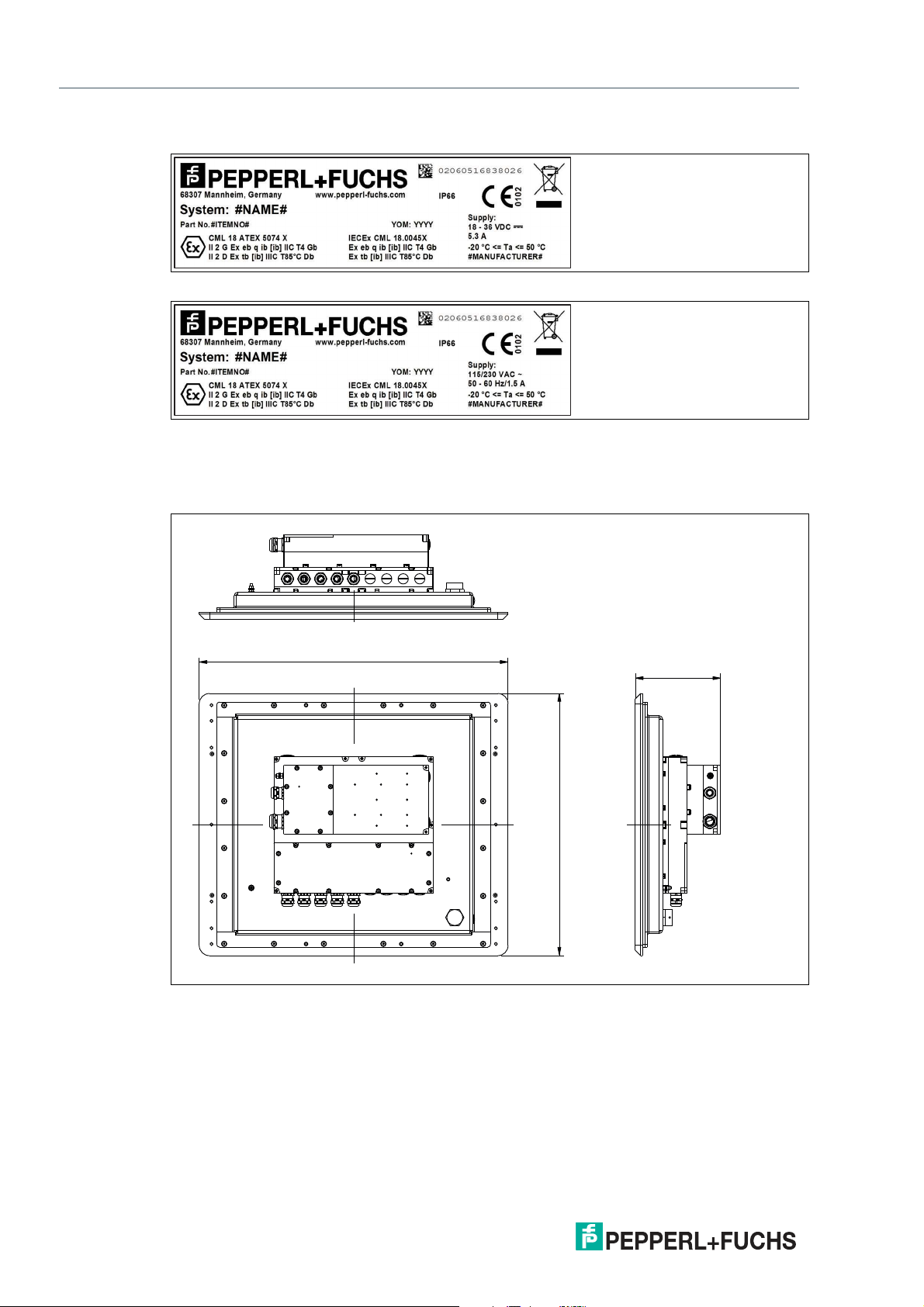
542
149.2
460
Product Description
Label for DC Version in AG1 Housing
Label for AC Version in AG1 Housing
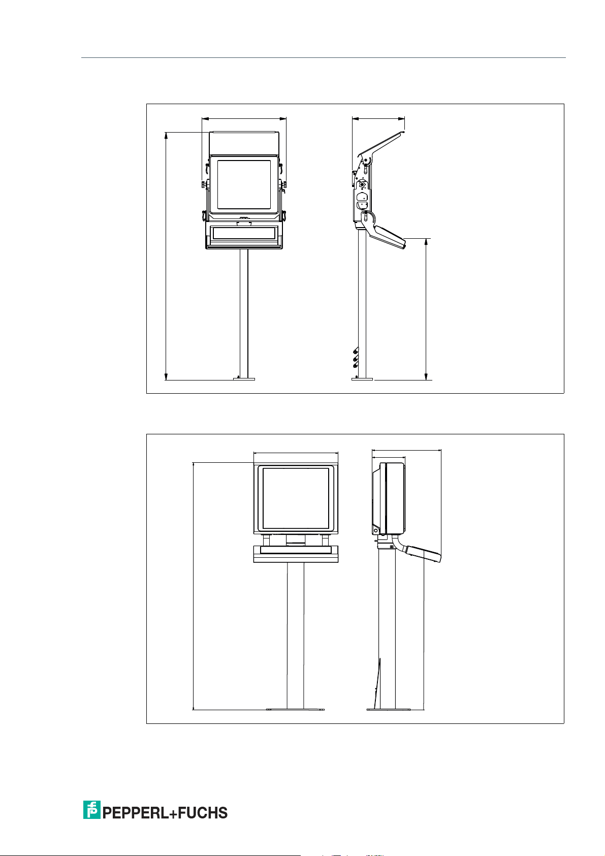
2.3 Dimensions
Panel Dimensions with Bezel
10
Figure 2.1 Panel cut-out dimensinons with bezel
2020-04
Page 11
VisuNet IXD
663
1953
404
1114
582
1703
236
472
1080
Product Description
Yoke-Mount Dimensions
Figure 2.2 Yoke-mount dimensions with optional sunshield and keyboard tray
Dimensions with AG1 Housing and Pedestal
Figure 2.3 Dimensions with AG1 housing and pedestal
2020-04
11
Page 12

VisuNet IXD
Product Description
2.4 Scope of Delivery
The items included with delivery vary depending on the options selected. See the mechanical
installation chapters in this manual as well as the IXD and component datasheets on www.pepperl-fuchs.com for information about available options.
2.5 Disposal
Follow all local and any other requirements for disposing of electronic equipment. When disposing of any system component, mark VOID across all certification labels.
12
2020-04
Page 13
VisuNet IXD
Mechanical Installation
3 Mechanical Installation
3.1 Conditions of Safe Use
• The display does not pose an electrostatic discharge hazard under normal use condi-
tions. Use only water damp cloth and allow to air dry for cleaning device. Do not use or
install in high charge areas. See IEC 60079-32-1 for further information.
• In hazardous dust environment, regularly remove dust from the display unit to prevent
excessive temperature rise. See certificate for full information.
• The device shall be installed such that risk of high impact energy on display glass is con-
sidered to be low.
• The intrinsically safe circuits are connected to earth. Along the intrinsically safe circuits
potential equalization must exist.
3.2 General Installation Information
Observe the following requirements when installing the system components.
• The equipment must be installed by competent personnel in accordance with the instruc-
tions. National laws and regulations must be observed.
• The building installation must provide a 20 A overcurrent protection.
• The installer must make a readily accessible disconnect device available.
• The safety of any system incorporating the power supply unit is the responsibility of the
assembler of the system.
Warning!
Risk of injury
Lifting the device on your own may lead to injury.
Warning!
Strength of installation location and hardware
The installation location and hardware used to permanently secure the completed system to a
floor, wall, or ceiling shall be capable of supporting 4 times the total weight of the completed
system. It is the installer's responsibility to properly select the hardware and fasteners that are
appropriate for the installation location.
Note
Installation steps vary depending on the options and accessories selected. The below
instructions cover the following installation scenarios:
• Yoke mount with pedestal (including assembly of the optional sunshield and keyboard tray
accessories)
• Panel mount
• Wall mount
• Installation into AG1 housing
2020-04
13
Page 14
VisuNet IXD
Mechanical Installation
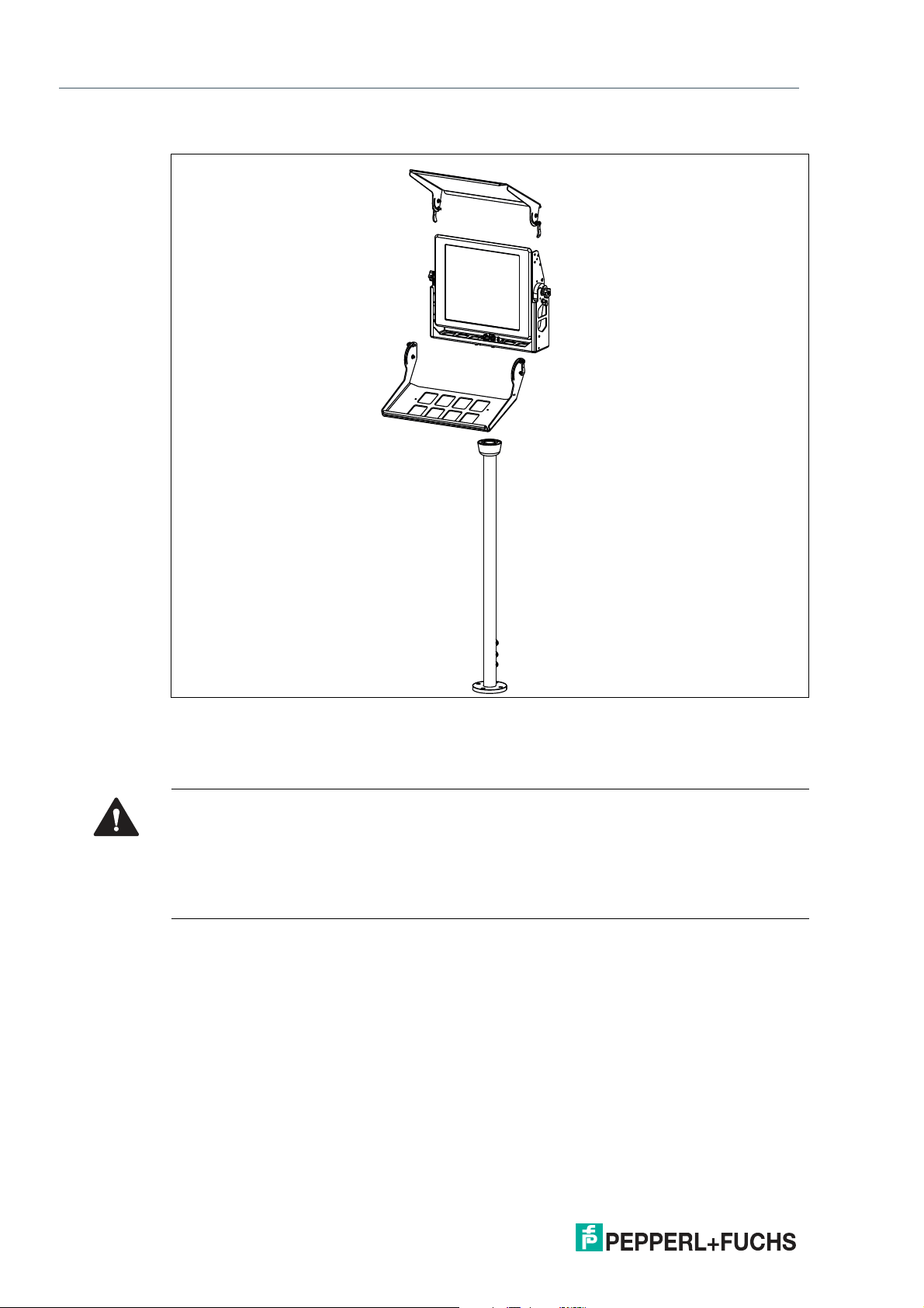
System Installation Example
Figure 3.1 Exploded view of system installation—yoke mounted with pedestal, optional keyboard tray,
and optional sunshield.
3.3 Installation Environment
Caution!
Exposure to direct sunlight and wind
Exposure to direct sunlight may heat the device beyond the maximum permitted operating temperature. Wind may cool down the device and thus impact the minimum operating temperature.
Protect the device from direct sunlight. Consider the impact of wind exposure on the specified
operating temperature range.
The VisuNet IXD product line is designed for outdoor applications. Ensure that the application
is within the specified operating temperature. Any environmental conditions that go along with
the operating temperature range and IP class 66 are suitable for the rugged workstation.
Follow the below steps to protect the device from potential failure:
• Install the device in a location that does not receive extended exposure to saltwater or
associated vapor and mist.
• To maintain the specified operating temperature, install the device in a shaded environ-
ment. Avoid direct sunlight on the IXD display, components, and housing.
• If the available shade is insufficient, the optional sunshield can provide protection. If the
sunshield is insufficient, contact Pepperl+Fuchs to find an engineered solution that provides enough mechanical protection against sunlight.
14
2020-04
Page 15
VisuNet IXD
61.1
18
125
Mechanical Installation
3.4 Preparing the IXD
The VisuNet IXD comes pre-assembled and consists of the core components display unit,
power supply unit, and thin client unit / power supply unit.
Warning!
Risk of injury
Handling the devices with bare hands may cut fingers, hands, or wrists.
Wear gloves at all times during the installation process.
Warning!
Risk of injury
Lifting the IXD housing on your own may cause injury.
Warning!
Danger resulting from scratched display unit screen
Scratches on a display unit front screen weaken the glass structure and may result in broken
glass. Explosion protection is no longer ensured if a display unit with a scratched screen is
used.
NEVER use a display unit with a scratched front screen in a hazardous area. If the surface is
damaged in any way, return the display unit to Pepperl+Fuchs at once and replace it with a new
one.
3.5 Yoke Mount Installation with Pedestal
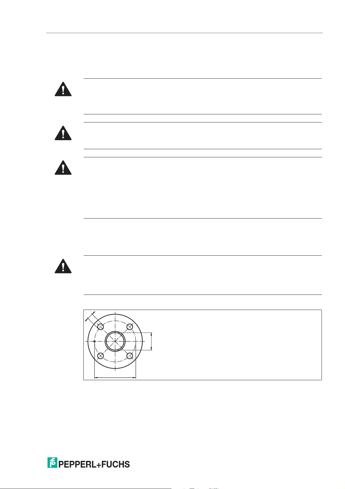
3.5.1 Preparation for Floor Mounting
Warning!
Proper installation on the floor
It is the installer's responsibility to select a suitable location with sufficient strength to hold the
equipment. It is the installer's responsibility to select the proper screws based on the installation conditions.
Yoke Pedestal Hole Pattern
2020-04
15
Page 16

VisuNet IXD
Mechanical Installation
3.5.2 Preparing the Pedestal
For floor mounting with a yoke bracket, the preferred pedestal option is PEDESTAL-XX00-1243-304-TRN-N0. The pedestal is shipped with a pre-installed rotating coupling and a ground
cable, which is attached to the pedestal tube.
Note
The pedestal comes with bolts attached to the coupling. Remove and discard these bolts prior
to installation.
Figure 3.2 Tool needed for removing the set screws out of the pedestal in case of IXD: hex wrench
size 3 mm
Preparing the Pedestal for Connection
1.
Bend the grounding cable and place it within the pedestal tube.
2.
Remove the cable glands at the bottom of the pedestal.
3.
Put the gland nut and ferrule of the cable gland on the cable and slide them down the cable
away from the pedestal. Keep the nut and ferrule on the cable to tighten them in a later
installation step.
2020-04
16
Page 17

VisuNet IXD
Mechanical Installation
4.
Attach the cable to the pull wire with a small cable tie and adhesive tape.
5.
Pull the cable through the cable entry and out the top of the pedestal.
6.
Repeat the preceding steps for each cable to be routed through the pedestal.
7.
Place the O-ring into the channel of the coupling.
The pedestal is now ready for connection.
Warning!
Pinched cables
Ensure that cables do not get pinched or damaged during installation.
3.5.3 Attaching the IXD to the Yoke and Pedestal
Warning!
Risk of personal injury and equipment damage
Lifting the IXD housing on your own may cause injury or damage the device.
Warning!
Risk of personal injury and equipment damage
Securing pedestal to the floor.
Ensure that the pedestal is properly secured to the floor prior to installation of the yoke and IXD.
It is the installer's responsibility to properly secure the pedestal to the floor.
2020-04
17
Page 18

VisuNet IXD
Mechanical Installation
Required Components
• Prepared pedestal. See chapter 3.5.2 for instructions on preparing the pedestal.
• IXD with yoke knobs and washers pre-assembled
• Yoke frame with loose hardware (including 2 x button head locking screws and 1 x spring
• Preassembled gland plate with loose O-ring
Required Installation Tools
• 5 mm hex key for attaching screws to coupling and gland plate
• 4 mm hex key for attaching button head lock screws to yoke
• 8 mm flat wrench for attaching ground hardware
• 19 mm flat wrench or open-ended wrench for attaching jam nut to spring plunger
• Open-ended wrench for cable glands
• Loctite 243
plunger)
18
2020-04
Page 19

VisuNet IXD
1
3
2
Mechanical Installation
Attaching Yoke Frame to Pedestal
1 2 x socket head screws inserted loosely into
2 Yoke frame orientation is correct when large
3 2 x additional socket head screws to secure
2020-04
Installation Steps
1.
Insert 2 x socket head screws (1) into the pedestal coupling. Leave the screws loose to fit them
into the yoke frame slots.
2.
Install the yoke frame and turn the frame to engage it in the slots. Ensure that the yoke frame is
installed in the correct orientation—the large treaded hole on the top portion of the yoke bracket
(2) must be on the right side.
3.
Insert 2 x additional socket head screws (3) to secure the yoke frame to the pedestal.
pedestal prior to installing yoke frame
threaded hole is on the right side.
the yoke frame to the pedestal
19
Page 20

VisuNet IXD
1
2 3
Mechanical Installation
4.
Tighten all 4 screws to 7.5 Nm. Apply a small amount of Loctite 243 to each screw prior to
installation.
Inserting IXD into Yoke Frame
1 Knobs on IXD
2 2 x button head socket screws
3 Spring plunger
Warning!
Risk of personal injury and equipment damage
Secure IXD during installation.
To prevent the top-heavy unit from falling forward, one person should hold onto the IXD while
installing the device into the yoke frame.
Installation Steps
1.
Loosen the knobs on each side of the IXD (1) until the inner thread is even with the end of the
screw.
2.
Space out the washers on each knob such that one washer is resting against the IXD and the
rest of the washers are resting against the knob.
3.
Insert the IXD onto the threads on each side.
4.
Slightly lift the IXD on each side and slide the inner washer into the yoke frame using a flathead screwdriver or similar.
5.
Tighten the knobs on each side while keeping the IXD positioned vertically.
20
6.
Insert 2 x button head screws (2) on the left side of the frame and tighten them to 7.5 Nm. Apply
a small amount of Loctite 243 to each screw prior to installation.
2020-04
Page 21

VisuNet IXD
1
2
3
Mechanical Installation
7.
Install the spring plunger into the large threaded hole on the right side of the yoke frame (3).
Thread the plunger until it stops, then back it off approximately one half turn. Tighten the hex
jam nut to 15 Nm. Apply a small amount of Loctite 243 to the threads on the end of the plunger
prior to installation.
Installing the Cable Gland Plate
1 Guide pin on cable gland plate
2 Ground hardware and location of ground bolt
3 Plunger
on bottom of cable gland plate for grounding
yoke frame to pedestal
Installation Steps
1.
Orient the gland plate assembly to match the guide pin (1) with the corresponding hole in the
yoke frame.
2.
Guide the cables that have been routed through the pedestal up through the appropriate cable
gland. See chapter 3.5.2 for instructions on routing cables through the pedestal.
Note
Install a blind plug into any unused cable entry.
2020-04
21
Page 22

VisuNet IXD
Mechanical Installation
3.
Connect the ground wire from the pedestal to the bottom of the gland plate (2). Tighten the
ground hardware to 4 Nm.
Figure 3.3 Ground hardware configuration
1 Housing
2 ground bolt (hexagon socket)
3 Contact washer
4 Nut
5 Cable lug
6 Flat washer
7 Spring washer
8 Nut
4.
Lower the gland plate assembly into place. Insert 4 x socket head screws and 4 x flat washers
(3). Tighten the screws in a diagonal pattern to 6 Nm. Apply a small amount of Loctite 243 to
the screws prior to installation.
5.
Adjust the length of the cable that has been pulled through each cable gland to ensure that
there is enough service loop to accommodate the full tilt motion of the IXD.
22
2020-04
Page 23

VisuNet IXD
Mechanical Installation
Ground Connection from PSU to DPU
The ground connection from the PSU to the DPU is assembled in the factory. If you replace the
DPU or PSU, reestablish the ground connection in the same configuration. Tighten the ground
hardware to 4 Nm.
Figure 3.4 Factory-assembled ground connection from PSU to DPU
Warning!
Connection to the ground bolts
Connection to the ground bolts is mandatory.
Warning!
Customer responsibility to verify grounding path
Check the grounding path after completing system installation.
Warning!
Risk of personal injury and equipment damage
Pinched ground wire.
Ensure that the ground wire does not get pinched between the gland plate and the yoke frame.
2020-04
23
Page 24

VisuNet IXD
1
2
Mechanical Installation
3.5.4 Installing the Keyboard Tray Kit
Required Components
• Keyboard tray kit with loose hardware to be assembled to the yoke frame by the customer.
Required Installation Tools
• 3 mm hex key for attaching screws to the yoke bracket
• Flat-head screwdriver
• Loctite 243
Attaching the Keyboard Tray
1 Cam lever assemblies
2 Shoulder screws and center holes on key-
board tray
24
2020-04
Page 25

VisuNet IXD
Mechanical Installation
Installation Steps
1.
Preassemble the cam levers (1). Place the two components on each threaded cam shaft as
shown below, with the curved side of the rubber washer fitted against the cam lever. Ensure
that the headless screw is positioned approximately even with the head of each cam lever.
2.
Bring the keyboard tray into position such that the center holes (2) are aligned with the lower
threaded holes on the sides of the yoke frame.
3.
Position the inner washers for the shoulder screws (2) between the keyboard tray and the yoke.
Start to thread the shoulder screws on each side.
4.
Apply a small amount of Loctite 243 to the shoulder screws prior to installation. Tighten the
shoulder screws to 4.5 Nm.
5.
Gently lower the keyboard tray against the pedestal.
6.
Position the inner and outer washers for the cam assemblies (1) with the upper threaded holes
on the keyboard tray.
7.
Tighten the cam levers until they can be clamped tightly against the keyboard tray to hold the
tray in position. A flat-head screwdriver can be used as needed to adjust the position of the
headless screws on the cam levers to keep the studs protruding slightly through the ends of the
cam levers.
2020-04
25
Page 26

VisuNet IXD
1
2
Mechanical Installation
3.5.5 Installing the Sunshield Kit
Required Components
• Sunshield kit with loose hardware to be assembled to the yoke frame by the customer.
Required Installation Tools
• 4 mm hex key for attaching screws to the yoke frame
• Flat-head screwdriver
Attaching the Sunshield
1 Cam lever assemblies
2 Shoulder screws and center holes on sun-
shield
2020-04
26
Page 27

VisuNet IXD
Mechanical Installation
Installation Steps
1.
Preassemble the cam levers (1). Place the two included components on each threaded cam
shaft as shown below, with the curved side of the rubber washer fitted against the cam lever.
Ensure that the headless screw is positioned approximately even with the head of each cam
lever.
2.
Bring the sunshield into position such that the center holes on the shield (2) are aligned with
the upper threaded holes on the sides of the yoke frame.
3.
Position the inner washers for the shoulder screws (2) between the sunshield and the yoke
frame. Start to thread the shoulder screws on each side.
4.
The screws are threaded into locking nuts. Tighten the screws until a slight amount of friction is
evident when lowering the sunshield.
5.
Gently lower the sunshield.
6.
Position the inner and outer washers for the cam assemblies (1) with the lower threaded holes
on the sunshield. Start to thread the cam assembly through the washers and slot them into the
adapter.
7.
Tighten the cam levers until they can be clamped tightly against the sunshield to hold it in
position. A flat-head screwdriver can be used as needed to adjust the position of the headless
screws on the cam levers to keep the studs protruding slightly through the ends of the cam
levers.
2020-04
27
Page 28

VisuNet IXD
2
3
1
Mechanical Installation
3.6 Panel Mount Installation
Required Components
• Panel mount kit with loose hardware to be assembled to the IXD by the customer
Required Installation Tools
• 4 mm hex key for clamping screws
• 5 mm hex key for attaching panel mount brackets to the IXD
• Loctite 243
Panel Mounting the IXD
1 Lower panel mount bracket
2 Upper panel mount bracket
3 Optional panel mount stiffener
28
2020-04
Page 29

VisuNet IXD
Mechanical Installation
Installation Steps
1.
Start to thread 18 x socket head screws into the threaded holes on the panel mount brackets.
2.
Attach the lower panel mount bracket (1) to the IXD using 5 x washers and 5 x socket head
screws. Apply a small amount of Loctite 243 to the 5 x screws prior to installation. Tighten the
screws to 6 Nm.
3.
From the front side of the panel, position the IXD with the opening and hang lip of the lower
panel mount bracket over the bottom edge.
4.
Slide the IXD assembly all the way to the left and attach the upper panel mount bracket (2) to
the IXD using 6 x washers and 6 x socket head screws.
5.
Apply a small amount of Loctite 243 to the 6 x screws prior to installation. Tighten the screws to
6 Nm.
Note
The clamping screws on the lower panel mount bracket can be hand-tightened
to hold the IXD in place while the upper panel mount bracket is installed.
6.
Tighten the clamping screws in a uniform criss-cross pattern until the gasket is fully
compressed. Torque will vary.
7.
If the panel is made out of thin or soft material, use the optional panel mount stiffener (3) to
avoid uneven pressure when the clamping screws are tightened. This component is ordered
separately.
3.7 Wall Mount Assembly
Warning!
Risk of personal injury and equipment damage
Lifting the IXD housing on your own may cause injury or damage the device.
Required Components
• IXD prepared for wall mounting with adapters and VESA bracket
• Wall bracket with 4 x loose screws
• Loctite 243
Required Installation Tools
• 3 mm hex key for attaching the wall bracket screws to the VESA bracket
• 4 mm hex key for attaching screws to the VESA bracket
2020-04
29
Page 30

VisuNet IXD
Mechanical Installation
Wall Mounting the IXD
Figure 3.5 Wall mount configuration
Installation Steps
1.
Lay the IXD display-side down on a flat surface.
2.
Remove the 4 x flat-head socket screws from the VESA bracket.
3.
Slide the VESA bracket over and lift it up.
4.
Position the wall mount bracket with the slots facing upward.
5.
Attach 4 x flat-head socket screws and tighten the screws to 4.5 Nm. Apply a small amount of
Loctite 243 to each screw prior to installation.
6.
Mount the two-piece assembly to the wall with 4 x or 6 x screws through the slotted holes.
7.
Lift the IXD and guide the pins through the slots in the VESA bracket.
8.
The IXD will stay in place until the 4 x flat-head socket screws are reinstalled and tightened to
7.5. Nm. Apply a small amount of Loctite 243 to each screw prior to installation.
30
2020-04
Page 31

VisuNet IXD
Mechanical Installation
3.8 AG1 Assembly
3.8.1 Preparation for Floor Mounting with AG1 Housing
Warning!
Proper installation on the floor
It is the installer's responsibility to select a suitable location with sufficient strength to hold the
equipment. It is the installer's responsibility to select the proper screws based on the installation conditions.
Warning!
Distance between housing and wall
Provide at least 350 mm of space between the housing/pedestal assembly and the left wall.
This is required in order to properly open the housing and connect the IXD components.
Note
When installed in an AG1 housing, the operating temperature of the device decreases to -20 °C
...+50 °C (-4 °F ... +122 °F).
Figure 3.6 Distance required between housing/pedestal assembly and wall
2020-04
31
Page 32

VisuNet IXD
400
180 180
300
250
140
130
130
20
40
Ø 100
Ø 10
Mechanical Installation
StandardLine Pedestal Floor-Mount Hole Pattern
3.8.2 Preparing the StandardLine Pedestal
Pedestals are shipped with an attached ground wire and screws for mounting the IXD housing
to the pedestal: 6 x M8 countersunk screws and 2 x M6 countersunk screws.
32
2020-04
Page 33

VisuNet IXD
1
2
3
Mechanical Installation
StandardLine Pedestal
1 Pre-installed ground wire
2 Top cable opening
3 Cable glands
2020-04
33
Page 34

VisuNet IXD
1
2
3
4
Mechanical Installation
Bottom of Pedestal
1 ground bolt
2 M25 opening
3 M20 opening
4 M20 plug
Warning!
Connection to the ground bolt
Connection to the ground bolt is mandatory.
Opening Size Wrench Size Cable Diameter Torque
M20 24 mm 7 ... 13 mm 12 Nm
M25 29 mm 9 ... 17 mm
Preparing the Pedestal for Connection to the IXD Housing
1.
Remove the cable glands at the bottom of the pedestal.
2.
Feed the pull wire (thin, 2.5-m-long wire for pulling cables through pedestal) through the top of
the pedestal and out the appropriate cable entry.
3.
Put the gland nut and ferrule of the cable gland on the cable and slide them down the cable
away from the pedestal. Keep the nut and ferrule on the cable to tighten them in a later
installation step.
4.
Attach the cable to the pull wire with a small cable tie and adhesive tape.
34
2020-04
Page 35

VisuNet IXD
Mechanical Installation
5.
Pull the cable through the cable entry and out the top of the pedestal.
6.
Pull the cable through the pedestal so that 50 cm of cable is hanging out of the top of the
pedestal.
7.
Repeat the preceding steps for each cable that must be routed through the pedestal.
2020-04
35
Page 36

VisuNet IXD
Mechanical Installation
3.8.3 Attaching the Pedestal to the Housing
Warning!
Risk of injury
Lifting the equipment on your own may cause injury.
Mounting the AG1 Housing to the Pedestal
1.
Rest the pedestal on the box that the AG1 housing was shipped in. Position the pedestal and
box behind the housing.
2.
Slide the cable ends from the top of the pedestal through the openings in the bottom of the
housing.
36
Warning!
Damage to cables
The cables may become damaged if they are pinched between the pedestal
and the housing.
Ensure that the cables do not get caught between the pedestal and housing
during the mounting process.
3.
Align the mounting holes on the top of the pedestal with the mounting holes on the back of the
housing.
2020-04
Page 37

VisuNet IXD
Mechanical Installation
4.
Tighten the 6 x M8 screws in a criss-cross pattern to 20 Nm.
5.
Tighten the 2 x M6 screws to 12 Nm.
2020-04
37
Page 38

VisuNet IXD
Mechanical Installation
Positioning and Floor-Mounting the IXD
1.
Remove the box from under the pedestal and carefully position the system upright on the floor
with a crane or the help of another person.
38
2.
Mount the pedestal onto the floor using suitable screws.
Warning!
Proper floor mounting
It is the installer's responsibility to select a suitable location with sufficient
strength to hold the equipment. It is the installer's responsibility to select the
proper screws based on the installation conditions.
3.
Remove the protective foam blocks.
2020-04
Page 39

VisuNet IXD
Mechanical Installation
3.8.4 AG1 Housing Assembly
Warning!
Risk of personal injury and equipment damage
Lifting the IXD housing on your own may cause injury or damage the device.
Required Components
• IXD prepared for AG1 installation with panel mount or AG1 adapter and gaskets
• Loose screws and washers
Required Installation Tools
• 5 mm hex key for attaching screws from AG1 housing into IXD
• Loctite 243
Installing the IXD into the AG1 Housing
Figure 3.7 IXD assembly into AG1 housing configuration
2020-04
39
Page 40

VisuNet IXD
Mechanical Installation
Installation Steps
1.
Guide the IXD into the AG1 housing.
2.
While holding the IXD in the housing, install a few washers and socket head screws by hand to
keep the IXD in place.
3.
Insert a total of 14 x washers and 14 x screws in a uniform criss-cross pattern.
4.
Tighten the 14 x screws to 6 Nm. Apply a small amount of Loctite 243 to each screw prior to
installation.
3.8.5 Opening the AG1 Housing
The AG1 housing is hinged and opens to the left.
Opening the Housing
Warning!
Risk of Damage and Injury
Opening the AG1 housing before the pedestal is mounted onto the floor may
cause the housing and pedestal to tip over.
Mount the pedestal to the floor before opening the AG1 housing.
1.
Loosen the 4 screws on the back of the housing.
2.
Gently pull the front side of the housing toward you.
40
2020-04
Page 41

VisuNet IXD
Mechanical Installation
3.
Pull the right side of the housing front away from the back part of the housing.
3.8.6 Grounding the AG1 Housing to the Pedestal
Warning!
Customer responsibility to verify grounding path
Check the grounding path after completing system installation.
Warning!
Connection to the ground bolts
Connection to the ground bolts is mandatory.
The AG1 housing comes with a pre-installed ground wire that is connected from the inside-top
of the housing to the inside-back of the housing. The pedestal comes with a pre-installed
ground wire that you must route from the pedestal into the housing.
2020-04
41
Page 42

VisuNet IXD
Mechanical Installation
Connecting the Ground Wires
1.
Remove the nuts and washers from the PE stud on the inside-back of the AG1 housing.
2.
Connect the pre-installed ground wires from the the housing and pedestal to the ground bolt.
3.
Replace the nuts and washers. Fasten the nuts and washers with a torque of 7.5 Nm.
42
2020-04
Page 43

VisuNet IXD
Mechanical Installation
Figure 3.8 Grounding Concept
1 Housing
2 Ground bolt (hexagon socket)
3 Contact washer
4 Nut
5 Cable lug
6 Flat washer
7 Spring washer
8 Nut
2020-04
43
Page 44

VisuNet IXD
Mechanical Installation
Ground Connection from PSU to DPU
The ground connection from the PSU to the DPU is assembled in the factory. If you replace the
DPU or PSU, reestablish the ground connection in the same configuration. Tighten the ground
hardware to 4 Nm.
44
Figure 3.9 Factory-assembled ground connection from PSU to DPU
Ground Connection between IXD System and AG1 Housing
The ground connection between the IXD system and the inside of the AG1 housing is assembled in the factory. If you install the IXD system into an AG1 housing or replace an IXD system
component, ensure that this connection is in place. Tighten the ground hardware to 4 Nm.
2020-04
Page 45

VisuNet IXD
Mechanical Installation
3.8.7 Mounting the Keyboard
1.
Remove the plug and screws from the bottom of the housing
2.
To remove the plug, open the housing (see chapter 3.8.5). Hold the inside nut while removing
the plug from the outside with a flat-head screwdriver.
2020-04
45
Page 46

VisuNet IXD
Mechanical Installation
3.
Pull the keyboard wire through the plug and tighten the screws to 4.5 Nm.
Note
The keyboard is an intrinsically safe device. Refer to the control drawings and relevant
installation requirements.
For proper electrical termination of the keyboard, refer to the TCU/PCU and EXTA2 keyboard
manuals.
46
2020-04
Page 47

VisuNet IXD
Appendix
4 Appendix
4.1 Accessories
Item Number Type Code Description
548391 PEDESTAL-YK-IXD19-4-304-
548411 KIT-IXD-WALLMOUNT-19U Wall mount kit
548327 KIT-IXD-PM-19U Panel mount kit
548266 AG1-19S-304A-NN-NN-N0 AG1 housing
548392 KIT-IXD19-KBT1 Keyboard tray for yoke mount
548393 KIT-IXD19-KBT2 Keyboard tray for wall mount
548394 KIT-IXD19-SUNSHIELD Sunshield for yoke mount
Note
For more options and accessories, contact your local Pepperl+Fuchs sales representative.
TRN-N0
Yoke mount pedestal
2020-04
47
Page 48

Pepperl+Fuchs Qua lit y
Download our latest poli cy he re:
www.pepperl-fuchs.com/quali ty
© Pepperl+Fuchs · Subject to modifications
www.pepperl-fuchs.com
Printed in Germany / DOCT-6258B
 Loading...