

Page 1
VisuNet GXP
RM-GXP1100-22F
RM-GXP1200-22F
PC-GXP1100-22F
PC-GXP1200-22F
Manual
Page 2

With regard to the supply of products, the current issue of the following document is applicable: The
General Terms of Delivery for Products and Services of the Electrical Industry, published by the Central
Association of the Electrical Industry (Zentralverband Elektrotechnik und Elektroindustrie (ZVEI) e.V.)
in its most recent version as well as the supplementary clause: "Expanded reservation of proprietorship"
Worldwide
Pepperl+Fuchs Group
Lilienthalstr. 200
68307 Mannheim
Germany
Phone: +49 621 776 - 0
E-mail: info@de.pepperl-fuchs.com
North American Headquarters
Pepperl+Fuchs Inc.
1600 Enterprise Parkway
Twinsburg, Ohio 44087
USA
Phone: +1 330 425-3555
E-mail: sales@us.pepperl-fuchs.com
Asia Headquarters
Pepperl+Fuchs Pte. Ltd.
P+F Building
18 Ayer Rajah Crescent
Singapore 139942
Phone: +65 6779-9091
E-mail: sales@sg.pepperl-fuchs.com
https://www.pepperl-fuchs.com
Page 3

VisuNet GXP
Contents
1 Introduction................................................................................................................ 4
1.1 Content of this Document............................................................................. 4
1.2 Target Group, Personnel ............................................................................... 4
1.3 Symbols Used ................................................................................................ 5
2 Product Description ..................................................................................................6
2.1 Overview......................................................................................................... 6
2.2 Technical Specifications ............................................................................... 9
2.3 Dimensions................................................................................................... 13
3 Mechanical Installation ........................................................................................... 16
3.1 Unpacking .................................................................................................... 16
3.2 Electrical Installation................................................................................... 18
3.3 System Installation ......................................................................................19
3.3.1 General Installation Information ....................................................... 19
3.3.2 Preparing for Pedestal Installation.................................................... 20
3.3.3 Mounting the Housing onto the Pedestal ......................................... 23
3.3.4 Installing Cables in the Pedestal ...................................................... 29
3.3.5 Grounding the Housing to the Pedestal ........................................... 33
3.3.6 Installation of the Ferrite Ring .......................................................... 36
3.3.7 Wall Mount Installation ..................................................................... 37
3.3.8 Mounting the Keyboard.................................................................... 39
3.3.9 Mounting the IDM-* Barcode Reader Holder Bracket ...................... 41
3.3.10 Cable Installation for IDM-* Readers and Base Stations .................. 47
3.3.11 Cable Installation for PSCAN-D-* Handheld Readers ...................... 50
3.3.12 Closing the Housing......................................................................... 53
3.3.13 Dismounting the Display Unit ........................................................... 57
3.3.14 Panel Mount Installation................................................................... 62
4 Appendix .................................................................................................................. 67
4.1 Accessories.................................................................................................. 67
2020-09
3
Page 4
VisuNet GXP
Introduction
1 Introduction
1.1 Content of this Document
This document contains information that you need in order to use your product throughout the
applicable stages of the product life cycle. These can include the following:
• Product identification
• Delivery, transport, and storage
• Mounting and installation
• Commissioning and operation
• Maintenance and repair
• Troubleshooting
• Dismounting
• Disposal
Note
This document does not substitute the instruction manual.
Note
For full information on the product, refer to the instruction manual and further documentation on
the Internet at www.pepperl-fuchs.com.
The documentation consists of the following parts:
• Present document
• Instruction manual
• Datasheet
Additionally, the following parts may belong to the documentation, if applicable:
• EU-type examination certificate
• EU declaration of conformity
• Attestation of conformity
• Certificates
• Control drawings
• Additional documents
1.2 Target Group, Personnel
Responsibility for planning, assembly, commissioning, operation, maintenance, and dismounting lies with the plant operator.
Only appropriately trained and qualified personnel may carry out mounting, installation, commissioning, operation, maintenance, and dismounting of the product. The personnel must have
read and understood the instruction manual and the further documentation.
Prior to using the product make yourself familiar with it. Read the document carefully.
4
2020-09
Page 5
VisuNet GXP
Introduction
1.3 Symbols Used
This document contains symbols for the identification of warning messages and of informative
messages.
Warning Messages
You will find warning messages, whenever dangers may arise from your actions. It is mandatory
that you observe these warning messages for your personal safety and in order to avoid property damage.
Depending on the risk level, the warning messages are displayed in descending order as follows:
Danger!
This symbol indicates an imminent danger.
Non-observance will result in personal injury or death.
Warning!
This symbol indicates a possible fault or danger.
Non-observance may cause personal injury or serious property damage.
Caution!
This symbol indicates a possible fault.
Non-observance could interrupt the device and any connected systems and plants, or result in
their complete failure.
Informative Symbols
Note
This symbol brings important information to your attention.
Action
This symbol indicates a paragraph with instructions. You are prompted to perform an action or
a sequence of actions.
2020-09
5
Page 6

VisuNet GXP
Product Description
2 Product Description
2.1 Overview
Pepperl+Fuchs VisuNet GXP workstations are ATEX/IECEx certified, UL Listed PCs or thin-client based remote monitors intended for use in potentially explosive atmospheres such as
Zones 1/21 and 2/22, Class I/II, Division 2, and Class III. Two display sizes are available—19
inch and 21.5 inch. This manual covers the 21.5 inch models. For information on the 19 inch
models, see the product pages at www.pepperl-fuchs.com.
The modular VisuNet GXP consists of three core field-replaceable devices:
• DPU1100-* and DPU1200-* display units with optional 10-finger multi-touch sensors. The
displays and touch tensors are optically bonded with the hardened front glass.
• Computing units:
• TCU1100-* and TCU1200-* thin client units that run the latest Pepperl+Fuchs RM
Shell firmware. Using standard Ethernet technology, they allow connection to host
systems in the non-Ex area.
• PCU1100-* and PCU1200-* PC units run an open Microsoft® Windows® operating
system that allows installation of any software, including SCADA packages.
• PSU1100-* and PSU1200-* power supply units provide the above devices with 24 V DC
power. They are available as DC or wide-range AC versions.
VisuNet GXP components come preassembled in a panel. As a standard mounting option, a
bezel is available that allows the panel to be mounted into a system housing or cabinet (mounting kit required). The panel can also be flush mounted into a cabinet from behind with additional mounting brackets.
2020-09
6
Page 7
VisuNet GXP
1
2
3
4
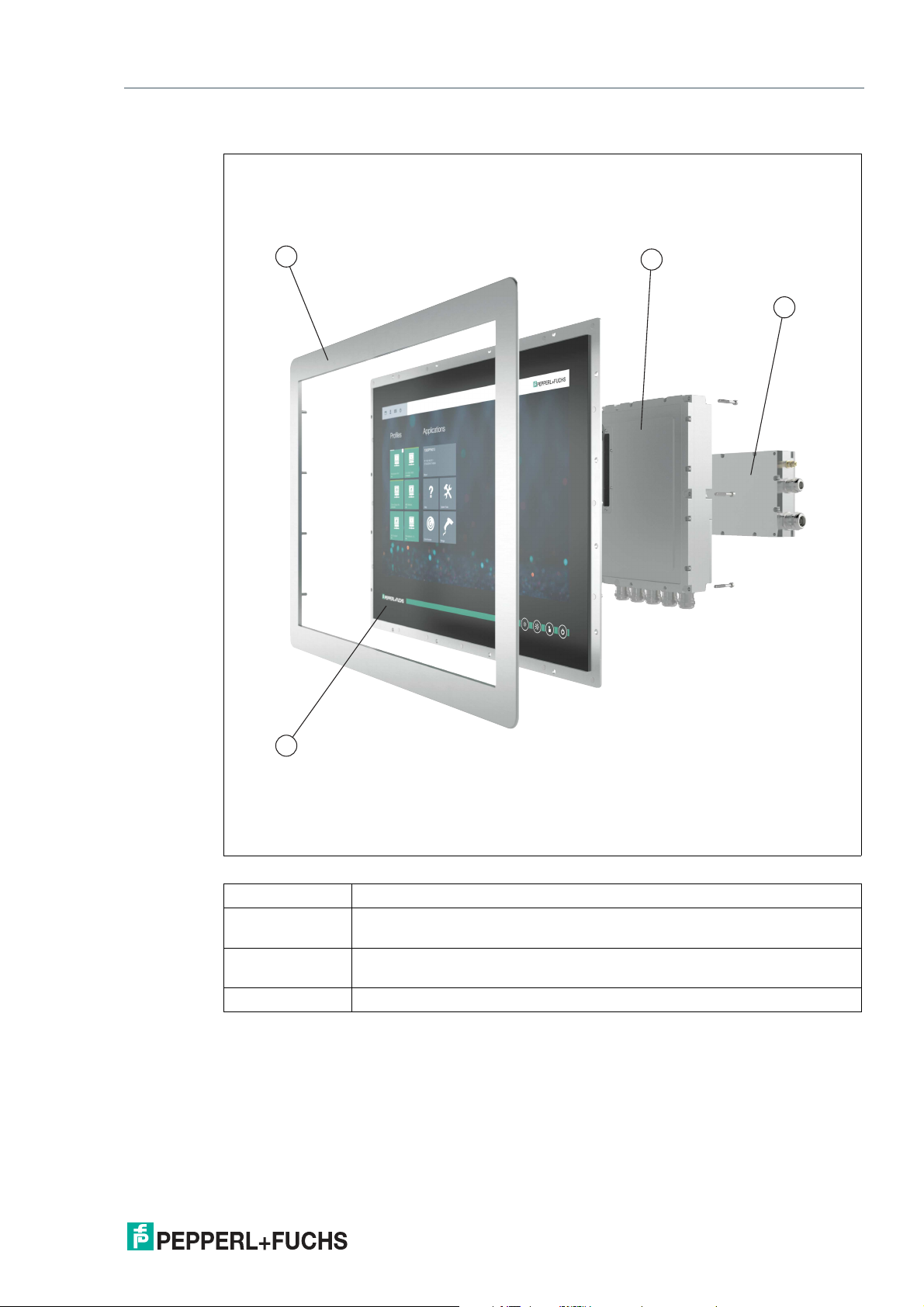
Product Description
VisuNet GXP Panel Components
Figure 2.1 VisuNet GXP panel components
1 Bezel for housing and panel mounting
2 Computing unit (TCU or PCU): processor, SSD and memory, Ex circuits,
interface modules
3 Power supply unit: DC or AC option, backpacked (panel-mount) or stand-
alone (in system enclosure)
4 Display unit: display, touch screen, hardened front glass
The VisuNet GXP system can also be ordered pre-mounted in an AG-XX00 housing, ready for
pedestal or wall mounting.
2020-09
7
Page 8
VisuNet GXP
Product Description
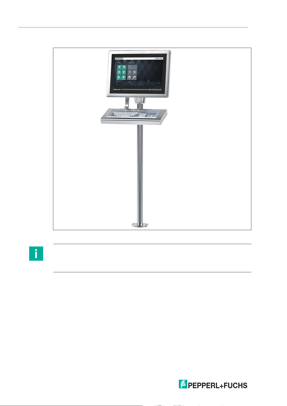
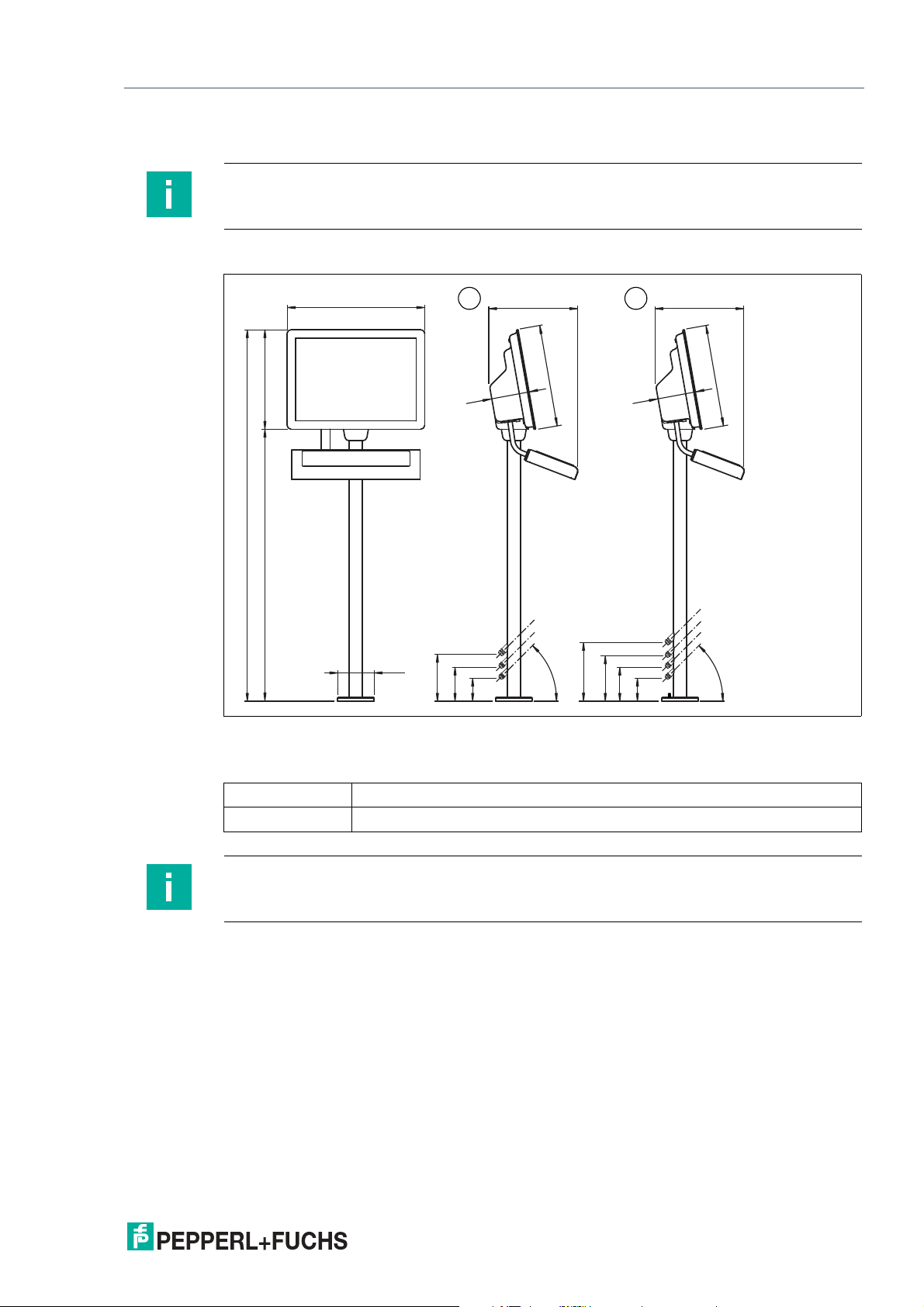
VisuNet GXP Pedestal Mounted with Keyboard/Mouse
Figure 2.2 VisuNet GXP workstation mounted in an AG-XX00 housing on a PEDESTAL-XX00-*
pedestal with optional EXTA2-* keyboard/mouse (ordered separately)
Note
For a description of the product model nomenclature, see the VisuNet GXP PC or VisuNet GXP
RM product datasheets at www.pepperl-fuchs.com.
For more mounting options and information, see the VisuNet Mounting Options datasheet.
2020-09
8
Page 9
VisuNet GXP
Product Description
2.2 Technical Specifications
Technical Data RM-GXP*
Hardware
Processor Intel® Atom™ Apollo Lake E3930
RAM 4 GB
Mass storage 32 GByte industrial grade MLC SSD
Software
Operating system VisuNet RM Shell 5.x (based on Microsoft®
Technical Data PC-GXP*
Hardware
Processor Intel® Atom™ Atom Apollo Lake E3940
RAM 8 GB
Mass storage 240 GByte industrial grade SSD
Windows 10 IoT Enterprise 2019 LTSC (x64))
Optional: 480 GByte SSD
Software
Operating system Microsoft® Windows 10 IoT Enterprise 2019
Technical Data RM-GXP* and PC-GXP*
Supply
Power consumption
AC 115/230 V AC, 0.4 ... 0.7 A, 50/60 Hz
DC 18 ... 36 V DC , 1.5 ... 3 A
Indicators/operating means
Display
Type Liquid Crystal Display (LCD) with LED back-
Screen diagonal 54.61 cm (21.5 inch)
Resolution 1920 x 1080 pixels (Full HD)
Color depth 24 bit (16.7 M) color
Contrast 5000:1 (typically)
Brightness
Reading angle 175° in all directions
Life span back lamp life: 50.000 hrs typical half life , at
Input devices
Touchscreen optional: projective capacitive; 10 finger multi-
Keyboard Foil keyboard with different pointing device
2020-09
LTSC (x64)
light
Aspect ratio 16:9
300 cd/m
25 °C (77 °F)
touch, glove friendly
options available (see EXTA2 datasheet)
2
9
Page 10
VisuNet GXP
Product Description
Interface
Interface type Standard:
1 x Ethernet 100/1000BASE-TX (Ex e) or
1 x fiber optic 1000BASE-SX (Multimode) or
1 x fiber optic 1000BASE-LX (Singlemode),
1 x USB 2.0 (Ex e),
2 x USB 1.1 (Ex i; intended for Pepperl+Fuchs
keyboard and mouse),
1 x DC or AC power in (via power supply unit)
Optional:
1 x barcode reader interface Pepperl+Fuchs
Pscan-D/B (Ex i)
"interface 3": 1 x barcode reader interface for
wired 1-D scanners IDM-160-D*, IDM-Z1160-D-* and base station IDMx61-B-* and
IDM-Z1-x61-B-* (Ex i)
"interface 4": 1 x barcode reader interface for
wired 2-D Scanner IDM-Z1-260-D-* (Ex i)
"interface 5": 1 x RS-232 interface with Power
Supply for miscellaneous devices and peripherals (Ex i)
1 x RS-485 (Ex e)
1 x Ethernet 100/1000Base-TX (Ex e) Bluetooth v4.0, communication distance up to 30
m in open terrain, transmission power +8
dBm, transmission frequency 2.402 ... 2.48
GHz
Directive conformity
Electromagnetic compatibility
Directive 2014/30/EU EN 61326-1:2013 (industrial locations)
Radio and telecommunication terminal equipment
Directive 2014/53/EU EN 301 328 V2.1.1
RoHS
Directive 2011/65/EU (RoHS) EN 50581:2012-09
non-Bluetooth products only
EN 301 489-1 V2.1.1
EN 301 489-17 V3.1.1
Bluetooth products only
10
Ambient conditions
Operating temperature -20 ... 50 °C (-4 ... 122 °F)
Display might react sluggishly below 0 °C
Storage temperature -20 ... 60 °C (-4 ... 140 °F)
Relative humidity 93% at 40°C, non-condensating, according to
EN60068-2-78
Altitude Operating altitude max. 2000 m
2020-09
Page 11
VisuNet GXP
Product Description
Ambient conditions
Shock resistance 18 shocks 15 g , 11 ms all axis, IEC 60068-2-
Vibration resistance 10 ... 150 Hz, +/- 0.075 mm , 1g, 10 cycles per
Mechanical specifications
Degree of protection IP66 (individual components and entire sys-
Material Internal:
Installation Flush-mount installation (requires customized
Mass Panel (DPU with bezel, TCU, PSU DC):
Dimensions Panel (DPU with bezel, TCU, PSU DC): 625
27
axis according to EN60068-2-6
tem with housing)
Panel: anodized aluminum (TCU, PCU, PSU),
powder coated aluminum (DPU)
External:
Bezel: stainless steel AISI 304 (1.4301)
System housing-H4: stainless steel AISI 304
(1.4301), bead blasted, typical surface roughness Ra = 1.6 µm
mounting kit)
Panel-mount installation into system housing
with bezel
Panel-mount installation into cabinet with
Bezel and standard mounting kit
approx. 23 kg\r Panel (DPU with bezel, TCU,
PSU AC): approx. 24 kg\r System housing
(AG-XX00): approx. 11 kg
mm x 459 mm x 120 mm
Panel (DPU with bezel, TCU, PSU AC): 625
mm x 459 mm x 137 mm
Panel with system housing: 625 mm x 459 mm
x 173 mm
Panel cut-out dimensions: 583 mm x 417 mm
(installation surface)
Data for application in connection with hazardous areas
EU-type examination certificate Zone 1/21: BVS 17 ATEX E 036 X
Directive conformity
Directive 2014/34/EU EN 60079-0:2012+A11:2013, EN 60079-
International approvals
UL approval E492874
IECEx approval IECEx BVS 17.0029X
Standards IEC 60079-0:2011, IEC 60079-5:2015, IEC
2020-09
Zone 2/22: BVS 17 ATEX E 037 X
5:2015, EN 60079-7:2015, EN 6007911:2012, EN 60079-31:2014
60079-7:2015, IEC 60079-11:2011, IEC
60079-31:2013
11
Page 12
VisuNet GXP
Product Description
Note
For more technical information, refer to the documentation for the individual components:
Marking
ATEX
RM-GXP1100-J1-*
PC-GXP1100-J1-*
RM-GXP1200-J2-*
PC-GXP1200-J2-*
• Display Units DPU1100-J1* and DPU1200-J2*
• AC Power Supply Units PSU1100-J1-AC-N0 and PSU1200-J2-AC-N0
• DC Power Supply Units PSU1100-J1-DC-N0 and PSU1200-J2-DC-N0
• Thin Client Units TCU1100-J1-* and TCU1200-J2-*
• Personal Computer Units PCU1100-* and PCU1200-*
• Peripherals such as keyboards or barcode readers
II 2G Ex eb q ib [ib] IIC T4 IP66 Gb
II 2D Ex tb [ib] IIIC T85°C IP66 Db
II 3G Ex ec [ib] q IIC T4 IP66 Gc
II 3D Ex tc [ib] IIIC T85 °C IP66 Dc
IECEx
RM-GXP1100-J1-*
PC-GXP1100-J1-*
RM-GXP1200-J2-*
PC-GXP1200-J2-*
UL
Ex eb q ib [ib] IIC T4 IP66 Gb
Ex tb [ib] IIIC T85°C IP66 Db
Ex ec [ib] q IIC T4 IP66 Gc
Ex tc [ib] IIIC T85 °C IP66 Dc
12
2020-09
Page 13
VisuNet GXP
625
451
(1687)
~ 400
173
1236
ø 165
104
154
214
45°
~ 400
104
154
204
45°
1 2
263
459
173
459
Product Description
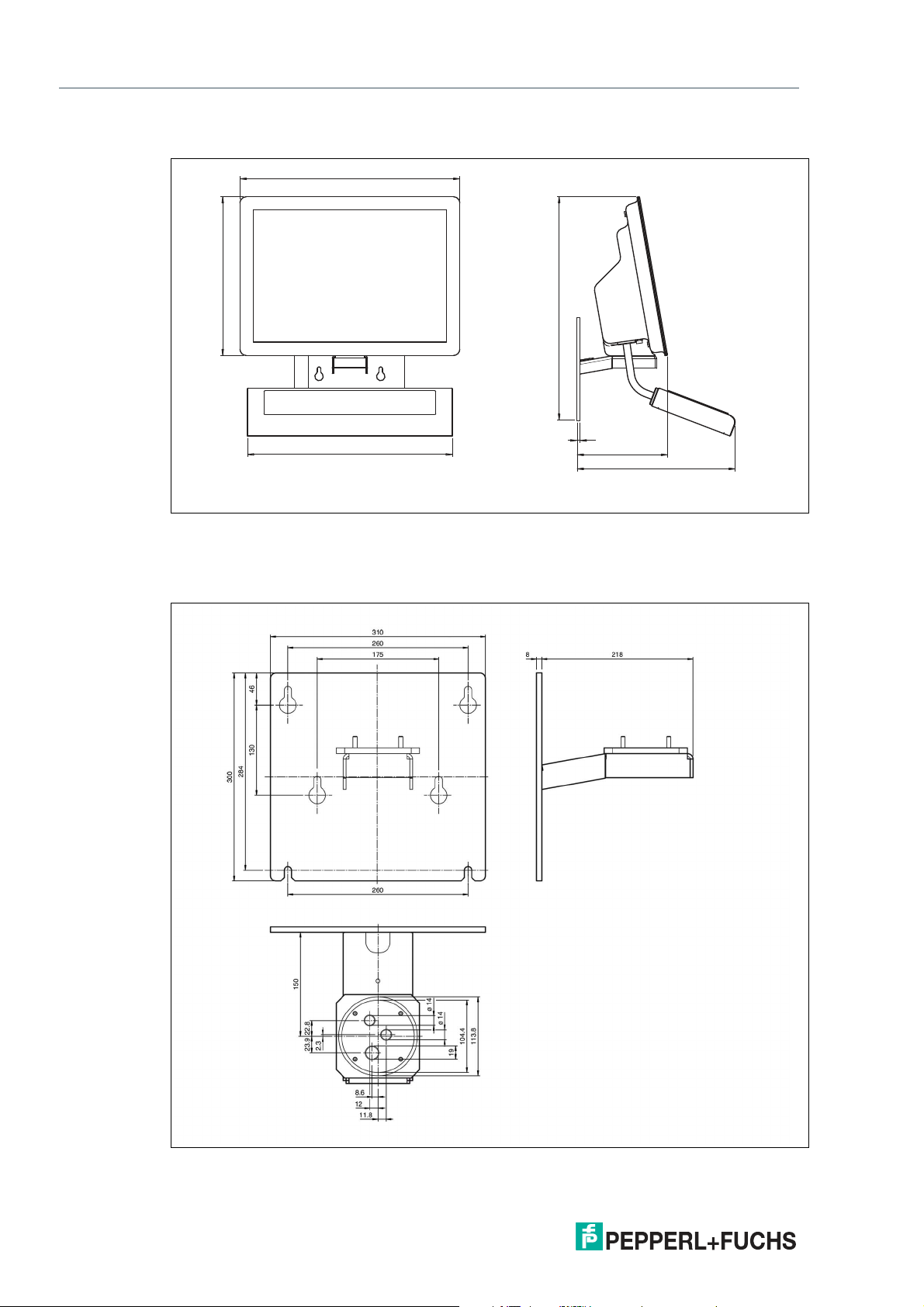
2.3 Dimensions
Note
For more options and information, refer to the VisuNet GXP Mounting Options datasheet.
Pedestal Mount
VisuNet GXP system H1 housing installed into AG-XX00 housing with additional PEDESATALXX00-* pedestals and EXTA2-* keyboard inside an -F housing with -G mounting version (1-Arm
for mounting to AG-XX00 housing)
1 Shown with PEDESTAL-XX00-124-3-304-TRN-N0
2 Shown with PEDESTAL-XX00-124-4-304-TRN-N0
Note
2020-09
EXTA2-* keyboard and PEDESTAL-XX00-* pedestals must be ordered separately.
13
Page 14
VisuNet GXP
256
450
635
582
8
625
451
Product Description
Wall Mount
Figure 2.3 VisuNet GXP system H1 housing installed into AG-XX00 housing with additional WALL-
BRACKET-XX00-3-304-N0 and EXTA2 keyboard inside an -F housing with -G mounting
version (1-Arm for mounting to AG-XX00 housing)
Wall Mount Hole Pattern
Figure 2.4
2020-09
14
Page 15
VisuNet GXP
23.5
633
584
418
467
17.3 114
Product Description
Panel Mount
Figure 2.5 VisuNet GXP system S1 housing including bezel, prepared for panel mounting, with KIT-
PM-XX00-22F-304-N0 kit for panel mounting
2020-09
15
Page 16
VisuNet GXP
Mechanical Installation
3 Mechanical Installation
3.1 Unpacking
Warning!
Risk of injury
Handling the VisuNet GXP components without gloves may cut fingers, hands, or wrists.
Wear gloves at all times during installation.
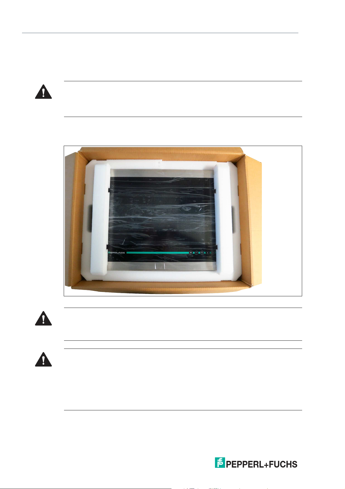
The VisuNet GXP comes with its core components preassembled. These components consist
of a display unit (DPU), power supply unit (PSU), and thin client unit (TCU) or PC unit (PCU). If
the housing option is chosen, the components come pre-mounted into the housing.
16
Figure 3.1 VisuNet GXP in the box
Caution!
Scratches and damage
GXP components may become scratched or damaged if they are placed onto or slid across
hard surfaces.
Warning!
Danger resulting from scratched DPU screen
Scratches in the DPU screen weaken the glass structure. This may result in glass breakage in
the event of an explosion. Explosion protection is no longer ensured if a DPU with a scratched
screen is used.
NEVER use a DPU with a scratched screen in a hazardous area. If the surface is damaged in
any way, return the DPU to Pepperl+Fuchs at once and replace it with a new one. See chapter
3.3.13 for information about removing the DPU.
2020-09
Page 17
VisuNet GXP
Mechanical Installation
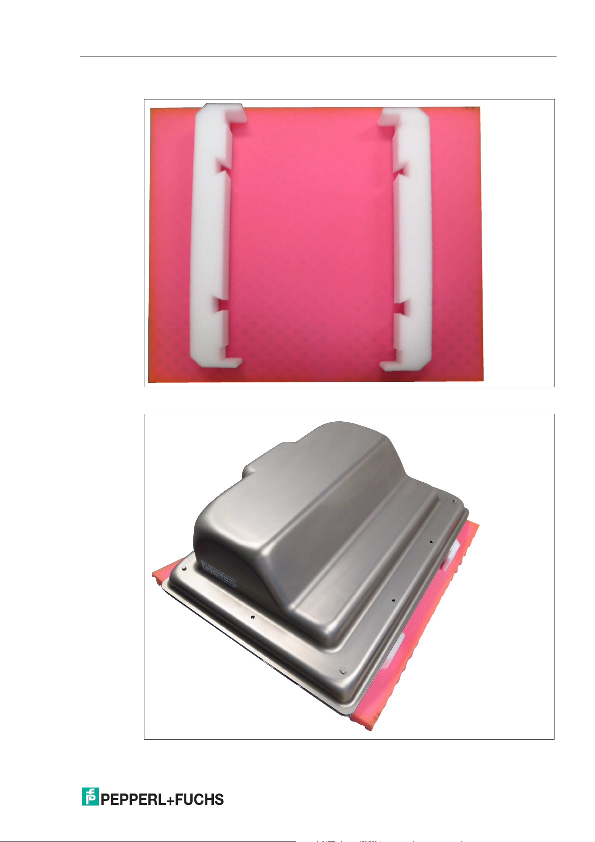
Using Foam Brackets During Installation
Figure 3.2 To help protect the VisuNet GXP components once they have been removed from the box,
use the enclosed foam brackets.
Figure 3.3 To protect the DPU front screen, place the VisuNet GXP face down onto the foam brackets.
2020-09
17
Page 18
VisuNet GXP
Mechanical Installation
3.2 Electrical Installation
Warning!
Danger of Explosion
Cable insulation may become damaged if cables and connection lines are not used in adequate temperature ranges. Thus, short circuits within the cable may occur which in turn may
give rise to sparks and/or surface temperatures capable of triggering an ignition.
Only use cables and connection lines which are suitable to be used within a temperature rating
of 80 °C if the system components are used within an ambient operating temperature of Ta > 40
°C.
Note
Refer to the manuals of the individual VisuNet GXP components for more information on
electrical installation and wiring.
Danger!
Explosion hazard from wrong or missing grounding
Wrong or missing grounding can cause sparks. This can ignite the surrounding potentially
explosive atmosphere.
• Ground the device. Observe the grounding requirements.
• Ensure that external ground connections exist, are in good condition, and are not dam-
aged or corroded.
Warning!
Risk of electric shock or property damage from inadequate grounding
If you do not ground the device correctly, this could result in potential equalization currents.
These currents could hurt operating personnel or cause property damage.
Ground the device via the grounding bolt. Ensure that a correct potential equalization is guaranteed at all times.
When installing the VisuNet GXP system, always ensure a proper grounding of all components,
including housing and mounting parts (e.g., pedestal and wall bracket) with a cable diameter of
at least 4 mm2in accordance with IEC 60079-14.
The VisuNet GXP is shipped with the following protective earth (PE) wiring connections, if the
AG-XX00 housing option is selected:
• PE wire from the DPU PE stud to the AG-XX00 housing PE stud.
• PE wire from the PSU PE stud to the AG-XX00 housing PE stud.
18
2020-09
Page 19
VisuNet GXP
Mechanical Installation
3.3 System Installation
3.3.1 General Installation Information
Observe the following requirements when installing the system components.
• The equipment must be installed by competent personnel in accordance with the instruc-
tions. National laws and regulations must be observed.
• The building installation must provide a 20 A overcurrent protection.
• The installer must make a readily accessible disconnect device available.
• The safety of any system incorporating the PSU is the responsibility of the assembler of
the system.
Included with Delivery
• Pre-assembled VisuNet PC- or RM-GXP panel (pre-mounted into AG-XX00 housing
when "H1" option is selected)
• 2 x protective tubes
• 1 x Ferrite ring with 1 x Ferrite key
• Screws for housing
Items Ordered Separately
• Pedestal that is compatible with AG-XX00 housing (StandardLine or BasicLine pedestal)
• Optional EXTA2-* keyboard
Warning!
Risk of injury
Lifting the device on your own may lead to injury.
Do not attempt to lift the device on your own. Use a crane or have another person help you.
Warning!
Proper installation on the floor
It is the installer's responsibility to select a suitable location with sufficient strength to hold the
equipment. It is the installer's responsibility to select the proper screws based on the installation conditions.
2020-09
19
Page 20
VisuNet GXP
104
154
214
45°
104
154
204
45°
1 2
263
Mechanical Installation
3.3.2 Preparing for Pedestal Installation
For floor mounting, the preferred installation option uses PEDESTAL-XX00-* with either 3 or 4
cable glands. The pedestal is shipped with a pre-installed rotating coupling with four bolts and
a PE wire, which is attached to the pedestal tube.
Figure 3.4 Pedestal with optional 3 or 4 cable glands
1 PEDESTAL-XX00-124-3-304-TRN-N0 with 3 cable glands
2 PEDESTAL-XX00-124-4-304-TRN-N0 with 4 cable glands
20
2020-09
Page 21
VisuNet GXP
Mechanical Installation
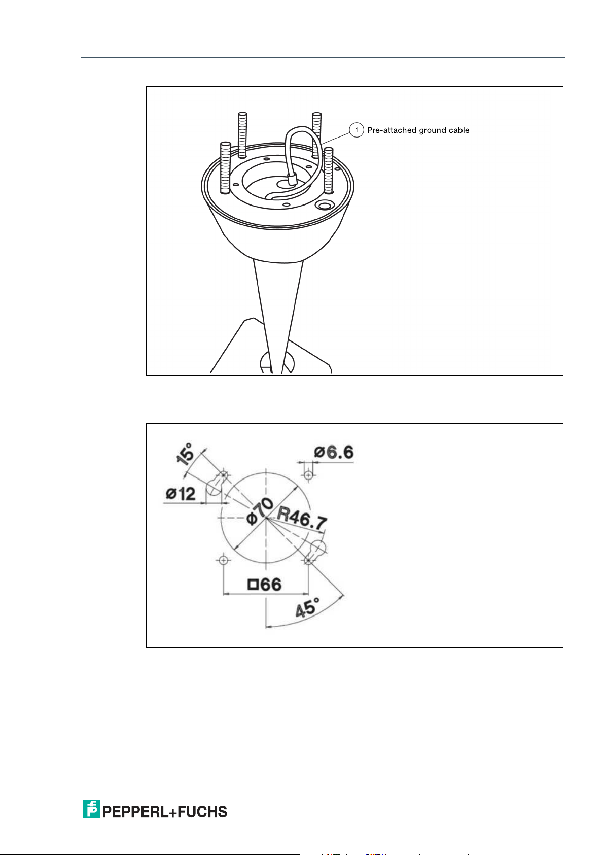
Figure 3.5 Pedestal with PE wire
1 PE wire
Figure 3.6 Pedestal adapter hole pattern
2020-09
21
Page 22

VisuNet GXP
Mechanical Installation
Preparing the Pedestal for Connection to the Housing
1.
Align the pedestal so that the cable glands point away from you.
2.
The pedestal must be firmly screwed to the floor.
3.
Bend the PE wire with a max. radius of 20 mm and place it within the pedestal tube.
4.
Place the O-ring and sealant into the channel of the coupling.
Adjusting the Rotation of the Coupling
1.
Loosen the worm screws in the inner ring with a hexagon socket wrench.
2.
Use an appropriate tool to open the locking ring.
22
3.
Adjust the ease of rotation for your application.
4.
Tighten the worm screws in the inner ring with a hexagon socket wrench.
2020-09
Page 23

VisuNet GXP
Mechanical Installation
3.3.3 Mounting the Housing onto the Pedestal
Warning!
Risk of injury
Lifting the device on your own may lead to injury.
Do not attempt to lift the device on your own. Use a crane or get another person to help you.
Warning!
Risk of injury
While the device is resting on the pedestal and the nuts have not yet been fixed to the screws,
the device may tip over and fall off the pedestal, become damaged, and cause injury.
Make sure to prevent the housing from tipping over by securing it manually (e.g., holding on
to it) until the nuts have been firmly attached to the screws and the housing is securely attached
to the pedestal.
Required Components
• Prepared pedestal that is properly secured to the floor
• VisuNet GXP pre-assembled in an AG-XX00 housing
Required Installation Tools
• 8 mm socket wrench for attaching PE hardware and housing screws
• 10 mm flat wrench for nuts on pedestal set screws
• Open-ended wrench for cable glands (cable gland installation tool)
• Safety gloves
• Loctite® Threadlocker Blue 243®
2020-09
23
Page 24

VisuNet GXP
Mechanical Installation
Attaching Housing to Pedestal
1.
Align the pedestal bolts to the hole pattern on the bottom of the housing by rotating the pedestal
coupling 90° in relation to the cable glands at the bottom of the pedestal.
2.
Carefully place the housing face down on an even, cushioned surface.
3.
Remove all screws from the back of the housing.
4.
Carefully turn the housing so that the display is facing up.
5.
Using a crane or with the help of another person, place the housing onto the pedestal so
that the pedestal bolts align with the keyhole slots and the housing rests on the pedestal.
Manually secure the housing the entire time so that the DPU does not fall open.
24
Warning!
Damage to the PE wire
The PE wire may become damaged if it gets stuck between the pedestal and
the housing.
Bend the PE wire in such a way that it does not get stuck between the pedestal
and the housing.
6.
While manually securing the housing (e.g., by holding on to it), open the housing.
2020-09
Page 25

VisuNet GXP
Mechanical Installation
Opening the AG-XX00 Housing
Figure 3.7
2020-09
25
Page 26
VisuNet GXP
Mechanical Installation
26
Figure 3.8
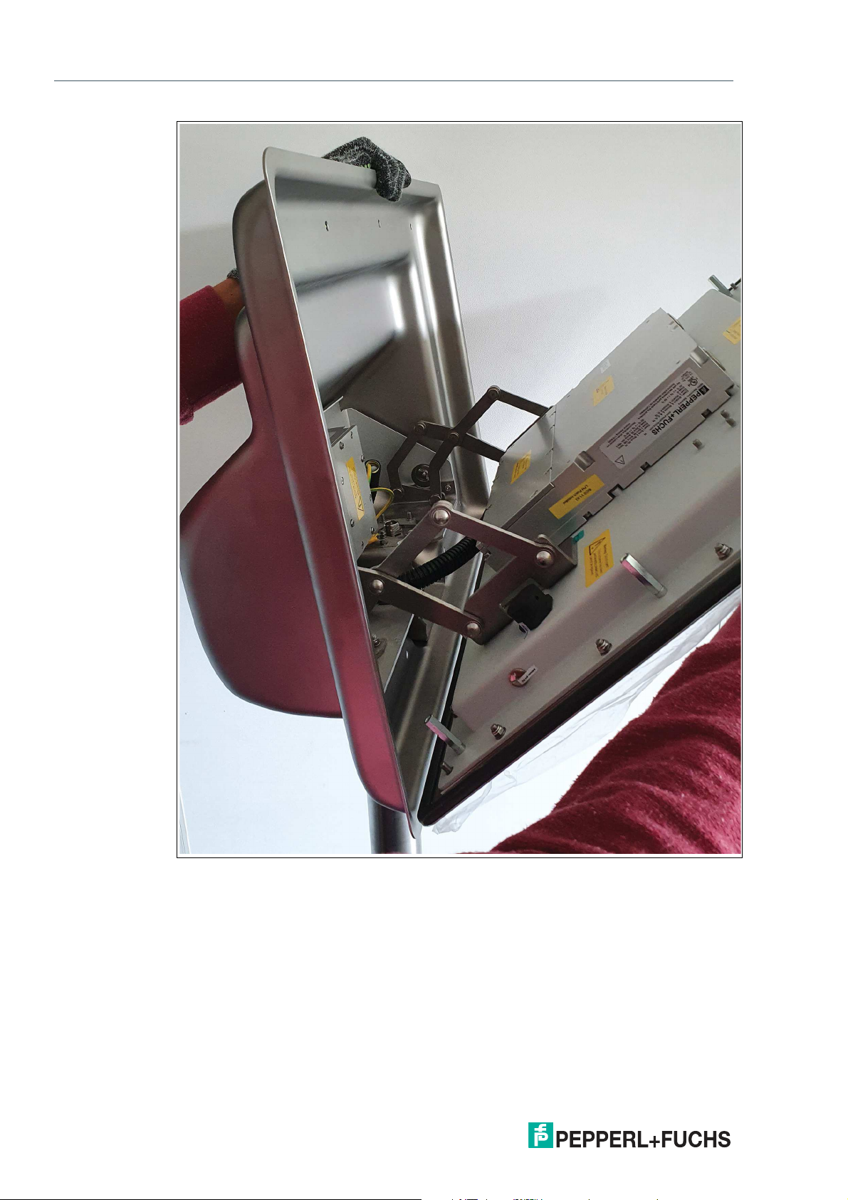
7.
Slowly lower the DPU until the hinges engange.
8.
While continuing to manually secure the housing (e.g. by holding on to it), tip the display
panel toward you until the display comes to rest at its fully opened position and the hinges are
stretched out.
2020-09
Page 27

VisuNet GXP
Mechanical Installation
Figure 3.9
2020-09
27
Page 28

VisuNet GXP
Mechanical Installation
9.
Tigthen the M6 U-washers onto the pedestal bolts using a torque of 7.5 Nm.
Note
Optional: Secure the nuts with a medium-strength bolt adhesive such as Loctite® Threadlocker
Blue 243®
28
2020-09
Page 29

VisuNet GXP
1
2
3
4
Mechanical Installation
3.3.4 Installing Cables in the Pedestal
Warning!
Pinched cables
Ensure that cables do not get pinched or damaged during installation.
Note
Refer to the manuals of the individual components for information on electrical installation and
wiring.
Required Installation Tools
• Cable gland installation tool
• Small cable ties
• Side cutters
All tools should be torque controlled if a torque is specified.
Cable Gland and Opening Overview
Pedestal with Four Cable Glands
1 M20
2 M16
3 M16
4 M16
2020-09
29
Page 30

VisuNet GXP
1
2
3
Mechanical Installation
Pedestal with Three Cable Glands
1 M20
2 M16
3 M16
Opening/Wrench Size, Cable Diameter, and Torque
Opening Size Wrench Size Cable Diameter Torque
M20 24 mm 7 ... 12 mm 10 Nm
M16 20 mm 3 ...7 mm 5 Nm
M16 20 mm 6 ... 10 mm 5 Nm
2020-09
30
Page 31

VisuNet GXP
Mechanical Installation
Installing Cables
1.
Based on how many cables and openings are required (i.e., power and Ethernet), remove the
appropriate number of cable glands at the bottom of the pedestal.
2.
Put the gland nut and ferrule of the cable gland on the cable and slide them a few meters down
the length of the cable away from the pedestal. Keep the nut and ferrule on the cable. They will
be tightened in a later installation step.
3.
Route the cables through the cable glands, up through the pedestal tube, and out through the
top of the pedestal.
2020-09
31
Page 32

VisuNet GXP
Mechanical Installation
4.
Pull the cable through the pedestal so that 50 cm of the cable is hanging out of the top of the
pedestal.
5.
Repeat the preceding steps for each cable that must be routed through the pedestal.
The pedestal is now ready for connection.
32
2020-09
Page 33

VisuNet GXP
Mechanical Installation
3.3.5 Grounding the Housing to the Pedestal
When installing the VisuNet GXP system, always ensure that all components are properly
grounded, including housing and mounting parts (e.g., pedestal and wall bracket) with a cable
diameter of at least 4 mm2 in accordance with IEC 60079-14.
When the AG-XX00 housing option is selected, the VisuNet GXP is shipped with the following
PE connections:
• PE wire from the DPU PE stud to the AG-XX00 housing PE stud
• PE wire from the PSU PE stud to the AG-XX00 housing PE stud
If you replace the DPU or PSU, reestablish the PE connection in the same configuration.
Tighten the PE hardware to 4.0 Nm.
Figure 3.10 Factory-assembled ground connections to the housing
Warning!
Connection to the PE studs
Connection to the PE studs is mandatory.
Warning!
Operator responsibility to verify grounding path
Check the grounding path after completing system installation.
Warning!
Risk of personal injury and equipment damage
Pinched PE wire
Ensure that the PE wire does not become pinched between the pedestal and housing.
2020-09
33
Page 34

VisuNet GXP
Mechanical Installation
Danger!
Explosion hazard from wrong or missing grounding
Wrong or missing grounding can cause sparks. This can ignite the surrounding potentially
explosive atmosphere.
• Ground the device. Observe the grounding requirements.
• Ensure that external ground connections exist, are in good condition, and are not dam-
Warning!
Risk of electric shock or property damage from inadequate grounding.
If you do not ground the device correctly, this could result in potential equalization currents.
These currents could hurt operating personnel or cause property damage.
Ground the device via the grounding bolt. Optionally, ground the device additionally via the terminal X1.1. When both are used, ensure that a correct potential equalization is guaranteed at
all times.
aged or corroded.
Note
Refer to the manuals of the individual components for more information on electrical installation
and wiring.
Grounding the AG-XX00 Housing to PEDESTAL-XX00-*.
1.
Connect the pre-installed PE wire on the pedestal to the PE stud on the AG-XX00 housing.
2.
Ground the pedestal with the PE stud on the bottom plate of PEDESTAL-XX00-*.
3.
Fasten the hardware with a torque of 4.0 Nm.
34
Figure 3.11
2020-09
Page 35

VisuNet GXP
Mechanical Installation
Grounding Concept
Figure 3.12
Note
For more information on installing the input power and output power cables, refer to the VisuNet
GXP PSU manuals.
2020-09
35
Page 36

VisuNet GXP
Mechanical Installation
3.3.6 Installation of the Ferrite Ring
In order to meet certain electrical noise emission limits and to protect the VisuNet GXP from
external influences, it is necessary to install a ferrite core on the Power Supply cable connected
to the PSU. There is one ferrite core included with the VisuNet GXP System or Panel Mount. To
install the ferrit, simply route the cable through the center of the core and then take one wrap
around the outside of the core and route the cable through again, in total there must be 2 turns.
This should be done as close to the enclosure as possible.
36
Figure 3.13
2020-09
Page 37

VisuNet GXP
256
450
635
582
8
625
451
Mechanical Installation
3.3.7 Wall Mount Installation
Warning!
Proper installation on the wall
It is the installer's responsibility to select a suitable location with sufficient strength to hold the
equipment. It is the installer's responsibility to select the proper screws based on the installation conditions.
Figure 3.14 VisuNet GXP system H1 housing installed into AG-XX00 housing with additional WALL-
BRACKET-XX00-3-304-N0 and EXTA2 keyboard inside an -F housing with -G mounting
version (1-Arm for mounting to AG-XX00 housing)
Required Components
• Pre-assembled VisuNet PC- or RM-GXP panel mounted into AG-XX00-* housing (-H1
housing)
• Wall bracket adapter for wall mounting installation compatible with AG-XX00-* housing
• Optional EXTA2-* keyboard/mouse
Required Installation Tools
• 8 mm socket wrench for attaching PE hardware and housing screws
• Safety gloves
• Loctite® Threadlocker Blue 243®
2020-09
37
Page 38

VisuNet GXP
Mechanical Installation
Wall Mounting
1.
See the VisuNet GXP Mounting Options datasheet for the hole pattern.
2.
Install the bracket to the wall.
3.
Connect the PE wire from the field to the PE stud on the wall bracket.
4.
Mount the VisuNet GXP to the bolts on the wall bracket. Follow the relevant steps required for
mounting the housing to a pedestal. See chapter 3.3.3
5.
With the DPU hinged down, route cables through the cable glands in the wall bracket.
• A cable tie socket could be used to attach the cables.
• Cables can be routed from the top through the cutout in the wall bracket or from the bot-
tom.
Note
Always consider the allowed bending radii. See the VisuNet GXP TCU/PCU
manual for information about wiring the TCU/PCU.
6.
Close the housing. See chapter 3.3.12
Figure 3.15 Bottom view of wall bracket
1. PE stud
Note
Grounding the AG-XX00 Housing to the Wall Bracket
The AG-XX00 housing is grounded indirectly via the wall bracket. It does not require an
additional PE wire between housing and wall bracket.
38
2020-09
Page 39

VisuNet GXP
Mechanical Installation
3.3.8 Mounting the Keyboard
The EXTA2-* is the system keyboard/mouse available with a mounting option for the VisuNet
GXP AG-XX00 housing.
Required Components
• VisuNet GXP pre-assembled in AG-XX00 housing
• EXTA2-* keyboard/mouse (screws included)
Required Installation Tools
• 3 mm hex wrench for cover screws
• 4 mm hex wrench for keyboard arm
• Loctite® Threadlocker Blue 243®
All tools should be torque controlled if a torque is specified.
Mounting the EXTA2-*-G-* Keyboard to Housing AG-XX00
1.
Open and remove the four cover plate screws on the bottom-left side of the AG-XX00 housing.
2.
Route the keyboard cable with the protective tube through the hole of the AG-XX00 housing.
3.
Using the screws and lock washers delivered with the EXTA2-*-G-* keyboard, attach the
keyboard to the AG-XX00 housing.
2020-09
39
Page 40

VisuNet GXP
Mechanical Installation
4.
Fasten the four screws with a torque of 6 Nm.
Note
Secure the screws with a medium-strength bolt adhesive, such as Loctite® Threadlocker Blue
243®.
Refer to the TCU/PCU manual for more information on installation and connection.
40
2020-09
Page 41

VisuNet GXP
Mechanical Installation
3.3.9 Mounting the IDM-* Barcode Reader Holder Bracket
SCANNER-HOLDER-U1-XX00-N0 is a holder for the IDM-* handheld barcode reader family.
The holder is compatible with the VisuNet GXP AG-XX00 housing.
Required Components
• VisuNet GXP pre-assembled in AG-XX00 housing
• SCANNER-HOLDER-U1-XX00-N0 (screws included)
Required Installation Tools
• Size 8 socket wrench for housing screws
• 3 mm hex wrench for scanner holder screws
All tools should be torque controlled if a torque is specified.
Figure 3.16 SCANNER-HOLDER-U1-XX00-N0 (screws and adapter included)
2020-09
41
Page 42

VisuNet GXP
Mechanical Installation
Mounting SCANNER-HOLDER-U1-XX00-N0 to AG-XX00 Housing
1.
Open the housing. See chapter 3.3.3
Figure 3.17
2.
Remove the cover plate on the outside right side of the AG-XX00 housing by opening the wing
screw that is located on the inside of the housing.
42
2020-09
Page 43

VisuNet GXP
Mechanical Installation
3.
Connect the adapter (included with the scanner holder in delivery) to the scanner holder with
the enclosed screws.
4.
From the inside-right of the AG-XX00 housing, use a hex key to put the first screw (with lock
washer and sealing washer) through one of the drilled holes on the adapter.
5.
Press the adapter and scanner holder against the housing from the outside and fasten the
screw using a torque of 6 Nm.
6.
From the inside of the AG-XX00 housing, use the hex key to put the second screw (with lock
washer and sealing washer) through the other drilled hole on the adapter. Fasten the screw
using a torque of 6 Nm.
The scanner holder is now attached to the housing.
2020-09
43
Page 44

VisuNet GXP
Mechanical Installation
44
Figure 3.18 Dimensions with scanner holder
Follow the same steps to mount HOLDER-BRACKET-XX00-IDMx61-B-N (#548396). This
bracket holds the IDM base station.
2020-09
Page 45

VisuNet GXP
Mechanical Installation
Figure 3.19 HOLDER-BRACKET-XX00-IDMx61-B-N (screws and adapter included)
2020-09
45
Page 46

VisuNet GXP
Mechanical Installation
46
Figure 3.20
2020-09
Page 47

VisuNet GXP
Mechanical Installation
3.3.10 Cable Installation for IDM-* Readers and Base Stations
DATL-IDM-DB-S-XX00-N0 and CBL-IDMx60-D-* are used to install IDM-Z1-160-D-1D-J1-*,
IDM-160-D-1D-*, IDM-Z1-260-D-2D-J1-S1-N-N0, or IDM-Z1-x61-B-J1-BT-N0 and IDM-x61-*
to the VisuNet GXP RM/PC. The cables are compatible with the VisuNet GXP AG-XX00 housing.
Required Components
• S3 or S4 Interface (thin client / PC-unit)
• DATL-IDM-DB-S-XX00-N0
• CBL-IDMx60-D-J1-S-S18-N0 or CBL-IDMx60-D-J1-S-C38-N0
• IDM-Z1-160-D-1D-J1-*, IDM-160-D-1D-*, IDM-Z1-260-D-2D-J1-S1-N-N0, or IDM-Z1-
x61-B-J1-BT-N0 and IDM-x61-* in combination with required Bluetooth handheld barcode
reader
• Optional Scanner Holder or Holder Brackets
Required Installation Tools
• Flat head screwdriver
• 19 mm socket wrench for counter nut and connector
• Size 2.5 hex wrench for cable tie screws
• Safety gloves
All tools should be torque controlled if a torque is specified.
Cable DATL-IDM-DB-S-XX00-N0
Connector cable for wired 1-D scanner IDM-Z1-160-D-1D-J1-S-*, IDM-160-D-1D-* (S3-Interface required) and 2-D scanner IDM-Z1-260-D-2D-J1-S* (S4-Interface required) 4-wire with
ferrules - IDM scanner connection via M12 connector.
Note
Supports only RS-232 scanner / base station
2020-09
47
Page 48

VisuNet GXP
Mechanical Installation
Installing the Cable DATL-IDM-DB-S-XX00-N0
1.
Open the housing. See chapter 3.3.3
2.
Remove the plug at the bottom-right side of the housing by holding the screw steady from
below with a screwdriver while loosening the screw from above with a wrench.
3.
Guide the open wire end of the cable DATL-IDM-DB-S-XX00-N0 through the hole.
4.
Place the M16 counter nut over the end of the cable.
48
2020-09
Page 49

VisuNet GXP
Mechanical Installation
5.
Pull the socket into the housing and tighten it with the M16 counter nut. Tighten the nut with a
torque of 5 Nm.
6.
Protect the cable from mechanical damage by fastening it with a cable tie.
7.
Route the cable through the cable gland on the TCU/PCU. Install the wire ends per the tables
below.
Wiring Guide
DATL-IDM-DB-S-XX00-N0 to IDM-Z1-160* and Base Station IDM-Z1-x61-B-N0* Ex i
TCU Cable
Terminal Signal
Name Direction Assignment Color coding Pin M12 con-
Xx.1 Vcc Supply Vcc green 1
Xx.2 GND Supply GND brown 3
Xx.3 - - - - -
Xx.4 - - - - -
Xx.5 - - - - -
Xx.6 RxD I TxD white 4
Xx.7 - - - - -
Xx.8 - - - - -
nector
2020-09
49
Page 50

VisuNet GXP
Mechanical Installation
DATL-IDM-DB-S-XX00-N0 to IDM-Z1-260*
TCU Cable
Terminal Signal
Xx.1 Us Supply Vcc green 1
Xx.2 RxD I TxD white 4
Xx.3 - - - - -
Xx.4 - - - - -
Xx.5 GND Supply GND brown 3
Xx.6 - - - - -
Xx.7 - - - - -
Xx.8 - - - - -
Note
For detailed information on electrical installation, refer to the TCU/PCU and IDM* barcode
reader manuals.
Name Direction Assignment Color coding Pin M12 con-
nector
Connecting the IDM-* Barcode Reader
Connect the plug of the barcode reader to the socket and tighten it firmly.
Coded Plug and Socket
Figure 3.21 The plug and socket are coded. Match the coding on the plug and socket before tightening.
3.3.11 Cable Installation for PSCAN-D-* Handheld Readers
The DATL-PSCAN-D-XX00-N0 cable is used to install PSCAN-D-* handheld barcode readers
to the VisuNet GXP RM/PC. The cable is compatible with the VisuNet GXP AG-XX00 housing.
50
Required Components
• DATL-PSCAN-D-XX00-N0 cable
Required Installation Tools
• Flat head screwdriver
• 19 mm socket wrench for counter nut and connector
• Cable tie
All tools should be torque controlled if a torque is specified.
2020-09
Page 51

VisuNet GXP
Mechanical Installation
Installing DATL-PSCAN-D-XX00-N0
1.
Open the housing. See chapter 3.3.3
2.
Remove the plug at the bottom-right side of the housing by holding the screw steady from
below with a screwdriver while loosening the screw from above with a wrench.
3.
Guide the open wire end of the cable through the hole.
4.
Place the M16 counter nut over the end of the cable.
2020-09
51
Page 52

VisuNet GXP
Mechanical Installation
5.
Pull the socket into the housing and tighten it with the M16 counter nut. Tighten the nut with a
torque of 5 Nm.
6.
Protect the cable from mechanical damage by fastening it with a cable tie.
7.
Route the cable through the cable gland on the TCU/PCU. Install the wire ends per the table
below.
Wiring Guide
PSCAN-D* Handheld Reader Ex i
TCU Cable
Terminal Signal Assignment Color coding
Name Direction
Xx.1 Us Supply Us yellow 4
Xx.2 GND Supply GND brown/gray 1/5
Xx.3 - - - - -
Xx.4 TxD O RxD green 3
Xx.5 - - - - -
Xx.6 RxD I TxD white 2
Xx.7 - - - - -
Xx.8 - - - - -
Pin M12 connector
52
Note
For detailed information on electrical installation, refer to the TCU/PCU and PSCAN-D-*
barcode reader manuals.
2020-09
Page 53

VisuNet GXP
Mechanical Installation
Connecting the PSCAN-D-* Barcode Reader
Connect the plug of the barcode reader to the socket and tighten it firmly.
Coded Plug and Socket
Figure 3.22 The plug and socket are coded. Match the coding on the plug and socket before tightening.
3.3.12 Closing the Housing
Warning!
Risk of injury
Fingers can be inured when the display is moved backed into the housing.
Wear protective gloves and hold the display panel by the frame when moving it.
Warning!
Risk of cable damage
The cables may become damaged during the closing process.
Properly fasten all cables, place them in a protective tube, and push the tube into the pedestal
before closing the housing.
2020-09
53
Page 54

VisuNet GXP
Mechanical Installation
Closing the AG-XX00 Housing
1.
Slowly lift the DPU into an upright position until the bolts touch the inner frame of the housing.
54
Figure 3.23
2020-09
Page 55

VisuNet GXP
Mechanical Installation
Figure 3.24 Display panel bolts lined up with the cutout holes of the housing.
2020-09
55
Page 56

VisuNet GXP
Mechanical Installation
2.
Press the DPU and housing together at the top end of the system. From the back of the
housing, place one screw in the hole at the upper-left corner and one screw in the hole at the
upper-right corner of the housing.
Figure 3.25
56
Figure 3.26
3.
Tighten the two screws with a torque of 6 Nm.
4.
Repeat the previous step with all other screws, following a diagonal pattern.
2020-09
Page 57

VisuNet GXP
Mechanical Installation
3.3.13 Dismounting the Display Unit
If repairs are required, the DPU can be dismounted from the TCU/PCU and be replaced. Nuts
for fixing the hinges are included either with the VisuNet GXP System or with the housing AGxx
as replacement part.
Warning!
Danger of Explosion
An ignition may be triggered if the TCU/PCU is still energized when its terminal compartment is
opened.
Turn off the TCU/PCU and wait 3 minutes after de-energizing before opening the terminal compartment.
Dismounting the DPU
1.
Open the AG-XX00 housing (1). See chapter 3.3.3. After de-energizing (see above), open the
terminal compartment of the TCU/PCU. Remove all 10 screws from the back of the TCU/PCU
and take it off of the DPU (2).
Figure 3.27
2020-09
57
Page 58

VisuNet GXP
Mechanical Installation
2.
Remove the PE wire from the PE stud on the back of the DPU.
Figure 3.28
3.
To simplify replacement of the DPU, temporarily hold the TCU/PCU in place using cable ties.
Put cable ties through both mounting holes at the top-left and top-right corners, and hang the
TCU/PCU from the top of the housing frame.
1
1 Cable ties
4.
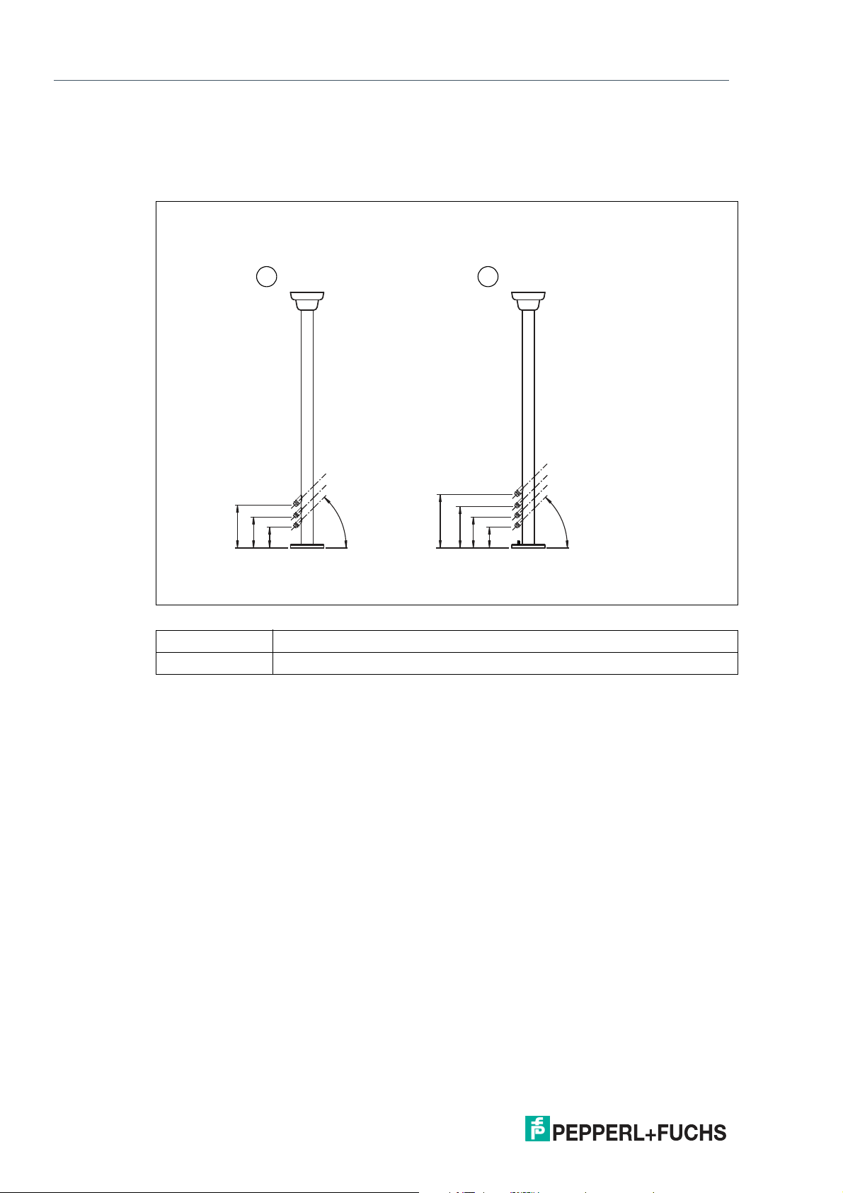
4. Read off the two vertical and the two horizontal installation values from the four scales and
note these down. These are the basis values for the installation of the new DPU.
Note
Due to tolerances the values do not have to be identical neither the horizontal
values nor the vertical values.
1. Use a torque of 4 Nm for tightening the PE hardware during the DPU reassembly process when these steps are performed in reverse
order.
58
2020-09
Page 59

VisuNet GXP
Mechanical Installation
Figure 3.29
Figure 3.30
2020-09
59
Page 60

VisuNet GXP
Mechanical Installation
5.
Now the DPU can be removed from the housing. During the removal process, hold the DPU
steady so it cannot fall down, preferably with the help of another person. Place the DPU on an
even, cushioned surface after removal. To remove the DPU from the housing, remove the 4
screws that hold the hinges to the DPU (1). Remove the DPU from the housing (2).
60
Figure 3.31
2020-09
Page 61

VisuNet GXP
Mechanical Installation
Note
To mount the new DPU, perform the above steps in reverse.
1. Fix the hinges with the four nuts.
2. Mount the PCU/TCU onto the DPU (please refer for further information to the DPU1100-*
and DPU1200-* Manual).
3. Reconnect the PE wire to the PE stud on the DPU. Tighten the PE hardware to 4 Nm.
4. Adjust the vertical and horizontal alignment based on the previously set values (refer to the
scale).
Adjust the vertical and horizontal alignment based on the previously set
values (refer to the scale)
If the DPU is not aligned correctly, it cannot be fixed correctly in second step. The Display panel
bolts need to be lined up with the cutout holes of the housing.
Figure 3.32
2020-09
61
Page 62

VisuNet GXP
Mechanical Installation
3.3.14 Panel Mount Installation
Warning!
Proper installation
It is the installer's responsibility to select a suitable location with sufficient strength to hold the
equipment. It is the installer's responsibility to select the proper screws based on the installation conditions.
Warning!
To assure proper sealing the minimum wall thickness of 1.2 mm needs to be kept and it is absolutely necessary to use the stiffener frame included in the kit for panel mounting.
The maximum wall thickness is 10 mm.
62
Required Components
• VisuNet GXP prepared for panel mounting (S1 option)
• Kit for panel mounting (KIT-PM-XX00-22F-304-N0, #548004), which includes 2 x L-
shaped panel mount brackets (1 left, 1 right), 1 x rectangular stiffener frame, 14 x M5 x 25
socket head cap screws (torque 1.8 Nm), and 14 x M5 lock nuts (torque 4 Nm)
Required Installation Tools
• 8 mm socket wrench for mounting nuts
• 4 mm hex wrench for panel mount brackets
• Loctite® Threadlocker Blue 243®
All tools should be torque controlled if a torque is specified.
If the Panel Mount Option (S1) is chosen, you will receive a pre-assembled package consisting
of a DPU, a TCU/PCU, and a PSU.
2020-09
Page 63

VisuNet GXP
1
Mechanical Installation
The kit for panel mounting can be ordered separately. For ordering details, see chapter 4.1.
Note
There are two different mounting brackets—they are not identical items.
Figure 3.33 Cut out dimensions for panel mounting the VisuNet GXP 21,5"
Panel Mounting the GXP
1.
Mount the first L-shaped bracket to the back of the display unit. Use the bracket that has four
extra holes at the bottom.
1 L-shaped bracket with extra holes at the bottom
2020-09
63
Page 64

VisuNet GXP
1.
2.
3.
2
1
1.
2.
1.
Mechanical Installation
2.
From the front, place the panel in the cabinet cutout hole (1) and move it to an upright vertical
position (2).
3.
From inside the cabinet, add the stiffener frame, position it (1) ... (3), and press it against the
back of the cabinet wall.
1 Cabinet wall (back)
2 Stiffener frame
2020-09
64
Page 65
VisuNet GXP
1.
2.
Mechanical Installation
4.
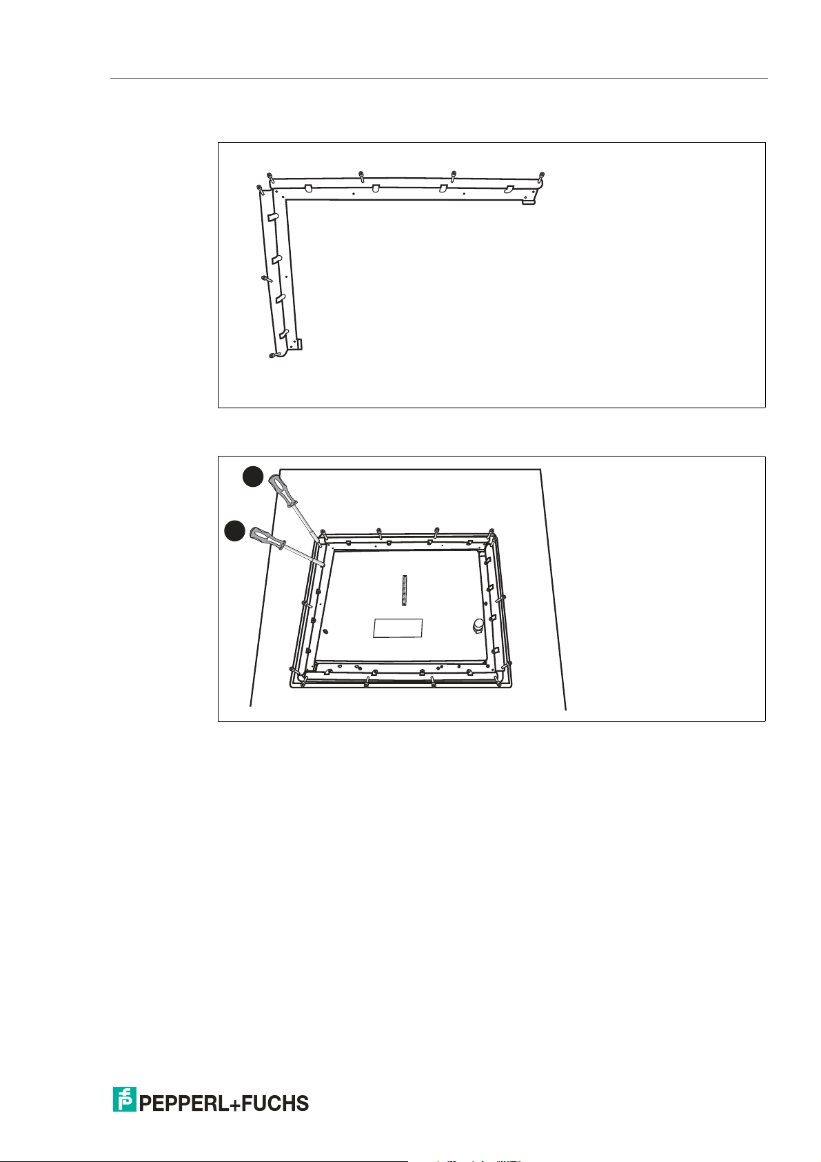
Prepare the other L-shaped bracket with the mounting screws.
5.
Mount the prepared L-shaped bracket to the display unit housing (1), then affix both L-shaped
brackets with all screws to the stiffener frame (2).
6.
Tighten all screws in a criss-cross pattern using 1.8 Nm torque for the 14 x M5 x 25 socket head
cap screws and 4 Nm for the 10 x M5 lock nuts.
2020-09
65
Page 66

VisuNet GXP
Mechanical Installation
Flush Mount Installation
The VisuNet GXP can also be flush mounted. With this mounting option (-NN), no bezel is
installed, and the monitor is recessed into the installation surface. This mounting must be done
from the back of the housing, and the fitting is kept inside the surface of the wall. The cutout
dimensions and stud location must match those on the GXP exactly.
Figure 3.34 VisuNet GXP flush mounted
Note
For more options and accessories, contact your local Pepperl+Fuchs sales representative.
66
2020-09
Page 67

VisuNet GXP
Appendix
4 Appendix
4.1 Accessories
Mounting and Installation
Item Number Type Code Description
548003 PEDESTAL-XX00-124-3-304-
548306 PEDESTAL-XX00-124-4-304-
548071 WALL-BRACKET-XX00-3-
548004 KIT-PM-XX00-22F-304-N0 Kit for panel mounting
TRN-N0
TRN-N0
304-N0
Swivel pedestal, floor mount
Compatible with AG-XX00-*
housing
3 cable glands
Swivel pedestal, floor mount
Compatible with AG-XX00-*
housing
4 cable glands
Adapter for wall mounting
installation
Compatible with AG-XX00-*
housing
Compatible with 21.5 inch
DPU (option 22F)
Peripherals
Item Number Type Code Description
Contact sales for individual
configuration
Contact sales for model selection
Contact sales for model selection
548333 CBL-IDMx60-D-J1-S-S18-N0 Cable for connecting IDM-Z1-
548334 CBL-IDMx60-D-J1-S-C38-N0 Cable for connecting IDM-Z1-
548267 SCANNER-HOLDER-U1-
548396 HOLDER-BRACKET-XX00-
2020-09
EXTA2 product family Keyboard and mouse system
Mounting options for Zone
1/21 hazardous locations
IDM-Z1-x60-D-* Corded 1-D and 2-D handheld
reader for Zone 1/21
IDM-Z1-x61-M-* Bluetooth 1-D and 2-D hand-
held reader for Zone 1/21
x60-D-* barcode readers to
the VisuNet GXP
Length: 1.8 m
x60-D-* barcode readers to
the VisuNet GXP
Length: 3.8 m
XX00-N0
IDMx61-B-N
Scanner holder compatible
with AGXX00 housing Material: stainless steel AISI 316L
(1.4404) Compatible with
IDM-Z1-6x, IDM-6x, ecom
Ident-Ex 01, and PSCAN Prepared for mounting to right
side of housing
Bracket to mount IDM-Z1-x61B-J1-BT-N0 base station to
AG-XX00 housing
Material: stainless steel AISI
304 (1.4301)
Assembly: right side of AG1
housing Includes bracket and
installation materials
Note: base station and cables
not included!
67
Page 68

VisuNet GXP
Appendix
Note
For more options and accessories, contact your local Pepperl+Fuchs sales representative.
68
2020-09
Page 69

Pepperl+Fuchs Qua lit y
Download our latest poli cy he re:
www.pepperl-fuchs.com/quali ty
© Pepperl+Fuchs · Subject to modifications
www.pepperl-fuchs.com
Printed in Germany / DOCT-5482C
 Loading...