

Page 1
Dieses Dokument enthält sicherheitsrelevante Angaben. Es darf nicht ohne Absprache mit dem Normenexperten (NE Ex) geändert werden!
This document contains safety-relevant information. It must not be altered without the authorization of the norm expert (NE Ex) !
CONFIDENTIAL acc. to ISO 16016
Only valid as long as released in EDM
date: 2017-Sep-08
Control Drawing
R2-SP-IC*
116-0406
Worldwide
sheet 1 of 3
Control drawing / Instruction manual
Segment Protector
R2-SP-IC*
Pepperl+Fuchs GmbH
Lilienthalstrasse 200
Document No.:116-0406
68307 Mannheim, Germany
Edition: 09/2017
Tel.: +49 621 776-0
UL File Number: E106378
Fax.: +49 621 776-1000
(previously UL File Number E326119)
Copyright Pepperl+Fuchs, 2017
www.pepperl-fuchs.com
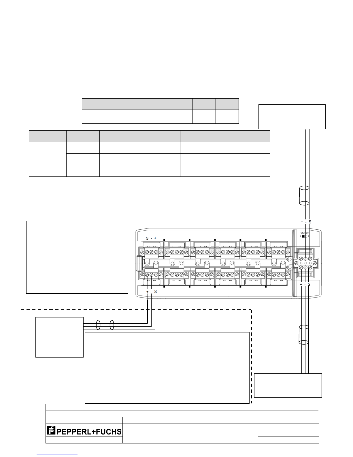
Nonincendive
field wiring
apparatus or
intrinsically safe
apparatus
①②⑧
HAZARDOUS (CLASSIFIED) LOCATION
Class l, Zone 2, Groups llB, llA
Class l, Division 2, Groups C, D
(Vin = 9-35 V with Switch in position 2)
Class I, Zone 2, Groups IIC, IIB, IIA
Class I, Division 2, Groups A, B, C, D
(Vin = 9-35 V with Switch in position 1)
Class I, Zone 2, Groups IIC, IIB, IIA
Class I, Division 2, Groups A, B, C, D
(Vin = 9-24 V with Switch in position 2)
Fieldbus Power Supply
with integrated or
external Terminator
④
⑤
①
⑧
⑤
⑩
⑥
Fieldbus Spur wiring
Model Name
Voc/U0
Isc/I0 [mA]
Ca/C0
[nF]
La/L0
[mH]
Switch 1
position
Gas/Dust groups
R2-SP-IC*
V
in
*
≤ 32 V
65
60
0.25
Position 2
IIB/IIA / IIIC/IIIB/IIIA
C, D, F, G
V
in
*
≤ 32 V
46
60
0.125
Position 1
IIC/IIB/IIA / IIIC/IIIB/IIIA
A, B, C, D, F, G
V
in
*
≤ 24 V
65
60
0.25
Position 2
IIC/IIB/IIA / IIIC/IIIB/IIIA
A, B, C, D, F, G
*
Vin = output voltage of the Fieldbus Power Supply
WARNING: Ignition hazard - Switch Position must be set correctly for the intended gas group as specified in the
Fieldbus Spur Wiring Table.
AVERTISSEMENT : Risque d'inflammation – la position du commutateur doit être correctement réglée pour le groupe
de gaz concerné, comme indiqué dans le tableau de câblage des sorties du bus de terrain.
Fieldbus Trunk wiring
Model
Name
V
max/Vin
Um
I
max
R2-SP-IC*
24 V or 32 V
see Fieldbus Spur wiring table
35 V
≤ 8 A
Next Segment Protector
or Terminator
③⑧⑨
⑥
②⑦
⑨
HAZARDOUS (CLASSIFIED) LOCATION
Class l, Zone 2, Gps. llB, llA; Class II, Zone 22, Gps. IIIC, IIIB, IIIA
Class l, Division 2, Gps. C, D; Class II, Division 2, Gps. F, G
(Vin = 9-35 V with Switch in position 2)
Class I, Zone 2, Gps. IIC, IIB, IIA; Class II, Zone 22, Gps. IIIC, IIIB, IIIA
Class I, Division 2, Gps. A, B, C, D; Class II, Division 2, Gps. F, G
(Vin = 9-35 V with Switch in position 1)
Class I, Zone 2, Gps. IIC, IIB, IIA; Class II, Zone 22, Gps. IIIC, IIIB, IIIA
Class I, Division 2, Gps. A, B, C, D; Class II, Division 2, Gps. F, G
(Vin = 9-24 V with Switch in position 2)
Page 2

Dieses Dokument enthält sicherheitsrelevante Angaben. Es darf nicht ohne Absprache mit dem Normenexperten (NE Ex) geändert werden!
This document contains safety-relevant information. It must not be altered without the authorization of the norm expert (NE Ex) !
CONFIDENTIAL acc. to ISO 16016
Only valid as long as released in EDM
date: 2017-Sep-08
Control Drawing
R2-SP-IC*
116-0406
Worldwide
sheet 2 of 3
①
Nonincendive field wiring apparatus or intrinsically safe apparatus must be suitable for the ambient
temperature and be wired and separated in accordance with the wiring methods of National Electrical
Code ANSI/NFPA 70, Canadian Electrical Code C22.1 or in accordance with the authority having
jurisdiction.
②
Spur connections allow the interconnection of nonincendive field wiring apparatus or intrinsically safe
apparatus with an associated nonincendive field wiring apparatus (Segment Protector) not specifically
examined in combination as a system when V
max
or Ui ≥ Voc or U0; Ca or Co ≥ Ci + C
cable
; La or Lo ≥ Li +
L
cable
.
③
For nonincendive applications the output voltage of the fieldbus power supply has to be safely limited
according to ANSI/ISA-12.12.01-2013.
④
Isc/I0 current can be switched beween 46 mA and 65 mA (parameters see table “Fieldbus Spur wiring”).
WARNING: Ignition hazard - Switch position must be set correctly for the intended gas group as
specified in the Fieldbus Spur Wiring Table.
AVERTISSEMENT : Risque d'inflammation – la position du commutateur doit être correctement réglée
pour le groupe de gaz concerné, comme indiqué dans le tableau de câblage des sorties du bus de
terrain.
⑤
Trunk and spur connectors are only allowed to be manipulated at ambient temperatures between –5 °C
and +70 °C.
⑥
Trunk wiring between the source and the segment protector(s) shall be installed per the Class l,
Division 2 wiring methods specified by the National Electrical Code ANSI/NFPA 70 or Canadian
Electrical Code C22.1.
⑦
Special conditions for safe use:
The use of the Switch is only permitted in the absence of a hazardous atmosphere.
All cables have to be fixed.
The signal lines of any spur must not be connected to earth potential or to the cable shield.
⑧
Usage of the segment protector in FISCO systems:
In combination with the use of a fieldbus power supply with a maximum output voltage of 17.5 V with a
safe output voltage limiting acc. to at least Ex ic the segment protector outputs are rated acc. to the
FISCO model.
Regarding the cable parameters, the cable used for the fieldbus has to be within the following ranges:
- R' = 15...150 Ohm/km (loop resistance)
- L' = 0.4...1 mH/km
- C' = 45...200 nF/km (incl. a possibly existing shield)
- C' = C'wire/wire + 0.5 * C'wire/shield (with floating field apparatus)
- C' = C'wire/wire + C'wire/shield (if the shield is connected to one pole of the fieldbus devices
supply circuit)
On each output circuit a maximum cable length of 1 km for group IIC and 5 km for groups IIA, IIB and
IIIC may be connected. If more than one device is connected, the spur cable to each device must be
shorter than 60 m. The maximum cable length must include all spur cables.
⑨
A field terminator shall be mounted at each end of the trunk.
⑩
Spur outputs of the R2-SP-IC* Segment Protector for use in a FISCO ic system require a separation
wall to be mounted on top of the Segment Protector. The separation wall is a mandatory prerequisite to
ensure the required clearance of 50 mm between the trunk terminals and the spur terminals for FISCO
ic.
WARNING: Substitution of components may impair intrinsic safety and suitability for hazardous (classified)
locations.
AVERTISSEMENT : le remplacement des composants peut altérer la sécurité intrinsèque et l'adéquation à
une utilisation dans des zones dangereuses (classées).
WARNING: Explosion Hazard – Do not disconnect incendive circuits while they are live unless area is known
to be non-hazardous.
AVERTISSEMENT: Risque d'explosion - Ne pas débrancher tant que le circuit incendiaire est sous tension,
à moins qu’il ne s’agisse d’un emplacement non dangereux.
Page 3

Dieses Dokument enthält sicherheitsrelevante Angaben. Es darf nicht ohne Absprache mit dem Normenexperten (NE Ex) geändert werden!
This document contains safety-relevant information. It must not be altered without the authorization of the norm expert (NE Ex) !
CONFIDENTIAL acc. to ISO 16016
Only valid as long as released in EDM
date: 2017-Sep-08
Control Drawing
R2-SP-IC*
116-0406
Worldwide
sheet 3 of 3
General requirements:
1. The device must be supplied by a Class 2 or limited-energy source in accordance with UL 61010-1,
Third Edition.
2. The device is an OPEN type equipment that must be used within a suitable end-use enclosure. The
suitability of the enclosure is subject to investigation by the local authority having jurisdiction at the
time of installation. The temperature inside the enclosure shall not exceed the permissible ambient
temperature of the device.
3. The device is designed for use in altitudes up to 2000 m.
4. The device is designed for use in an ambient temperature range from -50 °C up to 70 °C.
5. The maximum specified relative humidity is 95 % not condensing.
6. Protection of the operating personnel and the overall system is not ensured if the product is not
being used according to its intended purpose.
 Loading...