

Pepperl+Fuchs PXV***-F200-SSI-V19 Series Manual

FACTORY AUTOMATION
MANUAL
PXV...-F200-SSI-V19
DataMatrix Positioning System

PXV...-F200-SSI-V19
With regard to the supply of products, the current issue of the following document is ap-
plicable: The General Terms of Delivery for Products and Services of the Electrical Indus-
try, published by the Central Association of the Electrical Industry (Zentralverband
Elektrotechnik und Elektroindustrie (ZVEI) e.V.) in its most recent version as well as the
supplementary clause: "Expanded reservation of proprietorship"

PXV...-F200-SSI-V19
1 Introduction................................................................................. 4
1.1 Content of this Document ................................................................... 4
1.2 Target Group, Personnel...................................................................... 4
1.3 Symbols Used ...................................................................................... 4
2 Product Description ................................................................... 6
2.1 Use and Application ............................................................................ 6
2.2 USB Interface ....................................................................................... 6
2.3 SSI Interface ......................................................................................... 7
2.4 LED Indicators and Controls............................................................... 7
2.5 Accessories.......................................................................................... 9
3 Installation................................................................................. 10
3.1 Affixing the Code Tape....................................................................... 10
3.2 Mounting the Reader ......................................................................... 12
3.3 Electrical Connection ........................................................................ 14
4 Commissioning......................................................................... 17
4.1 Aligning the Reader ........................................................................... 17
4.2 Parameterization ................................................................................ 17
4.2.1 Internal Parameterization Using Parameterization Software............. 17
4.2.2 External Parameterization Using Code Cards.................................. 18
5 Operation and Communication............................................... 20
5.1 Communication via the SSI Interface .............................................. 20
6 Appendix ................................................................................... 22
6.1 Code Cards for External Parameterization...................................... 22
6.1.1 Code Cards with Special Functions ................................................. 22
6.1.2 Code Cards for Adjusting the Resolution ......................................... 24
6.1.3 Code Cards for Setting the Orientation ............................................ 27
6.1.4 Code cards for Setting the Transfer Rate.......................................... 28
6.1.5 Code Cards for Adjusting Input/Output 3 ......................................... 30
3

PXV...-F200-SSI-V19
Introduction
1 Introduction
1.1 Content of this Document
This document contains information required to use the product in the relevant phases of the
product life cycle. This may include information on the following:
Product identification
Delivery, transport, and storage
Mounting and installation
Commissioning and operation
Maintenance and repair
Troubleshooting
Dismounting
Disposal
Note!
Visit www.pepperl-fuchs.com to access further documentation for full information about the
product.
The documentation comprises the following parts:
This document
Datasheet
In addition, the documentation may comprise the following parts, if applicable:
EU-type examination certificate
EU declaration of conformity
Attestation of conformity
Certificates
Control drawings
Instruction manual
Other documents
1.2 Target Group, Personnel
Responsibility for planning, assembly, commissioning, operation, maintenance, and
dismounting lies with the plant operator.
Only appropriately trained and qualified personnel may carry out mounting, installation,
commissioning, operation, maintenance, and dismounting of the product. The personnel must
have read and understood the instruction manual and the further documentation.
Prior to using the product make yourself familiar with it. Read the document carefully.
2017-11
4
PXV...-F200-SSI-V19
Introduction
1.3 Symbols Used
This document contains symbols for the identification of warning messages and of informative
messages.
Warning Messages
You will find warning messages, whenever dangers may arise from your actions. It is
mandatory that you observe these warning messages for your personal safety and in order to
avoid property damage.
Depending on the risk level, the warning messages are displayed in descending order as
follows:
Danger!
This symbol indicates an imminent danger.
Non-observance will result in personal injury or death.
Warning!
This symbol indicates a possible fault or danger.
Non-observance may cause personal injury or serious property damage.
Caution!
This symbol indicates a possible fault.
Non-observance could interrupt the device and any connected systems and plants, or result in
their complete failure.
Informative Symbols
Note!
This symbol brings important information to your attention.
Action
This symbol indicates a paragraph with instructions. You are prompted to perform an action or
a sequence of actions.
2017-11
5
PXV...-F200-SSI-V19
000 009.0 m PXV-AA25
www.pepperl-fuchs.com
Y
Z
X
Product Description
2 Product Description
2.1 Use and Application
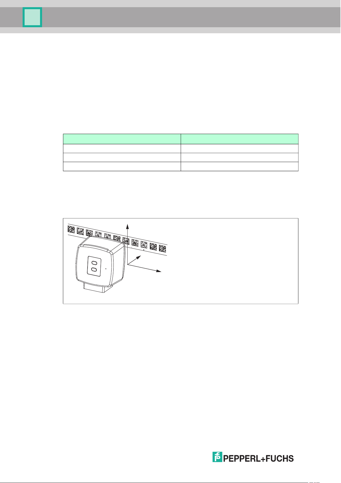
The Data Matrix Positioning System is the positioning system in the Pepperl+Fuchs incident
light process. The heart of the system is the reader, which has features including a camera
module with an integrated illumination unit. This enables the reader to detect position markers
printed onto a self-adhesive code tape in the form of 2-D Data Matrix codes.
The code tape is mounted on a fixed part of the plant (e.g., the wall of an elevator shaft or the
rail on a monorail conveyor). The reader is mounted on a moving "vehicle" positioned in
parallel with the code tape (e.g., on the elevator cab or on the chassis of a monorail conveyor).
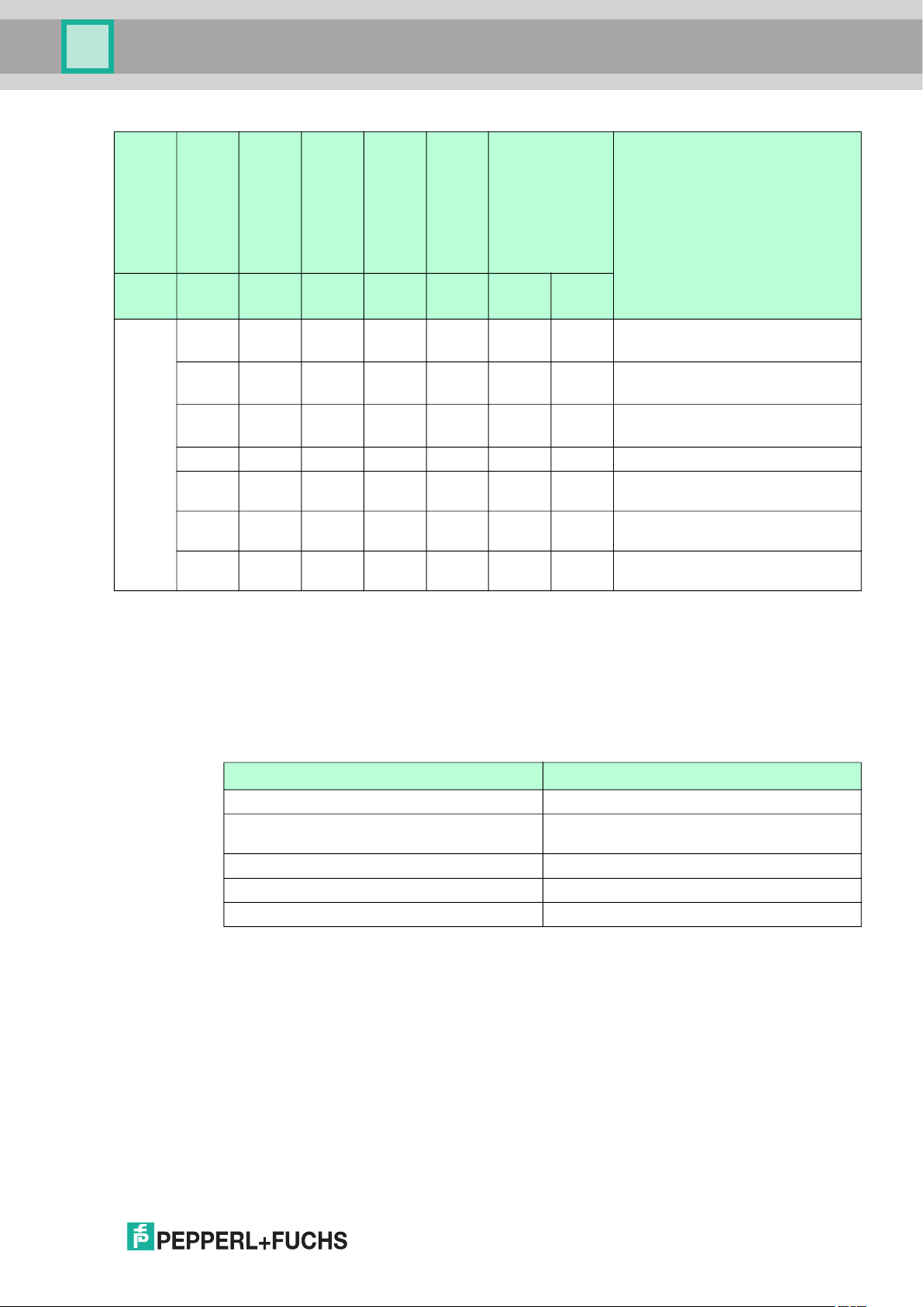
Maximum Length of the Code Tape
Resolution of the Reader [mm] Maximum length of the Code Tape [km]
10 10
1 10
0.1 1.5
The code tape length of up to 10 km is sufficient for even very large applications. It also offers
sufficient reserves for extensions or systems with several branches and parallel conveyor
routes.
The extensive yet user-friendly parameterization options as well as the freely configurable
inputs and outputs mean that the reader can easily be adapted to suit each application.
Figure 2.1 Schematic diagram of the alignment of the code tape and reader
2.2 USB Interface
The Vision Configurator is a useful and easy-to-use piece of configuration software for
configuring the reader. This configuration software is available as a free download from
www.pepperl-fuchs.com. Follow the instructions that appear on your screen during the
installation.
Use the parameterization cable (see Accessories) to establish the requisite connection to the
PC and to power the reader. The parameterization cable also provides the electrical supply for
the reader during the parameterization process. The reader is connected to the "Service"
connector.
2017-11
6
PXV...-F200-SSI-V19
COM
SSI DATA / CONFIG
OUT2 / ADJ Y
OUT3 / ADJ Z
PWR / ADJ
ERR / NO CODE
INTERNAL
DIAGNOSTIC
ADJUST
CONFIG
1
2
LED 1 2 3 4 5 6 7
Product Description
Connecting the Service Interface
1. First connect the round plug connector to the reader.
2. Connect the plug-in power supply to the parameterization cable.
3. Connect the plug-in power supply to a socket.
The ring light of the reader and the LED2 "PWR/ADJ/ERR/NO CODE" lights up
continuously or flashes.
4. Now connect the USB plug-in connector to your PC.
2.3 SSI Interface
The controller and reader communicate via the SSI interface during operation. This is an
optically isolated RS422 interface. The controller sends a series of pulses via the clock+ and
clock- lines, and the reader responds synchronously with the 25-bit comprehensive response
telegram. You can define the structure and content of the response telegram using the Vision
Configurator configuration software.
This may include position data in an X- and Y-direction as well as speed and diagnostic data.
During live operation, the reader is connected for communication via the SSI interface using
the "Main" connector.
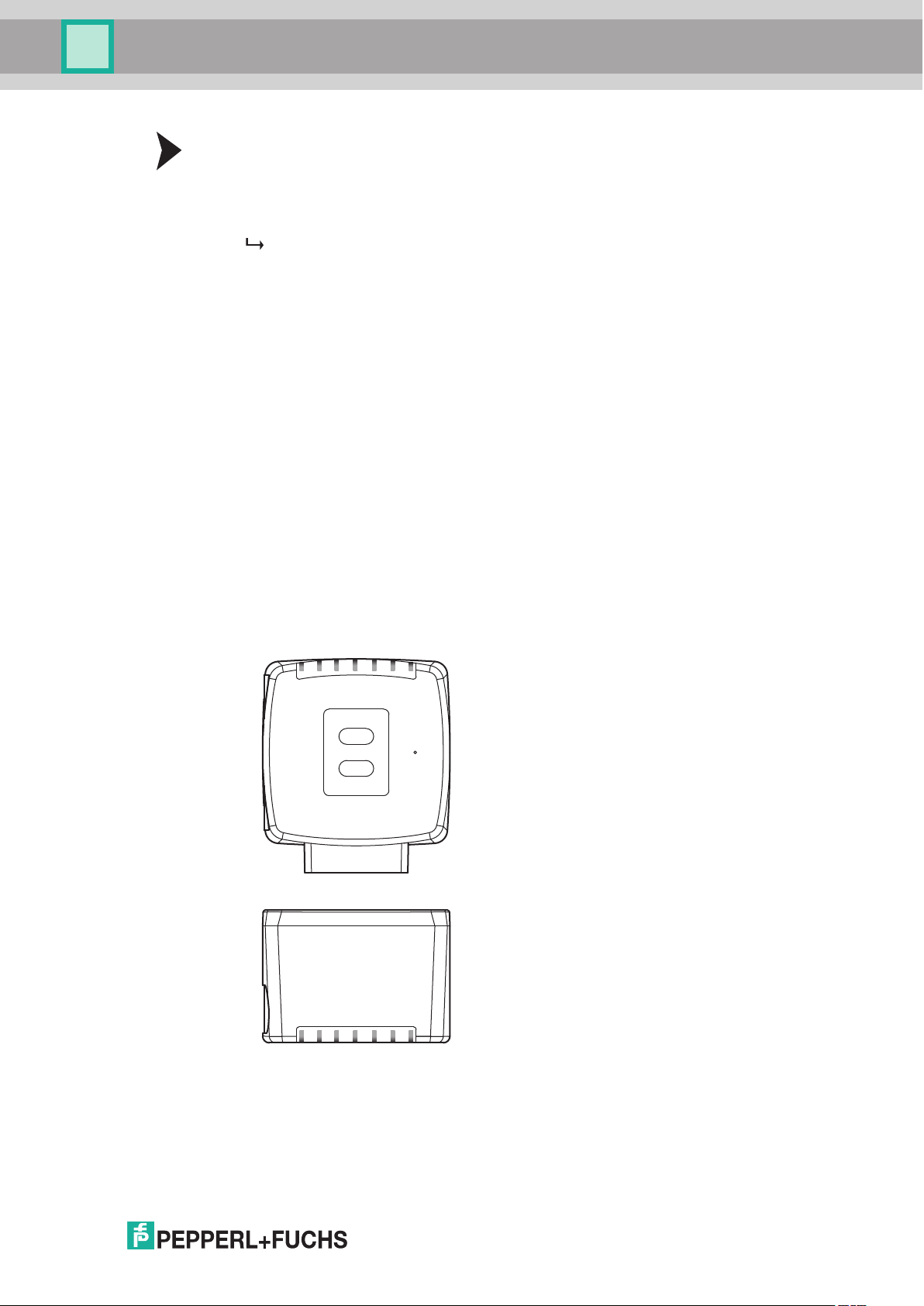
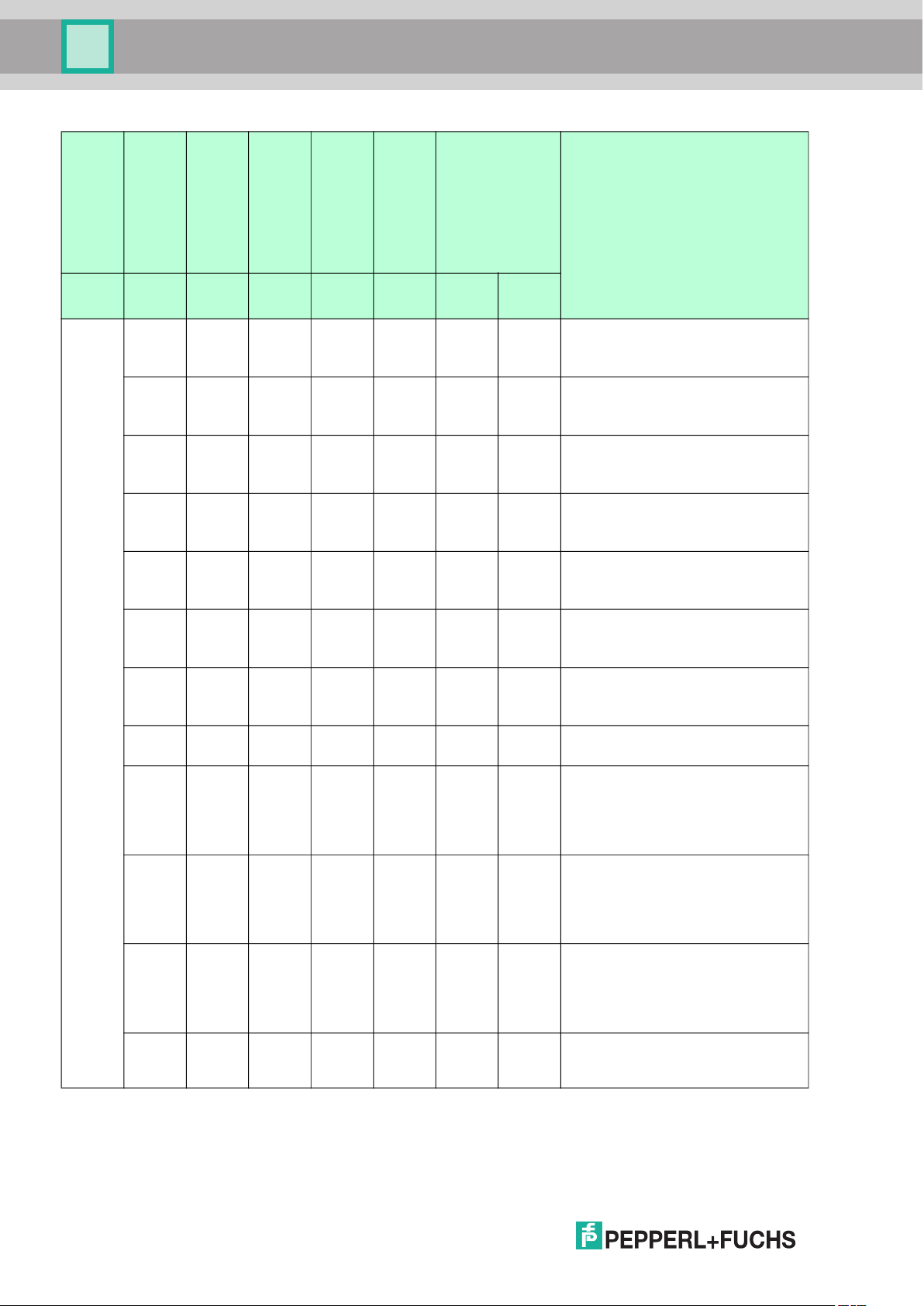
2.4 LED Indicators and Controls
The reader has seven indicator LEDs for carrying out visual function checks and rapid
diagnosis.
Using the two control buttons on the rear of the device, you can activate the alignment aid and
the parameterization mode.
Button 1 is labeled "ADJUST." Button 2 is labeled "CONFIG."
2017-11
7
PXV...-F200-SSI-V19
Product Description
LED
Status
[#1]
COM
[#2]
PWR/ADJ
(Green/
red)
Off Flashes
green
Off Flashes
green
Off Flashes
green
Off Flashes
green
Off Flashes
green
Off Flashes
green
Off Flashes
red
Off Lights
up red
Off Lights
up
green
Off Flashes
red
Off Flashes
red
Flashes Flashes
red
ERR/NO CODE
[#3]
SSI DATA/CONFIG
[#4]
OUT 2/ADJ Y
[#5]
OUT 3/ADJ Z
(yellow) (yellow) (yellow) (yellow) (yellow)
[#6] +[#7]
Internal diagnostics
DescriptionColor Yellow
Off Off Off Off Off Alignment
Y > setpoint value
f
= 2 Hz
flash
Off On Off Off Off Alignment
Y < setpoint value
= 2 Hz
f
flash
Off Flashes Off Off Off Alignment
Y = setpoint value
= 2 Hz
f
flash
Off Off Off Off Off Alignment
Z > setpoint value
= 2 Hz
f
flash
Off Off On Off Off Alignment
Z < setpoint value
= 2 Hz
f
flash
Off Off Flashes Off Off Alignment
Z = setpoint value
= 2 Hz
f
flash
Off Off Off Off Off Alignment
Code tape outside read range
= 2 Hz
f
flash
Off Off Off Off Off System error
Flashes x x Off Off Normal operation, SSI
communication active
= 2 Hz
f
flash
LEDs marked with x indicate the
status of the relevant output.
Flashes x x Off Off No code within read range,
communication active
f
= 2 Hz
flash
LEDs marked with x indicate the
status of the relevant output.
Off x x Off Off No code within read range, no SSI
communication
= 2 Hz
f
flash
LEDs marked with x indicate the
status of the relevant output.
Flashes Flashes Flashes Off Off Normal operation. Indication for two
seconds if a button is pressed when
the time lock is enabled.
2017-11
8
PXV...-F200-SSI-V19
Product Description
LED
[#1]
COM
[#2]
PWR/ADJ
ERR/NO CODE
(Green/
red)
Off Off Flashes Off Off Off Off Configuration mode active
Off Red, 3
sec
Off Green,
1 sec
x Off x x x Off Off Time lock for buttons disabled
Flashes Green Off Off Off Off Off Position query via USB interface,
Flashes Flashes
red
x x x x x Lights upLights upInternal error
x = LED status has no meaning.
(yellow) (yellow) (yellow) (yellow) (yellow)
Flashes Off Off Off Off Code card faulty
Flashes Off Off Off Off Code card detected
Off Off Off Off Off Position query via USB interface,
2.5 Accessories
Compatible accessories offer you potential for cost savings when commissioning, replacing,
and servicing our products.
[#3]
SSI DATA/CONFIG
[#4]
OUT 2/ADJ Y
[#5]
OUT 3/ADJ Z
[#6] +[#7]
Internal diagnostics
DescriptionColor Yellow
f
flash
f
flash
f
flash
code within the read range
no code within read range
Return to Pepperl+Fuchs
= 2 Hz
= 2 Hz
= 2 Hz
If products are used in harsh ambient conditions, appropriate Pepperl+Fuchs accessories can
be used to extend the service life of these products.
Model number Description
V19-G-ABG-PG9-FE Grounding terminal and plug (set)
PCV-KBL-V19-STR-USB Cable unit for service interface with power
supply
VAZ-V1S-B Cap for service connector
PCV-MB1 Mounting bracket
Vision Configurator Configuration software
Suitable connection cables can be found in the Accessories section of the reader datasheet at
www.pepperl-fuchs.com.
2017-11
9
PXV...-F200-SSI-V19
715
25
5
20
3
Installation
3 Installation
3.1 Affixing the Code Tape
The code tape is made of silicone-free polyester film. A position marker appears every 100 mm
along the lower edge of the code tape (see "Code Tape Dimensions"). These position markers
are used to affix the code tape in the correct position.
The back of the code tape is covered with a modified acrylate-based adhesive designed for
permanent adhesion. Affix the self-adhesive code tape along the desired traverse distance. To
do so, proceed as follows:
Affixing the Code Tape
1. Clean the surface of any greasy or oily deposits and dust.
2. Ensure that the surface is dry, clean, and stable.
3. Pull away a few centimeters of the protective film at the beginning of the code tape. Place
the code tape at the precise point of the required starting position on the surface, and press
to attach.
4. Then affix the code tape along the desired traverse distance. Remove the protective film
gradually so that the code tape does not accidentally adhere to the surface in the incorrect
position. When affixing, ensure that the code tape does not crease or trap air bubbles.
The adhesive on the code tape hardens after 72 hours.
Note!
Thermal Expansion of the Code Tape
The heat expansion coefficient of the adhered code tape corresponds to the heat expansion
coefficient of the underside.
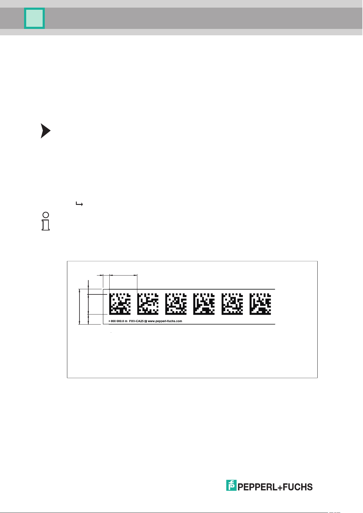
Dimensions of the Code Tape
2017-11
10
PXV...-F200-SSI-V19
000 009.0 m
0
00 009.0 m
1 2
Installation
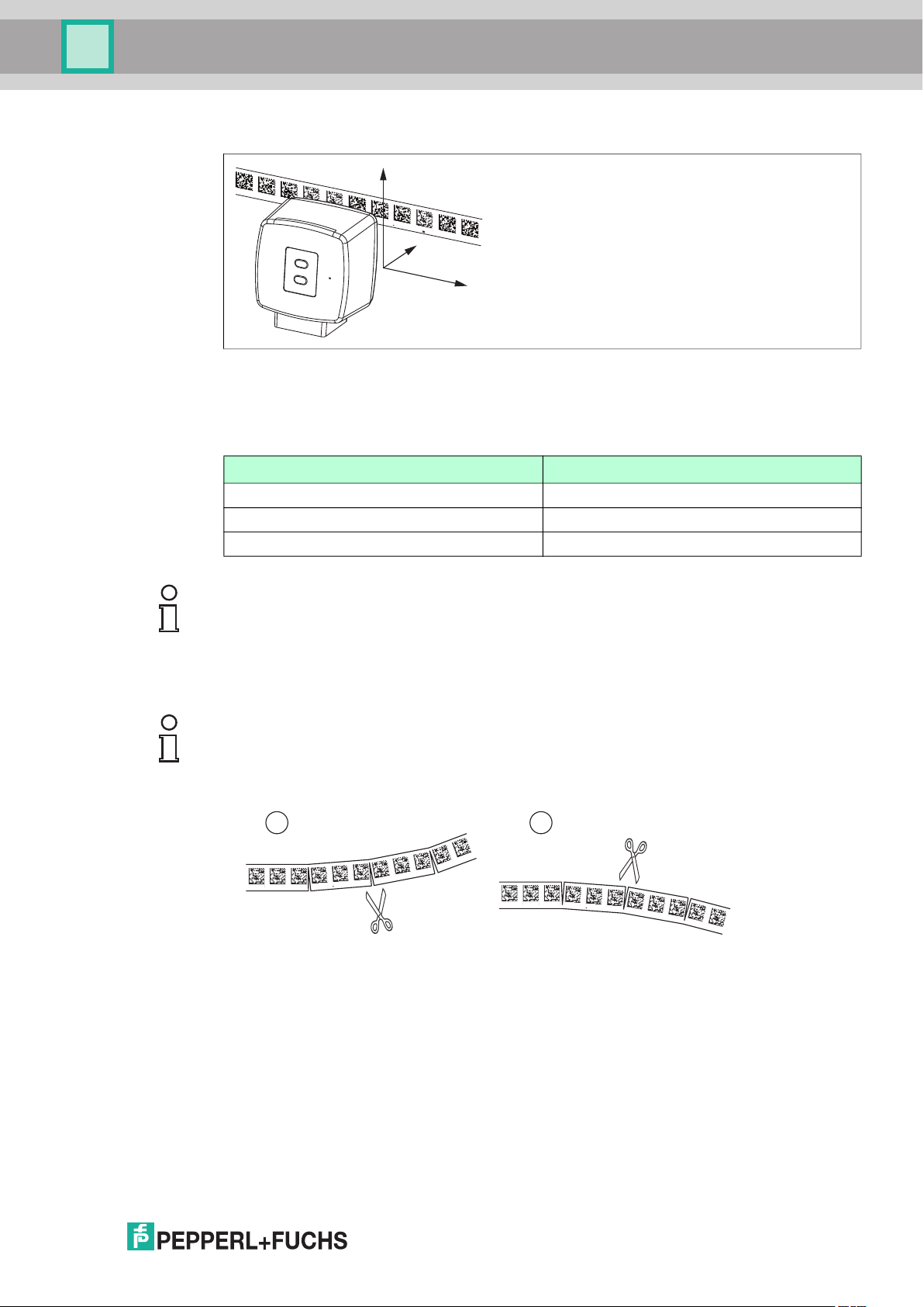
Alignment of the Code Tape and Reader
Position the code tape so that the PEPPERL+FUCHS logo and position markers are below the
data matrix code. The position values then increase along the X direction. The diagram shows
the orientation of a reader in the default setting of 0°. The reader can be configured in the
interface for other installation situations.
Code Tapes with a Starting Position of 0 m
Order Designation Description
PXV00001-CA25-* Code tape, 1-track, length: 1 m
... ...
PXV100000-CA25-* Code tape, 1-track, length: 100,000 m
Y
000 009.0 m PXV-AA25
www.pepperl-fuchs.com
Z
X
Note!
Expansion Joints and Code Tapes
If the system covers longer distances, expansion joints are integrated in the system structure.
We recommend creating breaks along the code tape. The resulting gap must not exceed
75 mm.
Note!
Inclines and Declines
If you affix the code tape on inclines or declines, cut the code tape several times at the
transition point to the horizontal as shown.
1. Incline
2. Decline
2017-11
11
 Loading...