

Page 1
FACTORY AUTOMATION
MANUAL
PXV...-F200-B25-V1D
DataMatrix Positioning System
Page 2

PXV...-F200-B25-V1D
With regard to the supply of products, the current issue of the following document is ap-
plicable: The General Terms of Delivery for Products and Services of the Electrical Indus-
try, published by the Central Association of the Electrical Industry (Zentralverband
Elektrotechnik und Elektroindustrie (ZVEI) e.V.) in its most recent version as well as the
supplementary clause: "Expanded reservation of proprietorship"
Page 3

PXV...-F200-B25-V1D
1 Introduction................................................................................. 4
1.1 Content of this Document ................................................................... 4
1.2 Target Group, Personnel...................................................................... 4
1.3 Symbols Used ...................................................................................... 5
2 Product Description ................................................................... 6
2.1 Use and Application............................................................................. 6
2.2 USB Interface........................................................................................ 6
2.3 EtherNet/IP Interface Pin Assignment .............................................. 7
2.4 LED Indicators and Controls............................................................... 7
2.5 Accessories .......................................................................................... 9
3 Installation................................................................................. 10
3.1 Affixing the Code Tape ...................................................................... 10
3.2 Mounting of the Reader..................................................................... 12
3.3 Electrical Connection ........................................................................ 14
3.4 EtherNet/IP Connection..................................................................... 15
4 Commissioning......................................................................... 17
4.1 Aligning the Reader ........................................................................... 17
5 Operation and Communication ............................................... 18
5.1 Communication via EtherNet/IP ....................................................... 18
5.1.1 General Information on Communication via EtherNet/IP................... 18
5.1.2 Setting the IP Address ..................................................................... 18
5.1.3 EtherNet/IP Objects ......................................................................... 21
5.1.4 Attributes of the Reader's EtherNet/IP Objects ................................ 22
6 Appendix ................................................................................... 28
6.1 ASCII Table.......................................................................................... 28
3
Page 4

PXV...-F200-B25-V1D
Introduction
1Introduction
1.1 Content of this Document
This document contains information required to use the product in the relevant phases of the
product life cycle. This may include information on the following:
Product identification
Delivery, transport, and storage
Mounting and installation
Commissioning and operation
Maintenance and repair
Troubleshooting
Dismounting
Disposal
Note!
Visit www.pepperl-fuchs.com to access further documentation for full information about the
product.
The documentation comprises the following parts:
This document
Datasheet
In addition, the documentation may comprise the following parts, if applicable:
EU-type examination certificate
EU declaration of conformity
Attestation of conformity
Certificates
Control drawings
Instruction manual
Other documents
1.2 Target Group, Personnel
Responsibility for planning, assembly, commissioning, operation, maintenance, and
dismounting lies with the plant operator.
Only appropriately trained and qualified personnel may carry out mounting, installation,
commissioning, operation, maintenance, and dismounting of the product. The personnel must
have read and understood the instruction manual and the further documentation.
Prior to using the product make yourself familiar with it. Read the document carefully.
2017-11
4
Page 5
PXV...-F200-B25-V1D
Introduction
1.3 Symbols Used
This document contains symbols for the identification of warning messages and of informative
messages.
Warning Messages
You will find warning messages, whenever dangers may arise from your actions. It is
mandatory that you observe these warning messages for your personal safety and in order to
avoid property damage.
Depending on the risk level, the warning messages are displayed in descending order as
follows:
Danger!
This symbol indicates an imminent danger.
Non-observance will result in personal injury or death.
Warning!
This symbol indicates a possible fault or danger.
Non-observance may cause personal injury or serious property damage.
Caution!
This symbol indicates a possible fault.
Non-observance could interrupt the device and any connected systems and plants, or result in
their complete failure.
Informative Symbols
Note!
This symbol brings important information to your attention.
Action
This symbol indicates a paragraph with instructions. You are prompted to perform an action or
a sequence of actions.
2017-11
5
Page 6
PXV...-F200-B25-V1D
000 009.0 m P
XV
AA25
w
ww.pe
p
per
l
fuchs
.c
om
Y
Z
X
Product Description
2 Product Description
2.1 Use and Application
The Data Matrix Positioning System is the positioning system in the Pepperl+Fuchs incident
light process. The heart of the system is the reader, which has features including a camera
module with an integrated illumination unit. This enables the reader to detect position markers
printed onto a self-adhesive code tape in the form of 2-D Data Matrix codes.
The code tape is mounted on a fixed part of the plant (e.g. the wall of an elevator shaft or the
rail on a monorail conveyor). The reader is mounted on a moving "vehicle" positioned in parallel
with the code tape (e.g. on the elevator cab or on the chassis of a monorail conveyor).
Maximum Length of the Code Tape
Resolution of the reader [mm] Maximum length of the code tape [km]
10 10
1 10
0.1 10
The code tape length of up to 10 km is sufficient for even very large applications. It also offers
sufficient reserves for extensions or systems with several branches and parallel conveyor
routes.
The extensive yet user-friendly parameterization options as well as the freely configurable
inputs and outputs mean that the reader can easily be adapted to suit each application.
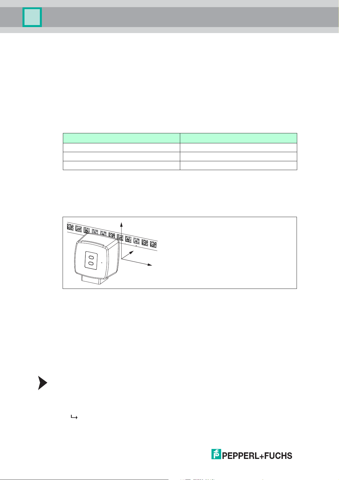
Figure 2.1 Schematic diagram of the alignment of the code tape and reader
2.2 USB Interface
The Vision Configurator is a useful and easy-to-use piece of software for configuring the read
head. This configuration software is available as a free download from www.pepperlfuchs.com. Follow the instructions that appear on your screen during the installation.
The PC connection required for programming and the read head power supply can be made
using a special parameterization cable. This parameterization cable can be ordered as an
accessory under the name "Cable unit for service interface with the power supply". This also
provides the electrical supply to the read head. The parameterization cable is connected to the
read head using the "Main" connector.
Connection of the Parameterization Cable
1. First connect the round plug connector to the read head.
2. Connect the plug-in power supply to the parameterization cable.
3. Plug the plug-in power supply into a socket.
The ring light of the read head and the "PWR/ADJ/ERR/NO CODE" LED2 lights up or
flashes.
2017-11
6
Page 7
PXV...-F200-B25-V1D
ADJUST
CONFIG
1
2
LED 1 2 3 4 5 6
Product Description
4. You can now connect the USB plug-in connector to your PC.
2.3 EtherNet/IP Interface Pin Assignment
The controller and read head communicate via the EtherNet/IP interface during operation. The
interface is based on Ethernet technology and works according to the CIP protocol (Common
Industrial Protocol).
The connection of the read head in ongoing operation is carried out via the "EtherNet/IP 1 & 2"
connectors.
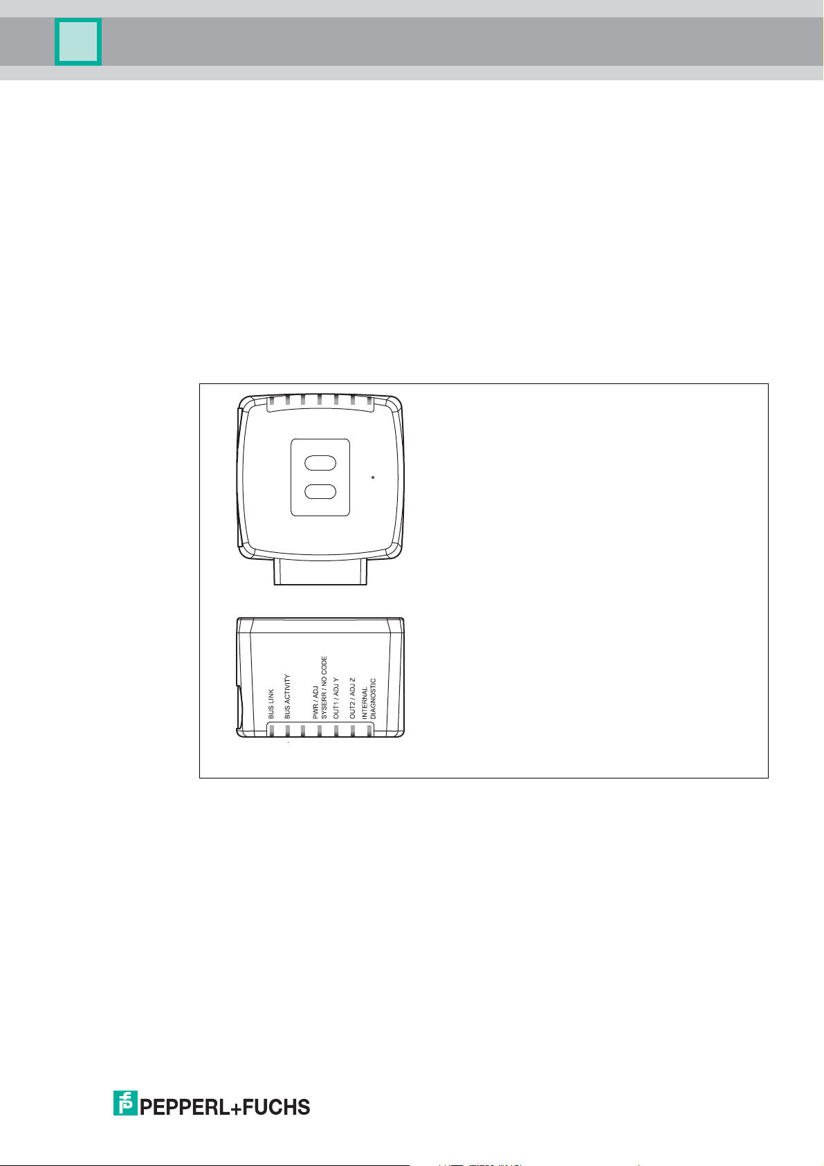
2.4 LED Indicators and Controls
The reader has six indicator LEDs for carrying out visual function checks and rapid diagnosis.
Using the two control buttons on the rear of the device, you can activate the alignment aid and
the parameterization mode.
Button 1 is labeled "ADJUST." Button 2 is labeled "CONFIG."
2017-11
Figure 2.2 Overview of LED indicators and controls
7
Page 8

PXV...-F200-B25-V1D
Product Description
[#3]
PWR/ADJ
SYSERR/NO
CODE
green
green
green
green
green
green
green
LED
[#1]
BUS
LINK
[#2]
BUS TX /
RX
Status Off Off Flashes
Off Off Flashes
Off Off Flashes
Off Off Flashes
Off Off Flashes
Off Off Flashes
Off Off Flashes red Off Off Off Alignment
x x Lights up red x x x System error
x x Lights up
Lights up x x x x x EtherNet/IP-
x Flashes x x x x EtherNet/IP TX/RX
x x Flashes red x x x Code not recognized
x x x x Lights up Lights up Internal error
[#4]
OUT
1/ADJ Y
[#5]
OUT
2/ADJ Z
[#6]
INTERNAL
DIAGNOSTIC
Red/green/
yellow
DescriptionColor Green Ye l l ow Red/green Ye l l o w Yellow
Off Off Off Alignment
Y > setpoint value
f
= 2 Hz
flash
Lights up Off Off Alignment
Y < setpoint value
f
= 2 Hz
flash
Flashes Off Off Alignment
Y = setpoint value
f
= 2 Hz
flash
Off Off Off Alignment
Z > setpoint value
f
= 2 Hz
flash
Off Lights up Off Alignment
Z < setpoint value
f
= 2 Hz
flash
Off Flashes Off Alignment
Z = setpoint value
f
= 2 Hz
flash
Code tape outside
read range
f
= 2 Hz
flash
x x x Normal operation,
code tape detected
connection active
data transfer
f
= 2 Hz
flash
Return to
Pepperl+Fuchs
x = LED status has no meaning
2017-11
8
Page 9

PXV...-F200-B25-V1D
Product Description
2.5 Accessories
Compatible accessories offer enormous potential for cost savings. Such accessories not only
save you a great deal of time and effort when commissioning for the first time, but also when
replacing and servicing our products.
If products are used in harsh ambient conditions, appropriate Pepperl+Fuchs accessories can
be used to extend the service life of these products.
Model number Description
V19-G-ABG-PG9 M12 single-ended female cordset, 8-pin, shielded, field-
V19-G-ABG-PG9-FE Grounding terminal and plug (set)
PCV-SC12
PCV-SC12A
V1SD-G-*M-PUR-ABG-V1SD-G Ethernet bus cable, M12 to M12, available in several
VAZ-V 1S -B Stopping plug for M12 connector
V19-G-*M-* Configurable connection cable
PCV-KBL-V19-STR-USB Cable unit for service interface with power supply
Vision Configurator Software Software for camera-based sensors that enables
PCV-MB1 Mounting bracket
attachable
Grounding clip
different lengths
convenient parameterization
Further information on accessories can be found on the reader datasheet at www.pepperlfuchs.com.
2017-11
9
Page 10

PXV...-F200-B25-V1D
715
25
5
20
3
Installation
3Installation
3.1 Affixing the Code Tape
The code tape is made of silicone-free polyester film. A position marker appears every 100 mm
along the lower edge of the code tape (see "Code Tape Dimensions"). These position markers
are used to affix the code tape in the correct position.
The back of the code tape is covered with a modified acrylate-based adhesive designed for
permanent adhesion. Affix the self-adhesive code tape along the desired traverse distance. To
do so, proceed as follows:
Affixing the Code Tape
1. Clean the surface of any greasy or oily deposits and dust.
2. Ensure that the surface is dry, clean, and stable.
3. Pull away a few centimeters of the protective film at the beginning of the code tape. Place
the code tape at the precise point of the required starting position on the surface, and press
to attach.
4. Then affix the code tape along the desired traverse distance. Remove the protective film
gradually so that the code tape does not accidentally adhere to the surface in the incorrect
position. When affixing, ensure that the code tape does not crease or trap air bubbles.
The adhesive on the code tape hardens after 72 hours.
Note!
Thermal Expansion of the Code Tape
The heat expansion coefficient of the adhered code tape corresponds to the heat expansion
coefficient of the underside.
Dimensions of the Code Tape
2017-11
10
Page 11

PXV...-F200-B25-V1D
000 009.0 m P
XV
AA25
w
ww.pe
p
per
l
fuchs
.c
o
m
Y
Z
X
0
0
0
0
0
9.0
m
0
0
0
0
0
9
.
0
m
1 2
Installation
Alignment of the Code Tape and Reader
Position the code tape so that the PEPPERL+FUCHS logo and position markers are below the
data matrix code. The position values then increase along the X direction. The diagram shows
the orientation of a reader in the default setting of 0°. The reader can be configured in the
interface for other installation situations.
Code Tapes with a Starting Position of 0 m
Order Designation Description
PXV00001-CA25-* Code tape, 1-track, length: 1 m
... ...
PXV100000-CA25-* Code tape, 1-track, length: 100,000 m
Note!
Expansion Joints and Code Tapes
If the system covers longer distances, expansion joints are integrated in the system structure.
We recommend creating breaks along the code tape. The resulting gap must not exceed
75 mm.
Note!
Inclines and Declines
If you affix the code tape on inclines or declines, cut the code tape several times at the
transition point to the horizontal as shown.
1. Incline
2. Decline
2017-11
11
Page 12

PXV...-F200-B25-V1D
Y
0
X
Installation
Hysteresis Y-Axis
Figure 3.1 Zero line for code tapes
If the reader leaves the zero line when traversing along the X-axis, the threshold may deviate. If
the deviation exceeds the defined threshold, a warning code is issued.
Y-Axis Deviation Thresholds
Code Tape Threshold
Number of Tracks Width Exit Entry
1 15 mm ± 29 mm ±25 mm
3.2 Mounting of the Reader
Mounting the Reader
Make sure that you are able to mount the reader in a stable position. Before mounting the
reader, make sure that the travel of the moving system part is arranged so that this part does
not move outside of the reader's depth of focus range during operation.
1. Mount the reader on the moving part of the system and secure the reader in place using four
screws through the mounting adapter on the reader.
2. Mount the reader vertically so that the lens of the reader with the ring light and camera
module is aligned toward the code tape.
30°
30°
Code tape
Read distance
Figure 3.2 Vertical alignment tolerance
3. Alternatively, mount the reader horizontally so that the lens of the reader with the ring light
and camera module is aligned toward the code tape.
12
2017-11
Page 13

PXV...-F200-B25-V1D
30°
30°
1
70
80
38.5
70 14.5
1
2
22
50
ø 25
12.5
M12 x 1
9
4 x M6
20 20
Installation
Figure 3.3 Horizontal alignment tolerance
1 Read Distance
4. Check that the distance between the reader and the code tape is equal to the read distance
of the reader:
Optimum Read Distance (Z-Axis)
Order Designation Read Distance [mm] Depth of Focus [mm]
PXV100* 100 ± 50
Dimensions of the Reader
2017-11
13
Page 14

PXV...-F200-B25-V1D
Installation
Caution!
When selecting the length of the mounting screws, ensure that the maximum insertion depth of
the screws in the threaded inserts on the reader is 8 mm.
Using longer screws may damage the reader.
Caution!
The maximum torque of the mounting screws must not exceed 9 Nm.
Tightening the screws to a higher torque may damage the reader.
3.3 Electrical Connection
The reader is connected to an 8-pin M12 x 1 connector plug at the side of the housing with the
label "Main". This connection is used to provide the power supply and communicate with the
peripherals in one. The configurable inputs and outputs for the reader are also available on this
connection.
Main
1
2
3
4
5
6
7
8
OUT 2 / IN 2
+ UB
n.c.
n.c.
OUT 1
IN 1
GND
OUT 3 / IN 3
Plug Assignment
Main
1
8
7
2
6
53
4
Color Assignment
Pepperl+Fuchs single-ended female cordsets are manufactured in accordance with EN609475-2. When using a type V19-... single-ended female cordset with an open cable end on the
Main connection, the colors are assigned as follows:
Connection Pin Strand Color Color Abbreviation
1 White WH
2 Brown BN
3 Green GN
4 Yellow YE
5 Gray GY
6 Pink PK
7 Blue BU
8 Red RD
14
2017-11
Page 15

PXV...-F200-B25-V1D
Installation
Shielding Cables
The shielding of connection lines is required to suppress electromagnetic interference.
Establishing a low resistance or low impedance connection with the conductor or equipotential
bonding circuit is a particularly important factor in ensuring that these interference currents do
not become a source of interference themselves. Always use connection lines with braided
shield; never use connection lines with a film shield. The shield is integrated at both ends, i.e.,
in the switch cabinet or on the controller and on the read head. The grounding terminal
available as an accessory allows easy integration in the equipotential bonding circuit.
In exceptional cases, the shielding of a connection at one end may be more favorable if
An equipotential bonding cable is not laid or cannot be laid.
A film shield is used.
The following points relating to shielding must also be noted:
Use metal cable clips that cover large areas of the shield.
After installing the cable shield in the control cabinet, place it directly on the equipotential
bonding rail.
Direct the protective grounding connections to a common point in a star configuration.
The cross-section of the cables used for grounding should be as large as possible.
Additional Ground Connection
Order Designation Description
PCV-SC12 Clip for mounting an additional ground
PCV-SC12A
Caution!
Damage to the device
Connecting an alternating current or excessive supply voltage can damage the device or
cause the device to malfunction.
Electrical connections with reversed polarity can damage the device or cause the device to
malfunction.
Connect the device to direct current (DC). Ensure that the supply voltage rating is within the
specified device range. Ensure that the connecting wires on the female cordset are connected
correctly.
3.4 EtherNet/IP Connection
The reader is connected to EtherNet/IP via two 4-pin, D-coded device sockets, M12 x 1,
EtherNet/IP 1 and EtherNet/IP 2, on the side of the housing.
Bus
1
2
3
4
TX +
RX +
TX -
RX -
connection.
Figure 3.4
2017-11
15
Page 16

PXV...-F200-B25-V1D
EtherNet/IP 1 & 2
1
3
4
2
Installation
Connector Assignment
Figure 3.5
Suitable Ethernet cables can be found in the Accessories section of the reader datasheet at
www.pepperl-fuchs.com.
16
2017-11
Page 17

PXV...-F200-B25-V1D
000 009.0 m P
XV
AA25
w
ww.pe
p
per
l
f
uchs
.c
om
Y
Z
X
Commissioning
4 Commissioning
4.1 Aligning the Reader
The reader provides an integrated alignment aid to enable simple optimal alignment of the
reader relative to the code tape in the Y-coordinate and the Z-coordinate.
Note!
The alignment aid may only be activated within 10 minutes of switching on the reader.
You can also switch the reader from normal operation to parameterization mode, if necessary.
Press button 1 on the rear of the reader and hold for at least 2 seconds.
Activating the Alignment Aid
1. Press button 1 for longer than 2 seconds.
If the reader has recognized the code tape, LED2 flashes green. If the reader has not
recognized the code tape, LED2 flashes red. .
2. Align the reader in the Z and Y coordinates. The LEDs on the reader will support you.
Z coordinate:If the distance between the camera and the code tape is too small, the yellow
LED5 lights up. If the distance between the camera and the code tape is too large, the yellow
LED5 goes out. Within the target range, the yellow LED5 and the green LED2 flash
synchronously.
Set the distance between the reader and the code tape so that the yellow LED5 and the green
LED2 flash synchronously.
Y coordinate: If the optical axis of the reader is too low relative to the middle of the code tape,
the yellow LED4 lights up.
If the optical axis is too high, the yellow LED4 goes out. Within the target range, the yellow
LED4 and the green LED2 flash synchronously.
Set the optimal height of the reader relative to the code tape so that the yellow LED4 and the
green LED2 flash synchronously.
Briefly press button 1 to close the alignment aid. The reader now switches to normal operation.
2017-11
17
Page 18

PXV...-F200-B25-V1D
Operation and Communication
5 Operation and Communication
5.1 Communication via EtherNet/IP
5.1.1 General Information on Communication via EtherNet/IP
The read head communicates with the controller (e.g., PLC) via EtherNet/IP. An objectoriented fieldbus system for exchanging data between nodes based on Ethernet technology.
The management and development of the EtherNet/IP standards are subject to the Open
DeviceNet Vendor Association (ODVA). More information on EtherNet/IP will be supplied on
request by the Open DeviceNet Vendor Association (ODVA) at the following Internet address:
ODVA, Inc
4220 Varsity Drive, Suite A
Ann Arbor, MI 48108-5006 USA
http://www.odva.org e-mail: mailto:odva@odva.org
The basic properties of the interface are:
Transfer rate 10 Mbit/s or 100 Mbit/s, half or full duplex operation
Automatic negotiation of the transfer rate and the duplex method (auto-negotiation)
Automatic setting for crossed lines (auto-crossover)
EtherNet/IP protocol works according to the CIP protocol (Common Industrial Protocol) and is
used to control, configure, monitor, and collect data. Time-sensitive data exchange (implicit
messaging) takes place using the UDP/IP protocol and non-time-sensitive data exchange
(explicit messaging) using the TCP/IP protocol.
The read head supports the following features:
"Listen only", "Input only", and "Exclusive Owner" connection types
Message transmission as "Multipoint data transfer" (Multicast) and "Point-to-point data
transfer" (Unicast)
Cycle time (request packet interval) 2 ms
Dynamic Host Configuration Protocol (DHCP)
Device Level Ring (DLR)
Address Conflict Detection (ACD)
The read head is integrated in the network via a EDS file (electronic data sheet) with a
configuration tool such as RSLOGIX5000. The EDS file contains all of the information about
device-specific parameters and operating modes.
Downloading the EDS file
You can find the relevant EDS file in the Software section of the product detail page for the
device.
To access the product detail page for the device, go to http://www.pepperl-fuchs.com and type
information about the device (e.g., the product description or the item number) into the search
function.
5.1.2 Setting the IP Address
The read head is delivered in DHCP mode and waits for an address assignment from the
control system.
The following section describes the address assignment via the software BOOT/DHCP server
from Rockwell Automation as an example.
18
2017-11
Page 19

PXV...-F200-B25-V1D
Operation and Communication
1. Connect the read head with the DHCP server.
2. Start the BOOT/DHCP server software.
3. Enter the following data in the Network Settings menu:
- Subnet Mask "255.255.255.0 "
- Gateway "192.168.1.1"
- the remaining fields are not filled in.
4. Switch on the supply voltage to the read head.
The read head cyclically carries out DHCP requests. This enters the MAC address of the
read head in the Request History field to the list.
5. Enter the desired IP address in the New Entry menu.
- The software automatically adopts the MAC address of the read head.
- The "hostname" function is not supported.
- You may enter text under "Description".
2017-11
19
Page 20

PXV...-F200-B25-V1D
Operation and Communication
6. Confirm the entries of the address data using OK.
The IP address is assigned to the read head on the next DHCP request. The new
address data will be displayed in the Relation List field.
20
7. Press the Disable BOOTP/DHCP key in the Relation List field.
In this way, the assigned IP address is saved permanently in the read head.
2017-11
Page 21

PXV...-F200-B25-V1D
Operation and Communication
5.1.3 EtherNet/IP objects
All the data and functions of the read head are defined via objects in accordance with the
EtherNet/IP standards. The read head corresponds to the "Encoder Device Type 0x22" device
profile.
The read head supports the following listed standard and product-specific classes.
Standard classes
Class ID Class description
0x01 Identity Object
0x02 Message Router Object
0x04 Assembly Object
0x06 Connection Manager Object
0xF5 TCP/IP Interface Object
0xF6 Ethernet Link Object
0X47 DLR Object
0X48 Quality of Service
Product-specific class
Class ID Class description
0x23 Position Sensor Object
The parameters are not directly addressable from the network with the "Set" or "Get" attribute
services. Access is via Assembly Objects (Class Code 0x04)
2017-11
21
Page 22

PXV...-F200-B25-V1D
Operation and Communication
Cyclic data communication with assembly objects (Class Code 0x04)
Assemblies are special CIP objects used for cyclic data communication (implicit messaging).
These are composed of one or more attributes of various objects. These objects allow you to
send or receive data from multiple objects by means of a connection. The composition of the
assemblies in the read head is fixed and cannot be modified by the user.
Input assemblies
Instance
no.
1 Position 4 Position Value Signed
100 Position + speed 8 Position Value Signed
101 Status, X-position, Y-
Description Size [byte] Attribute
position, Speed,
Warning, Event
Attribute
ID
10 DINT
(X-Position)
10 DINT
(X-Position)
Velocity Value 24 DINT
18 Status Word 100 UINT
Position Value Signed
(X-Position)
Y-position 101 DINT
Velocity Value 24 DINT
Warning flags 102 UINT
Event number 103 UINT
10 DINT
Data type
Addresses required for the various connection types
The connection type defines the connection between the control system (originator), in this
case the controls, and the target device (target), in this case the read head. The following
options are available for data traffic.
Data from the control system to the destination device
Instance no. (dec.) Size [byte] Connection type
192 0 Listen only
193 0 Input only
Data from the target device to the control system
Instance no. (dec.) Size [byte] Assemblies
1 4 Position
100 8 Position + speed
101 18 Status, X-position, Y-position,
5.1.4 Attributes of the Reader's EtherNet/IP Objects
Attributes of the Position Sensor Object (Class ID 0x23)
Speed, Warning, Event (lists
only)
22
Class attributes
ID Name Access Data type Size [byte] Description
1 Revision - UINT 2 Object
inspection
2017-11
Page 23

PXV...-F200-B25-V1D
Operation and Communication
Standard instance attributes for object 0x23
ID Attribute Access Data type Size [byte] Description
10 Position Value
Signed (X
position)
24 Velocity Value - DINT 4 Velocity
Reader-specific attributes
ID Attribute Access Data type Size [byte] Description
100 Status Word - UINT 2 Status information
101 Y position - UINT 4 Y position in two's
102 Warning Flags - UINT 2 Warnings
103 Event Number - UINT 2 Event marker number
Basic data structure
- DINT 4 X position in two's
complement
complement
1byte = 8bit value
Byte 4 Byte 3 Byte 2 Byte 1
Example: XP31 ... XP24
MSB (most significant
byte)
Example: XP23
... XP16
Example: XP15
... XP08
Example: XP07 ... XP00
LSB (least significant byte)
Position data X: Position Value Signed (ID 10)
Size Type Content
4 byte consistent Input data 32 bit X data
The following default settings apply:
The X position is output in the two's complement.
The value is output in the resolution set for the device.
The default is mm.
If the ERR bit is set in the "status word (ID 100)" attribute, the error number is transferred
to this attribute.
LSB first
LSB = least significant byte
Resolution: 0.1 mm, 1 mm, 10 mm, binary coded
At a resolution of 1 mm and 10 mm: L
10,000,000 mm
10.00 km =
max =
Data for attribute 10
Bit 7 Bit 6 Bit 5 Bit 4 Bit 3 Bit 2 Bit 2 Bit 0
Byte 1 XP07 XP06 XP05 XP04 XP03 XP02 XP01 XP00
Byte 2 XP15 XP14 XP13 XP12 XP11 XP10 XP09 XP08
Byte 3 XP23 XP22 XP21 XP20 XP19 XP18 XP17 XP16
Byte 4 XP31 XP30 XP29 XP28 XP27 XP26 XP25 XP24
2017-11
23
Page 24

PXV...-F200-B25-V1D
Operation and Communication
Position data Y: Y position (ID 101)
Size Type Content
4 byte consistent Input data 32 bit Y data
The following default settings apply:
The Y position is output in the two's complement.
The value is output in the resolution set for the device.
The default is mm.
Data for attribute 101
Bit 7 Bit 6 Bit 5 Bit 4 Bit 3 Bit 2 Bit 2 Bit 0
Byte 1 YP07 YP06 YP05 YP04 YP03 YP02 YP01 YP00
Byte 2 YP15 YP14 YP13 YP12 YP11 YP10 YP09 YP08
Byte 3 YP23 YP22 YP21 YP20 YP19 YP18 YP17 YP16
Byte 4 YP31 YP30 YP29 YP28 YP27 YP26 YP25 YP24
LSB first
Resolution: 0.1 mm, 1 mm, 10 mm, binary coded in
two's complement
Speed data: Velocity Value (ID 24)
Size Type Content
4 byte consistent Input data 32 bit speed data
Resolution: 0.1 m/s, 0.01 m/s, 0.001 m/s, binary coded
Speed of 0 ... 12.5 m/s
Example: Speed = 4.7 m/s --> speed output = 47 at a
resolution of 0.1 m/s
65535 for unknown speed
The following default settings apply:
The value is output in the resolution set for the device.
The default is dm/s.
Data for attribute 24
Bit 7 Bit 6 Bit 5 Bit 4 Bit 3 Bit 2 Bit 2 Bit 0
Byte 1 SP07 SP06 SP05 SP04 SP03 SP02 SP01 SP00
Byte 2 SP15 SP14 SP13 SP12 SP11 SP10 SP09 SP08
Byte 3 SP23 SP22 SP21 SP20 SP19 SP18 SP17 SP16
Byte 4 SP31 SP30 SP29 SP28 SP27 SP26 SP25 SP24
Status: Status word (ID 100)
24
Size Type Content
2 bytes Input data 16 bit status
If the ERR bit is set, there is an error. The error number is transmitted to the "Value Signed (ID
10)" attribute.
2017-11
Page 25

PXV...-F200-B25-V1D
Operation and Communication
Data for attribute 100
Content
Byte 1, 2
Bit no.
1 ERR Error message (error code in XP00–XP15); remaining
2 NP No position information/OUT (XP = 0, YP = 0, SP = 0)
3 WRN Warnings present, see Warning attribute
4 EV Event, see Event attribute
5 Posdetected Valid position information available
... ... -
16 0 -
Error Codes
Error code Description Priority
1 Reader tilted 180° 2
2 No clear position can be determined (difference between codes
> 1000 Internal error 1
Status
is too great, code distance incorrect, etc.)
Function
bits = 0, see Error Codes
3
Event: Event Marker No. (ID 103)
Size Type Content
2 byte consistent Input data Last event marker
The event marker no. is binary coded and unsigned.
Data for attribute 103
Bit no.
1 EV01
2 EV02
3 EV03
4 EV04
5 EV05
6 EV06
7 EV07
8 EV08
9 EV09
10 0
... ...
16 0
Last event no.
Content
Byte 1, 2
Last event marker data
2017-11
25
Page 26

PXV...-F200-B25-V1D
Operation and Communication
Warning: Warning Flags (ID 102)
Size Type Content
2 byte consistent Input data Last warnings
A set bit indicates that the corresponding warning is active.
Data for attribute 102
Bit no.
1 WRN01
2 WRN02
3 WRN03
4 WRN04
5 WRN05
6 WRN06
7 WRN07
8 WRN08
9 WRN09
10 WRN10
11 WRN11
12 WRN12
13 WRN13
14 WRN14
15 WRN15
16 WRN16
Last warning no.
Content
Byte 1, 2
Last warning data
26
Warning data set
Content
Bit no.
1 WRN01 A code with content that did not come from the reader (PXV) was
2 WRN02 Reader too close to code tape
3 WRN03 Reader too far from code tape
4 WRN04 Y position too large. The sensor is just before OUT
5 WRN05 Y position too small. The sensor is just before OUT
6 WRN06 The reader is rotated or tilted in relation to the code tape
7 WRN07 Low level of code contrast
8 WRN08 Repair tape detected
9 WRN09 Temperature too high
10 WRN10 Reserved
11 WRN11 Reserved
12 WRN12 Reserved
13 WRN13 Reserved
DescriptionByte 1, 2
found.
2017-11
Page 27

PXV...-F200-B25-V1D
Operation and Communication
Content
Bit no.
14 WRN14 Reserved
15 WRN15 Reserved
16 WRN16 Reserved
Note!
If no warnings are present, all bits in the warning data set are set to 0.
DescriptionByte 1, 2
2017-11
27
Page 28

PXV...-F200-B25-V1D
Appendix
6Appendix
6.1 ASCII Table
hex dec ASCII hex dec ASCII hex dec ASCII hex dec ASCII
00 0 NUL 20 32 Space 40 64 @ 60 96 '
01 1 SOH 21 33 ! 41 65 A 61 97 a
02 2 STX 22 34 " 42 66 B 62 98 b
03 3 ETX 23 35 # 43 67 C 63 99 c
04 4 EOT 24 36 $ 44 68 D 64 100 d
05 5 ENQ 25 37 % 45 69 E 65 101 e
06 6 ACK 26 38 & 46 70 F 66 102 f
07 7 BEL 27 39 ' 47 71 G 67 103 g
08 8 BS 28 40 ( 48 72 H 68 104 h
09 9 HT 29 41 ) 49 73 I 69 105 I
0A 10 LF 2A 42 * 4A 74 J 6A 106 j
0B 11 VT 2B 43 + 4B 75 K 6B 107 k
0C 12 FF 2C 44 , 4C 76 L 6C 108 l
0D 13 CR 2D 45 - 4D 77 M 6D 109 m
0E 14 SO 2E 46 . 4E 78 N 6E 110 n
0F 15 SI 2F 47 / 4F 79 O 6F 111 o
10 16 DLE 30 48 0 50 80 P 70 112 p
11 17 DC1 31 49 1 51 81 Q 71 113 q
12 18 DC2 32 50 2 52 82 R 72 114 r
13 19 DC3 33 51 3 53 83 S 73 115 s
14 20 DC4 34 52 4 54 84 T 74 116 t
15 21 NAK 35 53 5 55 85 U 75 117 u
16 22 SYN 36 54 6 56 86 V 76 118 v
17 23 ETB 37 55 7 57 87 W 77 119 w
18 24 CAN 38 56 8 58 88 X 78 120 x
19 25 EM 39 57 9 59 89 Y 79 121 y
1A 26 SUB 3A 58 : 5A 90 Z 7A 122 z
1B 27 ESC 3B 59 ; 5B 91 [ 7B 123 {
1C 28 FS 3C 60 < 5C 92 \ 7C 124 |
1D 29 GS 3D 61 = 5D 93 ] 7D 125 }
1E 30 RS 3E 62 > 5E 94 ^ 7E 126 ~
1F 31 US 3F 63 ? 5F 95 _ 7F 127 DEL
28
2017-11
Page 29

Subject to modifications
Copyright PEPPERL+FUCHS • Printed in Germany
www.pepperl-fuchs.com
FACTORY AUTOMATION –
SENSING YOUR NEEDS
Worldwide Headquarters
Pepperl+Fuchs GmbH
68307 Mannheim · Germany
Tel. +49 621 776-0
E-mail: info@de.pepperl-fuchs.com
USA Headquarters
Pepperl+Fuchs Inc.
Twinsburg, Ohio 44087 · USA
Tel. +1 330 4253555
E-mail: sales@us.pepperl-fuchs.com
Asia Pacific Headquarters
Pepperl+Fuchs Pte Ltd.
Company Registration No. 199003130E
Singapore 139942
Tel. +65 67799091
E-mail: sales@sg.pepperl-fuchs.com
/ DOCT-5912
11/2017
 Loading...