

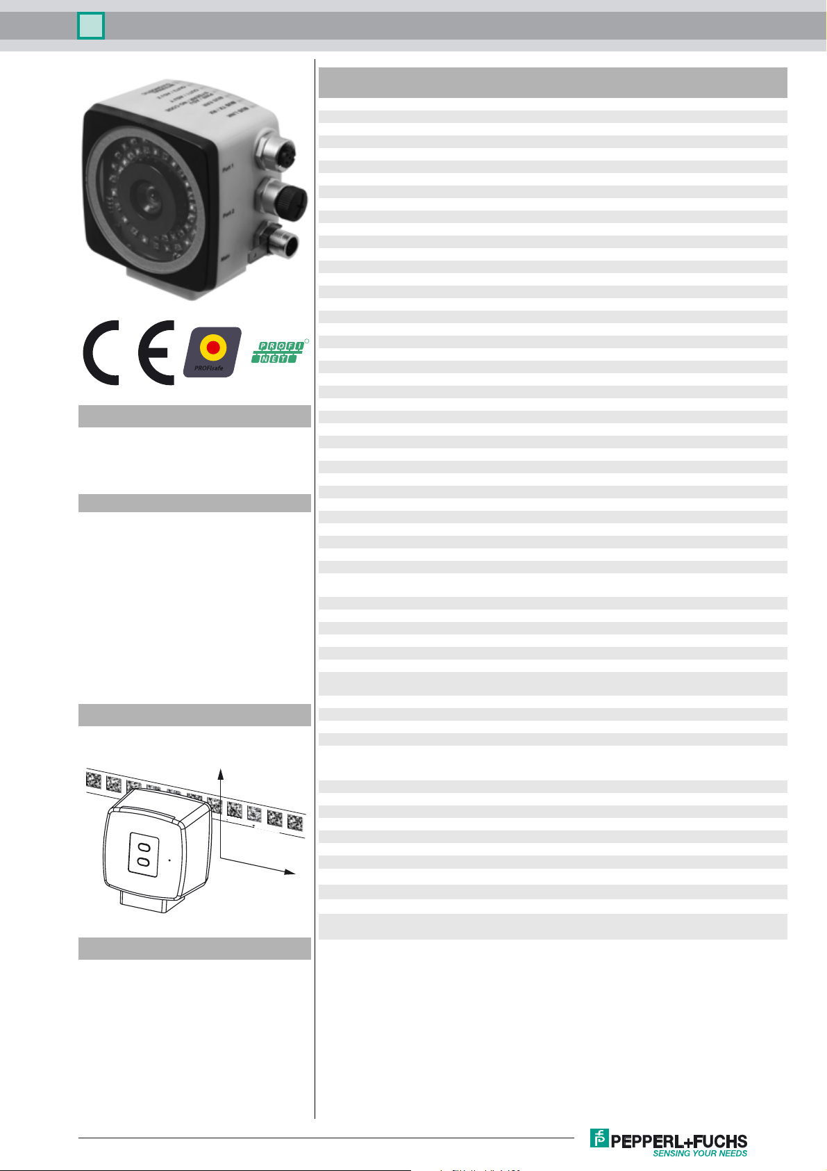
Optical reader - safePXV PXV100A-F200-B28-V1D
Technical data
General specifications
Passage speed v ≤ 8 m/s
Measuring range max. 100000 m
Light type Integrated LED lightning (red/blue)
Read distance 100 mm
Depth of focus ± 30 mm
Field of view typ. 120 mm x 80 mm
Ambient light limit 30000 Lux
Accuracy
Non safety-related X ± 0.2 mm
Safety-related X See the original instructions
Nominal ratings
Camera
Type CMOS , Global shutter
Processor
Clock pulse frequency 600 MHz
Speed of computation 4800 MIPS
Functional safety related parameters
Safety Integrity Level (SIL) SIL 3
R
Performance level (PL) PL e
Category Cat. 4
Reaction time 165 ms
MTTF 41.66 a
MTTFd 104.74 a
Model number
PXV100A-F200-B28-V1D
Read head for incident light positioning
system
Features
• SIL 3 (EN 61508)
• Category 4 PL e (EN ISO 13849)
•PROFINET interface
• PROFIsafe interface
• Safe, non-contact positioning on Data
Matrix code tape
• Traverse distance up to 100 km
• Mechanically rugged: no wearing
parts, long operating life,
maintenance-free
Diagramms
Position Data
Y
000 009.0 m PXV-AA25
X
System components
PXV*-AA25-*
Data Matrix code tape
Mission Time (T
PFH 1.09 E-8 typ.
Indicators/operating means
LED indication 7 LEDs (communication, status messages)
Electrical specifications
Operating voltage U
No-load supply current I
Power consumption P
Interface
Interface type 100 BASE-TX
Protocol PROFINET IO Real-Time (RT) Conformance class B
Transfer rate 100 MBit/s
Conformity
Fieldbus standard PROFIsafe in accordance with IEC 61784-3-3; profile 2.4
Functional safety EN ISO 13849-1:2015 ; EN 61508:2010 part 1-7 ;
Shock resistance EN 60068-2-27:2009
Vibration resistance EN 60068-2-6:2008
Emitted interference EN 61000-6-4:2007+A1:2011
Noise immunity EN 61000-6-7:2015
Photobiological safety risk group 2 according IEC 62471
Ambient conditions
Operating temperature 0 ... 45 °C (32 ... 113 °F) , -20 ... 45 °C (-4 ... 113 °F)
Storage temperature -40 ... 85 °C (-40 ... 185 °F)
Relative humidity 90 % , noncondensing
Altitude ≤ 2000 m above MSL
Mechanical specifications
Connection type 8-pin, M12x1 connector, standard
Housing width 70 mm
Housing height 70 mm
Housing depth 50 mm
Degree of protection IP67
Material
Housing PC/ABS
Mass approx. 200 g
Approvals and certificates
CE conformity CE
CCC approval CCC approval / marking not required for products rated ≤36
TÜV approval TÜV Rheinland 01/205/5669.00/18
) 20 a
M
B
0
0
20 ... 30 V DC , PELV
max. 300 mA
6 W
EN 62061:2005 + AC:2010 + A1:2013 + A2:2015
(noncondensing; prevent icing on the lens!)
4-pin, M12x1 socket, D-coded (LAN)
4-pin, M12x1 socket, D-coded (LAN)
V
Release date: 2019-02-26 16:34 Date of issue: 2019-02-26 296169_eng.xml
Refer to “General Notes Relating to Pepperl+Fuchs Product Information”.
Pepperl+Fuchs Group
1
PXV100A-F200-B28-V1DOptical reader - safePXV
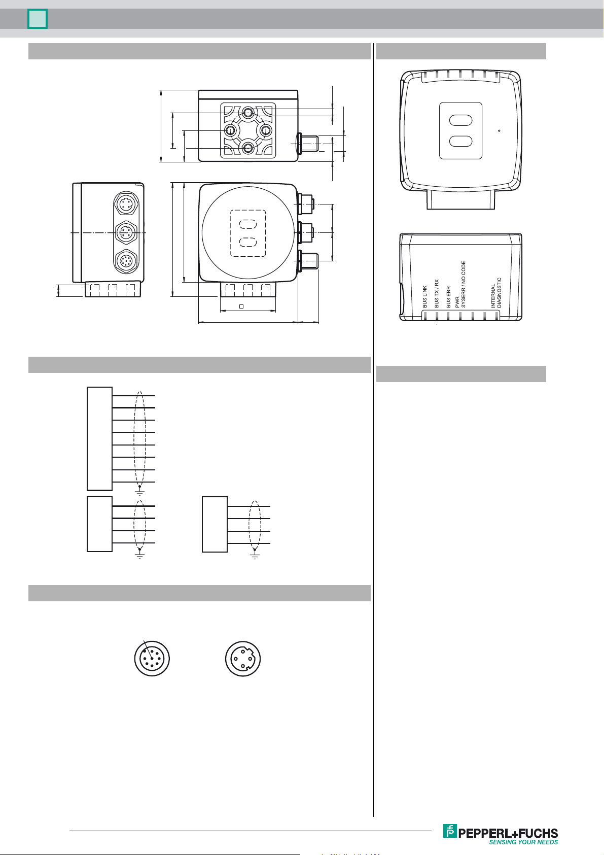
Dimensions
9
Additional information
4 x M6
50
ø 25
22
1
70
80
2
38.5
70 14.5
M12 x 1
12.5
20 20
SERVICE
NO FUNCTION
LED 1 2 3 4 5 6 7
1
2
Electrical connection
1
2
3
4
5
Main
6
7
8
1
2
3
Bus
4
Pinout
2
Accessories
n.c.
+ UB
n.c.
n.c.
n.c.
n.c.
GND
n.c.
Bus
1
2
3
4
TX +
RX +
TX -
RX -
TX +
RX +
TX -
RX -
Profinet 1 & 2Main
1
8
7
6
53
4
1
4
2
3
PGV25M-CD100-CLEAR
Protective laminate for PGV code tape
PCV-AG100
Alignment guide for PCV100-* read head
PCV-SC12
Grounding clip for PCV system
PCV-SC12A
Grounding clip for PCV system
PCV-LM25
Marker head for 25 mm code tape
PCV-MB1
Mounting bracket for PCV* read head
V1SD-G-2M-PUR-ABG-V1SD-G
Ethernet bus cable, M12 to M12, PUR
cable 4-pin, CAT5e
V1SD-G-5M-PUR-ABG-V1SD-G
Ethernet bus cable, M12 to M12, PUR
cable 4-pin, CAT5e
V1SD-G-10M-PUR-ABG-V1SD-G
Ethernet bus cable, M12 to M12, PUR
cable 4-pin, CAT5e
V1SD-G-5M-PUR-ABG-V45-G
Connection cable, M12 to RJ-45, PUR
cable 4-pin, CAT5e
V1SD-G-10M-PUR-ABG-V45-G
Connection cable, M12 to RJ-45, PUR
cable 4-pin, CAT5e
V1SD-G-30M-PUR-ABG-V45-G
Connection cable, M12 to RJ-45, PUR
cable 4-pin, CAT5e
V19-G-ABG-PG9
Release date: 2019-02-26 16:34 Date of issue: 2019-02-26 296169_eng.xml
Refer to “General Notes Relating to Pepperl+Fuchs Product Information”.
2
Pepperl+Fuchs Group

Optical reader - safePXV PXV100A-F200-B28-V1D
Accessories
Female connector, M12, 8-pin, shielded,
field attachable
V19-G-ABG-PG9-FE
Female connector, M12, 8-pin, shielded,
field attachable
V19-G-2M-PUR-ABG
Female cordset, M12, 8-pin, shielded,
PUR cable
V19-G-5M-PUR-ABG
Female cordset, M12, 8-pin, shielded,
PUR cable
V19-G-10M-PUR-ABG
Female cordset, M12, 8-pin, shielded,
PUR cable
Additional Information
Function
The reader forms part of the positioning system in the Pepperl+Fuchs incident light
process. The reader's features include a camera module and internal illumination
unit, enabling it to detect position markers printed onto an adhesive, colored code
tape in the form of Data Matrix codes. The code tape is generally mounted
stationary on a fixed part of the plant, e.g., elevator shaft, monorail conveyor
mounting rails, etc., and the reader is mounted parallel on the moving "vehicle," e.g.,
elevator car, monorail conveyor chassis, etc.
The positioning system issues position values that achieve the reliability required by
SIL 3 and PL e, provided that the device is properly integrated into the plant
according to the specifications given in the original instructions.
Mounting and Commissioning
Mount the reader such that the optical surface of the device captures the optimal
reading distance to the Data Matrix code tape (see "Technical Data"). The stability
of the mounting and the manner in which the vehicle is guided ensure that the reader
is not operated outside of its depth of focus range. The code tape must not leave the
maximum reading window for the reader during this process.
Displays and Operating Elements
The reader is equipped with the following indicator LEDs for carrying out visual
function checks and quick diagnostics:
LEDs
LED Color
1 Green BUS LINK PROFINET connection activated
2 Yellow BUS TX/RX Data transfer
3 Red BUS ERR PROFINET communication error
4 Red/green PWR
5 - – No function
6 - – No function
7 Red/green/
yellow
Label Meaning
SYSERR/NO
CODE
INTERNAL
DIAGNOSTIC
Code detected/not detected, error
Internal diagnostics
The SERVICE button on the back of the device is used for internal service purposes.
Release date: 2019-02-26 16:34 Date of issue: 2019-02-26 296169_eng.xml
Refer to “General Notes Relating to Pepperl+Fuchs Product Information”.
Pepperl+Fuchs Group
3
 Loading...