

Page 1

ISO9001
3
PROCESS AUTOMATION
MANUAL
Pulscon LTC57
PROFIBUS PA
Guided Level Radar
Level measurement in bulk solids
Page 2

Pulscon LTC57 PROFIBUS PA
With regard to the supply of products, the current issue of the following document is applicable:
The General Terms of Delivery for Products and Services of the Electrical Industry,
published by the Central Association of the Electrical Industry (Zentralverband Elektrotechnik und
Elektroindustrie (ZVEI) e.V.) in its most recent version as well as the supplementary clause:
"Expanded reservation of proprietorship"
Page 3

Pulscon LTC57 PROFIBUS PA
Content
1 Important document information . . . . . . . . . . . . . . . . . . . . . . . . . . . . . . . . . . 6
1.1 Document function . . . . . . . . . . . . . . . . . . . . . . . . . . . . . . . . . . . . . . . . . . 6
1.2 Symbols . . . . . . . . . . . . . . . . . . . . . . . . . . . . . . . . . . . . . . . . . . . . . . . . . . . 6
1.3 Supplementary documentation . . . . . . . . . . . . . . . . . . . . . . . . . . . . . . . 9
2 Basic safety instructions . . . . . . . . . . . . . . . . . . . . . . . . . . . . . . . . . . . . . . . 11
2.1 Requirements for the personnel . . . . . . . . . . . . . . . . . . . . . . . . . . . . . . 11
2.2 Designated use . . . . . . . . . . . . . . . . . . . . . . . . . . . . . . . . . . . . . . . . . . . . 11
2.3 Workplace safety . . . . . . . . . . . . . . . . . . . . . . . . . . . . . . . . . . . . . . . . . . . 12
2.4 Operational safety . . . . . . . . . . . . . . . . . . . . . . . . . . . . . . . . . . . . . . . . . . 12
2.5 Product safety . . . . . . . . . . . . . . . . . . . . . . . . . . . . . . . . . . . . . . . . . . . . . 12
3 Product description . . . . . . . . . . . . . . . . . . . . . . . . . . . . . . . . . . . . . . . . . . . . 13
3.1 Design . . . . . . . . . . . . . . . . . . . . . . . . . . . . . . . . . . . . . . . . . . . . . . . . . . . . 13
3.2 Registered trademarks . . . . . . . . . . . . . . . . . . . . . . . . . . . . . . . . . . . . . 15
4 Incoming acceptance and product identification . . . . . . . . . . . . . . . . . . . 16
4.1 Incoming acceptance . . . . . . . . . . . . . . . . . . . . . . . . . . . . . . . . . . . . . . . 16
4.2 Product identification . . . . . . . . . . . . . . . . . . . . . . . . . . . . . . . . . . . . . . . 17
5 Storage, Transport. . . . . . . . . . . . . . . . . . . . . . . . . . . . . . . . . . . . . . . . . . . . . 19
5.1 Storage conditions . . . . . . . . . . . . . . . . . . . . . . . . . . . . . . . . . . . . . . . . . 19
5.2 Transport product to the measuring point . . . . . . . . . . . . . . . . . . . . . . 19
6 Mounting . . . . . . . . . . . . . . . . . . . . . . . . . . . . . . . . . . . . . . . . . . . . . . . . . . . . . 20
6.1 Mounting requirements . . . . . . . . . . . . . . . . . . . . . . . . . . . . . . . . . . . . . 20
6.2 Mounting the device . . . . . . . . . . . . . . . . . . . . . . . . . . . . . . . . . . . . . . . . 34
6.3 Post-installation check . . . . . . . . . . . . . . . . . . . . . . . . . . . . . . . . . . . . . 41
7 Electrical connection. . . . . . . . . . . . . . . . . . . . . . . . . . . . . . . . . . . . . . . . . . . 42
7.1 Connection conditions . . . . . . . . . . . . . . . . . . . . . . . . . . . . . . . . . . . . . . 42
7.2 Connecting the device . . . . . . . . . . . . . . . . . . . . . . . . . . . . . . . . . . . . . . 46
7.3 Post-connection check . . . . . . . . . . . . . . . . . . . . . . . . . . . . . . . . . . . . . 48
2015-03
3
Page 4

Pulscon LTC57 PROFIBUS PA
Content
8 Operating options . . . . . . . . . . . . . . . . . . . . . . . . . . . . . . . . . . . . . . . . . . . . . 49
8.1 Overview. . . . . . . . . . . . . . . . . . . . . . . . . . . . . . . . . . . . . . . . . . . . . . . . . . 49
8.2 Structure and function of the operating menu . . . . . . . . . . . . . . . . . . 51
8.3 Display and operating module . . . . . . . . . . . . . . . . . . . . . . . . . . . . . . . 57
9 Integration into a PROFIBUS network. . . . . . . . . . . . . . . . . . . . . . . . . . . . . 65
9.1 Overview of the device database files (GSD) . . . . . . . . . . . . . . . . . . . 65
9.2 Set device address . . . . . . . . . . . . . . . . . . . . . . . . . . . . . . . . . . . . . . . . . 65
10 Commissioning (via operating menu) . . . . . . . . . . . . . . . . . . . . . . . . . . . . 67
10.1 Installation and function check . . . . . . . . . . . . . . . . . . . . . . . . . . . . . . . 67
10.2 Setting the operating language. . . . . . . . . . . . . . . . . . . . . . . . . . . . . . . 67
10.3 Configuration of a level measurement . . . . . . . . . . . . . . . . . . . . . . . . 68
10.4 Recording the reference curve . . . . . . . . . . . . . . . . . . . . . . . . . . . . . . . 69
10.5 Configuration of the on-site display . . . . . . . . . . . . . . . . . . . . . . . . . . 70
10.6 Configuration management . . . . . . . . . . . . . . . . . . . . . . . . . . . . . . . . . 71
10.7 Protection of the settings against unauthorized changes. . . . . . . . . 71
11 Diagnostics and troubleshooting . . . . . . . . . . . . . . . . . . . . . . . . . . . . . . . . 72
11.1 General trouble shooting . . . . . . . . . . . . . . . . . . . . . . . . . . . . . . . . . . . . 72
11.2 Diagnostic information on local display . . . . . . . . . . . . . . . . . . . . . . . 74
11.3 Diagnostic event in the operating tool . . . . . . . . . . . . . . . . . . . . . . . . . 77
11.4 Diagnostic list . . . . . . . . . . . . . . . . . . . . . . . . . . . . . . . . . . . . . . . . . . . . . 78
11.5 List of diagnostic events . . . . . . . . . . . . . . . . . . . . . . . . . . . . . . . . . . . . 78
11.6 Event logbook . . . . . . . . . . . . . . . . . . . . . . . . . . . . . . . . . . . . . . . . . . . . . 81
11.7 Firmware history . . . . . . . . . . . . . . . . . . . . . . . . . . . . . . . . . . . . . . . . . . . 83
12 Maintenance . . . . . . . . . . . . . . . . . . . . . . . . . . . . . . . . . . . . . . . . . . . . . . . . . . 84
12.1 Exterior cleaning . . . . . . . . . . . . . . . . . . . . . . . . . . . . . . . . . . . . . . . . . . . 84
4
2015-03
Page 5

Pulscon LTC57 PROFIBUS PA
Content
13 Repairs . . . . . . . . . . . . . . . . . . . . . . . . . . . . . . . . . . . . . . . . . . . . . . . . . . . . . . 85
13.1 General information on repairs . . . . . . . . . . . . . . . . . . . . . . . . . . . . . . . 85
13.2 Spare parts . . . . . . . . . . . . . . . . . . . . . . . . . . . . . . . . . . . . . . . . . . . . . . . 86
13.3 Return . . . . . . . . . . . . . . . . . . . . . . . . . . . . . . . . . . . . . . . . . . . . . . . . . . . . 86
13.4 Disposal . . . . . . . . . . . . . . . . . . . . . . . . . . . . . . . . . . . . . . . . . . . . . . . . . . 86
14 Accessories . . . . . . . . . . . . . . . . . . . . . . . . . . . . . . . . . . . . . . . . . . . . . . . . . . 87
14.1 Device-specific accessories . . . . . . . . . . . . . . . . . . . . . . . . . . . . . . . . . 87
14.2 Communication-specific accessories . . . . . . . . . . . . . . . . . . . . . . . . . 90
14.3 Service-specific accessories . . . . . . . . . . . . . . . . . . . . . . . . . . . . . . . . . 90
14.4 System components . . . . . . . . . . . . . . . . . . . . . . . . . . . . . . . . . . . . . . . . 90
15 Operating menu . . . . . . . . . . . . . . . . . . . . . . . . . . . . . . . . . . . . . . . . . . . . . . . 91
15.1 Overview of the operating menu (display module). . . . . . . . . . . . . . . 91
15.2 Overview of the operating menu (operating tool) . . . . . . . . . . . . . . . 96
15.3 Setup menu . . . . . . . . . . . . . . . . . . . . . . . . . . . . . . . . . . . . . . . . . . . . . . 101
15.4 Diagnostics menu . . . . . . . . . . . . . . . . . . . . . . . . . . . . . . . . . . . . . . . . . 149
Index . . . . . . . . . . . . . . . . . . . . . . . . . . . . . . . . . . . . . . . . . . . . . . . . . . . . . . . . . . . 166
2015-03
5
Page 6
Pulscon LTC57 PROFIBUS PA
Important document information
1 Important document information
1.1 Document function
These Operating Instructions contain all the information that is required in various phases of
the life cycle of the device: from product identification, incoming acceptance and storage, to
mounting, connection, operation and commissioning through to troubleshooting, maintenance
and disposal.
1.2 Symbols
1.2.1 Symbols used
This document contains information that you must read for your own personal safety and to
avoid property damage. Depending on the risk level, the warning messages are displayed in
descending order as follows:
Safety-relevant symbols
Danger!
This symbol indicates an imminent danger.
Non-observance will result in personal injury or death.
Warning!
This symbol indicates a possible fault or danger.
Non-observance may cause personal injury or serious property damage.
Caution!
This symbol indicates a possible fault.
Non-observance could interrupt the device and any connected systems and plants, or result in
their complete failure.
Informative symbols
Note!
This symbol brings important information to your attention.
Action
This symbol indicates a paragraph with instructions.
2015-03
6
Page 7
Pulscon LTC57 PROFIBUS PA
)
*
Important document information
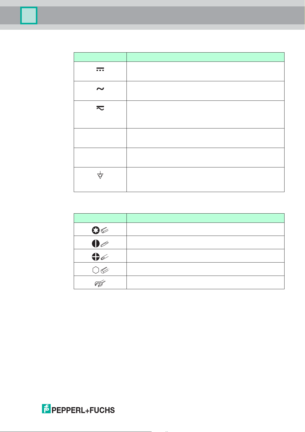
1.2.2 Electrical symbols
Symbol Meaning
Table 1.1
Direct current
A terminal to which DC voltage is applied or through which direct
current flows.
Alternating current
A terminal to which alternating voltage is applied or through which
alternating current flows.
Direct current and alternating current
• A terminal to which alternating voltage or DC voltage is applied.
• A terminal through which alternating current or direct current
flows.
Ground connection
A grounded terminal which, as far as the operator is concerned, is
grounded via a grounding system.
Protective ground connection
A terminal which must be connected to ground prior to establishing
any other connections.
Equipotential connection
A connection that has to be connected to the plant grounding
system: This may be a potential equalization line or a star grounding
system depending on national or company codes of practice.
1.2.3 Tool symbols
Symbol Meaning
Table 1.2
Torx screwdriver
Flat blade screwdriver
Cross-head screwdriver
Allen key
Hexagon wrench
2015-03
7
Page 8
Pulscon LTC57 PROFIBUS PA
Important document information
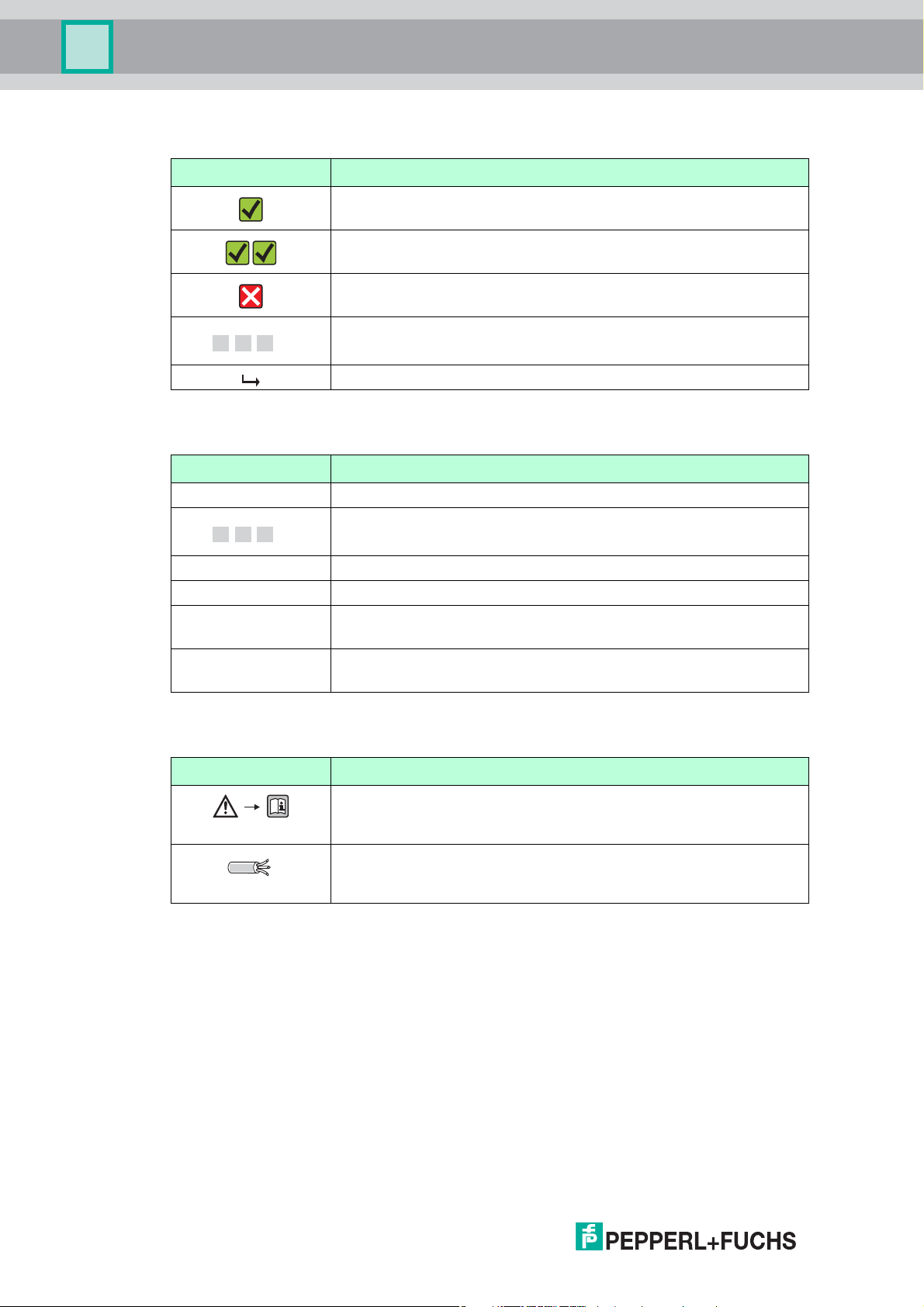
1.2.4 Symbols for certain types of information
Symbol Meaning
Allowed
Indicates procedures, processes or actions that are allowed.
Preferred
Indicates procedures, processes or actions that are preferred.
Forbidden
Indicates procedures, processes or actions that are forbidden.
,…,1. 2. 3.
Table 1.3
1.2.5 Symbols in graphics
Symbol Meaning
Series of steps
Result of a sequence of actions
1, 2, 3 ... Item numbers
,…,1. 2. 3.
A, B, C, ... Views
A-A, B-B, C-C, ... Sections
-
.
Table 1.4
Series of steps
Hazardous area
Indicates a hazardous area.
Safe area (non-hazardous area)
Indicates a non-hazardous location.
1.2.6 Symbols at the device
Symbol Meaning
Safety instructions
Observe the safety instructions contained in the associated
Operating Instructions.
Temperature resistance of the connection cables
Specifies the minimum value of the temperature resistance of the
connection cables.
Table 1.5
2015-03
8
Page 9
Pulscon LTC57 PROFIBUS PA
Important document information
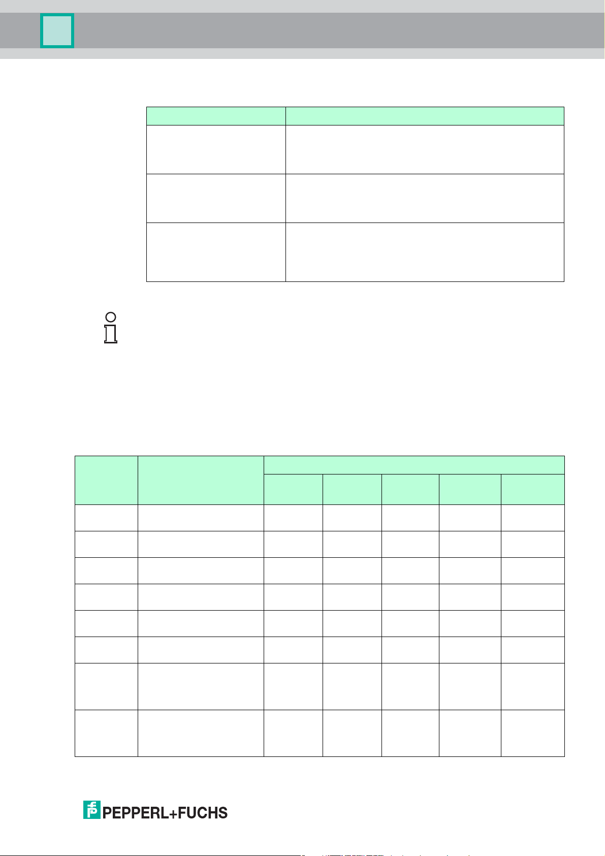
1.3 Supplementary documentation
Document Purpose and content of the document
Technical Information
TI01004O (LTC57)
Brief Operating Instructions
KA01073O (LTC57,
PROFIBUS PA)
Description of Device
Parameters
GP01001O (LTC5X,
PROFIBUS PA)
Table 1.6
Note!
For an overview of the scope of the associated Technical Documentation, refer to
www.pepperl-fuchs.com.
1.3.1 Safety documentation
Depending on the approval, the following Safety instructions (SI) are supplied with the device.
They are an integral part of the Operating instructions.
Planning aid for your device
The document contains all the technical data on the device
and provides an overview of the accessories and other
products that can be ordered for the device.
Guide that takes you quickly to the 1st measured value
The Brief Operating Instructions contain all the essential
information from incoming acceptance to initial
commissioning.
Reference for your parameters
The document provides a detailed explanation of each
individual parameter in the operating menu. The description
is aimed at those who work with the device over the entire life
cycle and perform specific configurations.
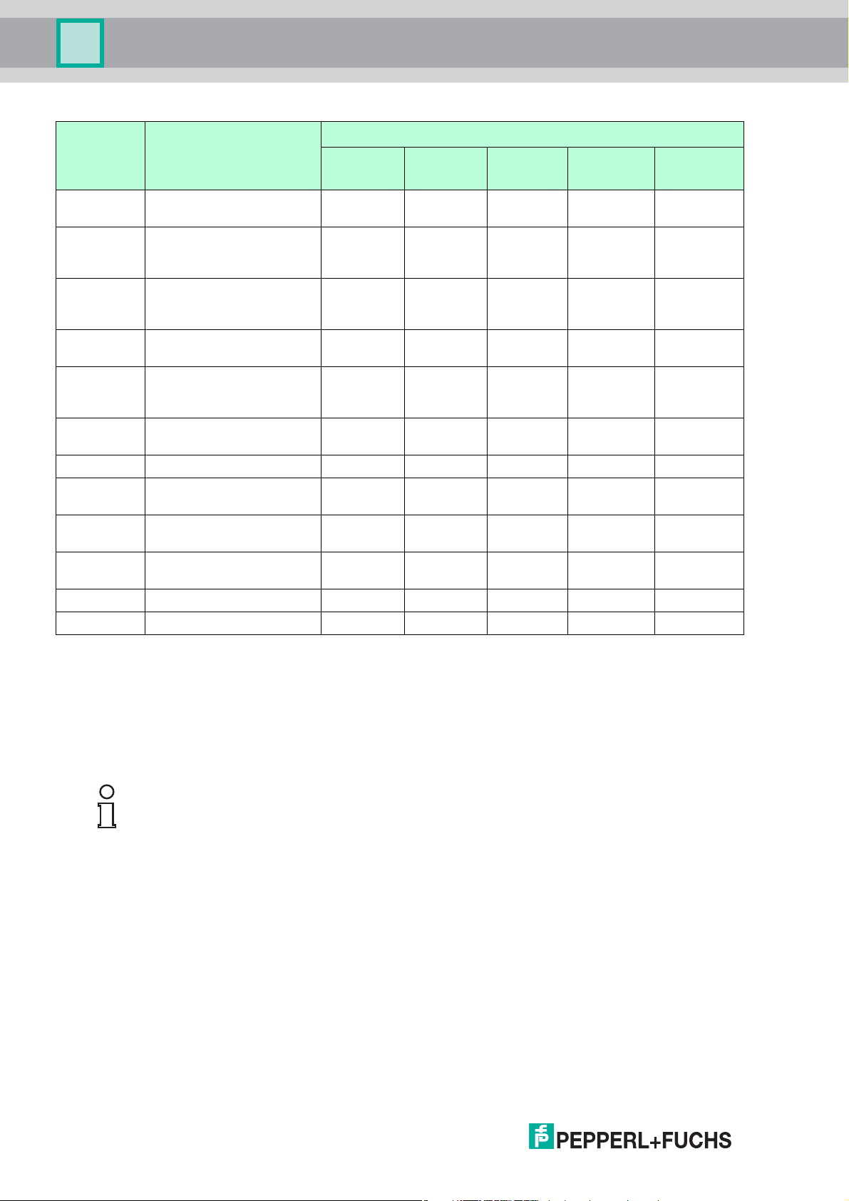
Safety instructions (SI)
Feature
"Approval"
E1 ATEX II 1G Ex ia IIC T6-
EX ATEX II 1/2G Ex ia IIC T6-
S3 ATEX II 1D Ex ta IIIC
S4 ATEX II 1/2D Ex ta IIIC
E3 ATEX II 3G Ex nA IIC T6-
E4 ATEX II 3G Ex ic IIC T6-T1 GcSI00498O SI01130O SI01131O SI00518O –
SX ATEX II 1/2G Ex ia IIC T6-
EG ATEX II 1/2G Ex d [ia] IIC
Approval Feature "Electrical output"
Option IHa Option IDb Option IEc Option PAd Option AH
T1 Ga
T1 Ga/Gb
T
xx°C Da
500
Txx°C Da/Db
T1 Gc
T1 Ga/Gb
ATEX II 1/2D Ex ia IIIC
Txx°C Da/Db
T6-T1 Ga/Gb
ATEX II 1/2D Ex ta IIIC
Txx°C Da/Db
SI00496O SI01125O SI01126O SI00516O –
SI00496O SI01125O SI01126O SI00516O –
SI00501O SI00501O SI00501O SI00521O SI00501O
SI00501O SI00501O SI00501O SI00521O SI00501O
SI00498O SI01130O SI01131O SI00518O SI01132O
SI00502O SI00502O SI00502O SI00522O –
SI00503O SI00503O SI00503O SI00523O SI01136O
Option DH
e
f
2015-03
9
Page 10
Pulscon LTC57 PROFIBUS PA
Important document information
Feature
"Approval"
Approval Feature "Electrical output"
Option IHa Option IDb Option IEc Option PAd Option AH
Option DH
CD CSA C/US DIP Cl.II,III
SI00529O SI00529O SI00529O SI00570O SI00529O
Div.1 Gr.E-G
C1 CSA C/US IS Cl.I,II,III
SI00530O SI00530O SI00530O SI00571O SI00530O
Div.1 Gr.A-G, NI Cl.1
Div.2, Ex ia
C2 CSA C/US XP Cl.I,II,III
SI00529O SI00529O SI00529O SI00570O SI00529O
Div.1 Gr.A-G, NI Cl.1
Div.2, Ex d
FI FM IS Cl.I,II,III Div.1 Gr.A-
SI00531O SI00531O SI00531O SI00573O SI00531O
G, AEx ia, NI Cl.1 Div.2
FN FM XP Cl.I,II,III Div.1
SI00532O SI00532O SI00532O SI00572O SI00532O
Gr.A-G, AEx d, NI Cl.1
Div.2
FE FM DIP Cl.II,III Div.1 Gr.E-GSI00532O SI00532O SI00532O SI00572O SI00532O
IA IECEx Ex ia IIC T6-T1 Ga SI00496O SI01125O SI01126O SI00516O –
IB IECEx Ex ia IIC T6-T1
SI00496O SI01125O SI01126O SI00516O –
Ga/Gb
IE IECEx Ex ta IIIC T
Da
IF IECEx Ex ta IIIC Txx°C
500
xx°C
SI00501O SI00501O SI00501O SI00521O SI00501O
SI00501O SI00501O SI00501O SI00521O SI00501O
Da/Db
IG IECEx Ex nA IIC T6-T1 Gc SI00498O SI01130O SI01131O SI00518O SI01132O
IH IECEx Ex ic IIC T6-T1 Gc SI00498O SI01130O SI01131O SI00518O –
Table 1.7
e
f
a
Option IH: 2-wire, 4 ... 20 mA, HART
b
Option ID: 2-wire, 4 ... 20 mA, HART, switching output
c
Option IE: 2-wire, 4 ... 20 mA, HART, 4 ... 20 mA
d
Option PA: 2-wire, PROFIBUS PA, switching output
e
Option AH: 4-wire, 90 ... 253 V AC, 4 ... 20 mA, HART
f
Option DH: 4-wire, 10.4 ... 48 V DC, 4 ... 20 mA, HART
Note!
For certified devices the relevant Safety instructions (SI) are indicated on the nameplate.
10
2015-03
Page 11

Pulscon LTC57 PROFIBUS PA
Basic safety instructions
2 Basic safety instructions
2.1 Requirements for the personnel
The personnel for installation, commissioning, diagnostics and maintenance must fulfill the
following requirements:
• Trained, qualified specialists must have a relevant qualification for this specific function
and task
• Are authorized by the plant owner/operator
• Are familiar with federal/national regulations
• Before beginning work, the specialist staff must have read and understood the instructions
in the Operating Instructions and supplementary documentation as well as in the
certificates (depending on the application)
• Following instructions and basic conditions
The operating personnel must fulfill the following requirements:
• Being instructed and authorized according to the requirements of the task by the facility's
owner-operator
• Following the instructions in these Operating Instructions
2.2 Designated use
Application and measured materials
The measuring device described in these Operating Instructions is intended only for level
measurement of bulk solids. Depending on the version ordered the device can also measure
potentially explosive, flammable, poisonous and oxidizing materials.
Observing the limit values specified in the "Technical data" and listed in the Operating
Instructions and supplementary documentation, the measuring device may be used for the
following measurements only:
• Measured process variable: Level
• Calculated process variables: Volume or mass in arbitrarily shaped vessels (calculated
from the level by the linearization functionality)
To ensure that the measuring device remains in proper condition for the operation time:
• Use the measuring device only for measured materials against which the process-wetted
materials are adequately resistant.
• Observe the limit values in "Technical data".
Incorrect use
The manufacturer is not liable for damage caused by improper or non-designated use.
Verification for borderline cases:
• For special measured materials and cleaning agents, Pepperl+Fuchs is glad to provide
assistance in verifying the corrosion resistance of wetted materials, but does not accept
any warranty or liability.
2015-03
11
Page 12

Pulscon LTC57 PROFIBUS PA
Basic safety instructions
Residual risk
The electronics housing and its built-in components such as display module, main electronics
module and I/O electronics module may heat to 80 °C (176 °F) during operation through heat
transfer from the process as well as power dissipation within the electronics. During operation
the sensor may assume a temperature near the temperature of the measured material.
Danger of burns due to heated surfaces!
• For high process temperatures: Install protection against contact in order to prevent burns.
2.3 Workplace safety
For work on and with the device:
• Wear the required personal protective equipment according to federal/national regulations.
2.4 Operational safety
Risk of injury.
• Operate the device in proper technical condition and fail-safe condition only.
• The operator is responsible for interference-free operation of the device.
Conversions to the device
Unauthorized modifications to the device are not permitted and can lead to unforeseeable
dangers.
• If, despite this, modifications are required, consult with the manufacturer.
Repair
To ensure continued operational safety and reliability,
• Carry out repairs on the device only if they are expressly permitted.
• Observe federal/national regulations pertaining to repair of an electrical device.
• Use original spare parts and accessories from the manufacturer only.
Hazardous area
To eliminate a danger for persons or for the facility when the device is used in the hazardous
area (e. g. explosion protection, pressure vessel safety):
• Based on the nameplate, check whether the ordered device is permitted for the intended
use in the hazardous area.
• Observe the specifications in the separate supplementary documentation that is an
integral part of these Instructions.
2.5 Product safety
This measuring device is designed in accordance with good engineering practice to meet
state-of-the-art safety requirements, has been tested, and left the factory in a condition in
which they are safe to operate.
12
It meets general safety standards and legal requirements. It also complies with the
EC directives listed in the device-specific EC Declaration of Conformity. Pepperl+Fuchs
confirms this by affixing the CE mark to the device.
2015-03
Page 13
Pulscon LTC57 PROFIBUS PA
1
2
5
3
4
Product description
3 Product description
3.1 Design
3.1.1 Device
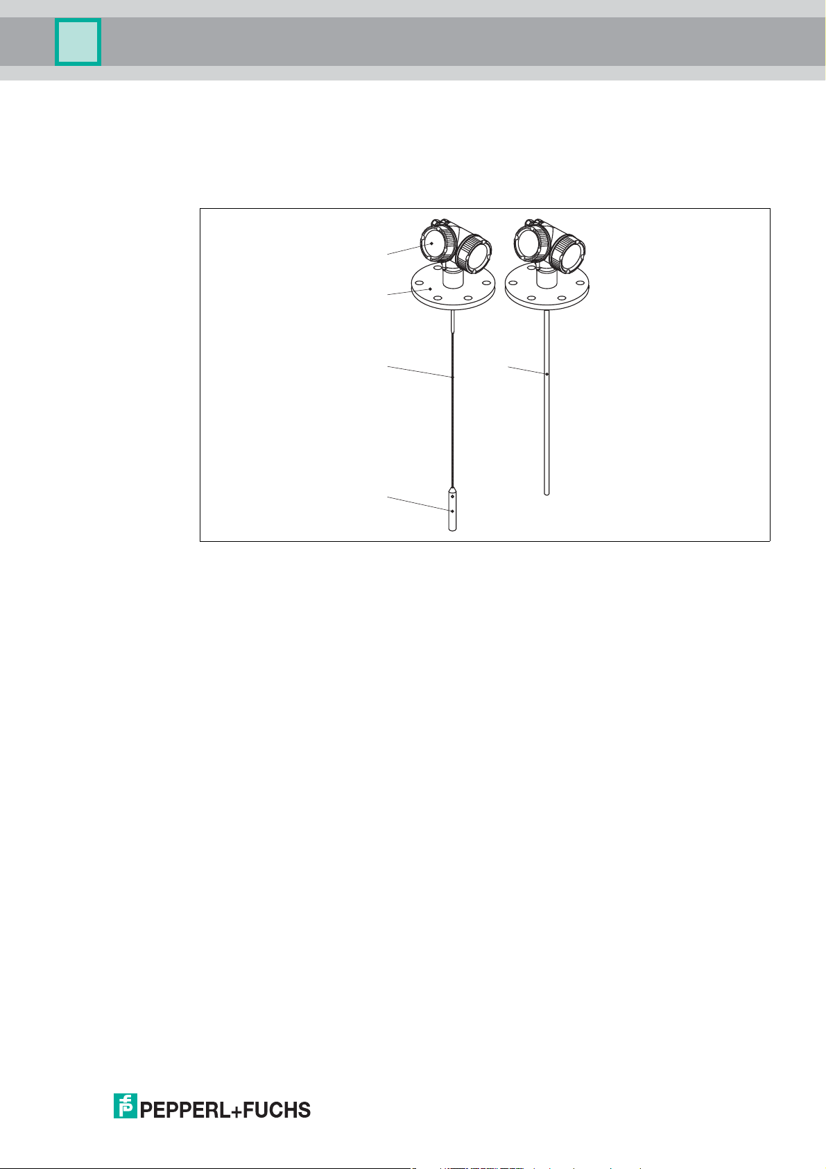
Figure 3.1 Design
1 Electronics housing
2 Process connection (here as an example: flange)
3 Rope probe
4 End-of-probe weight
5 Rod probe
2015-03
13
Page 14
Pulscon LTC57 PROFIBUS PA
E
s
c
–
+
E
1
2
3
4
5
6
9
7
8
Product description
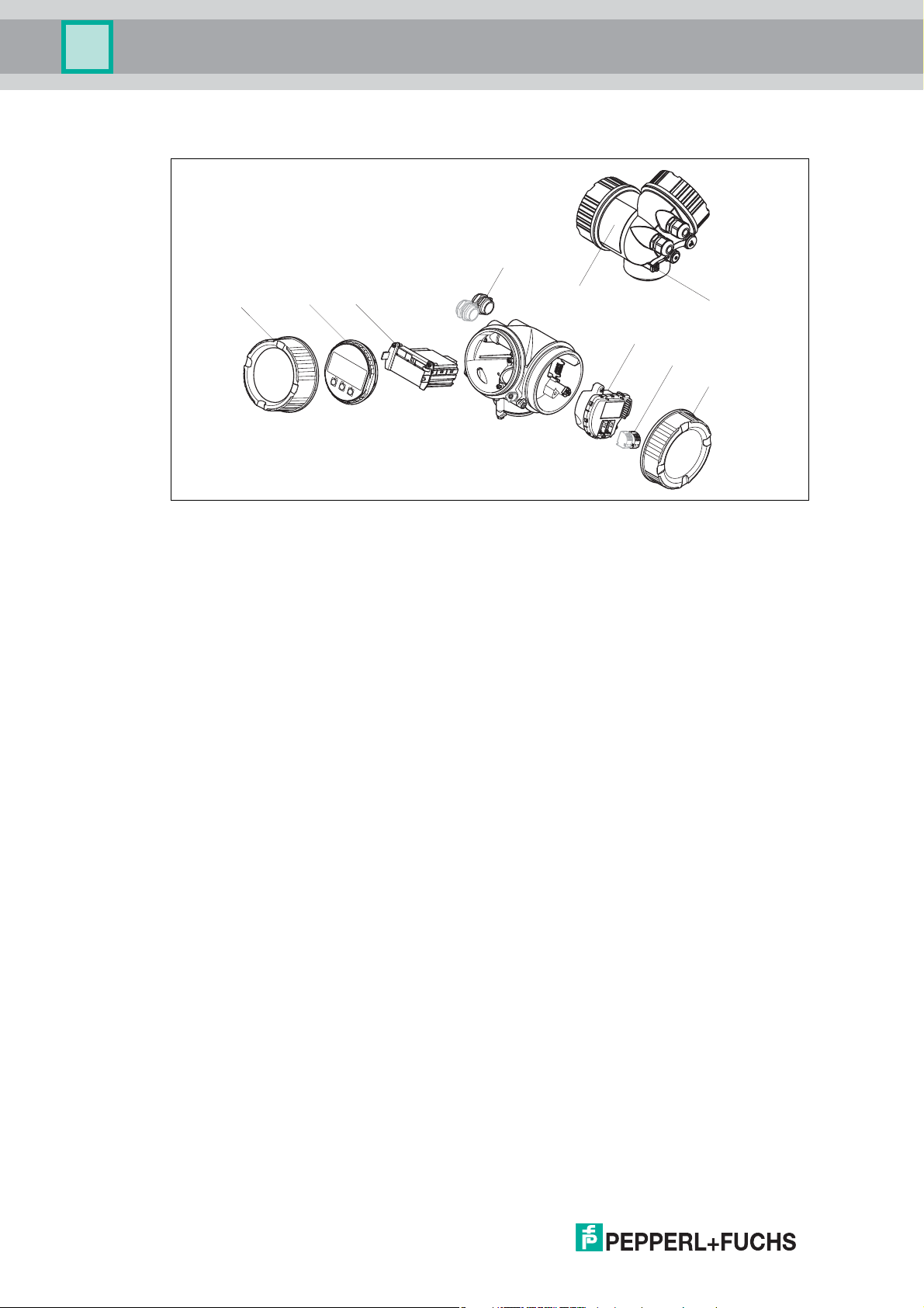
3.1.2 Electronics housing
Figure 3.2 Design of the electronics housing
1 Electronics compartment cover
2 Display module
3 Main electronics module
4 Cable glands (1 or 2, depending on instrument version)
5 Nameplate
6 I/O electronics module
7 Terminals (pluggable spring terminals)
8 Connection compartment cover
9 Grounding terminal
2015-03
14
Page 15

Pulscon LTC57 PROFIBUS PA
Product description
3.2 Registered trademarks
®
HART
• Registered trademark of the HART Communication Foundation, Austin, USA
PROFIBUS
• Registered trademark of the PROFIBUS User Organization, Karlsruhe, Germany
KALREZ
• Registered trademark of DuPont Performance Elastomers L.L.C., Wilmington, USA
TEFLON
• Registered trademark of E.I. DuPont de Nemours & Co., Wilmington, USA
TRI CLAMP
• Registered trademark of Alfa Laval Inc., Kenosha, USA
®
®
, VITON
®
®
®
2015-03
15
Page 16
Pulscon LTC57 PROFIBUS PA
DELIVERY NOTE
1 = 2
DELIVERYNOTE
Madein Germany
Incoming acceptance and product identification
4 Incoming acceptance and product identification
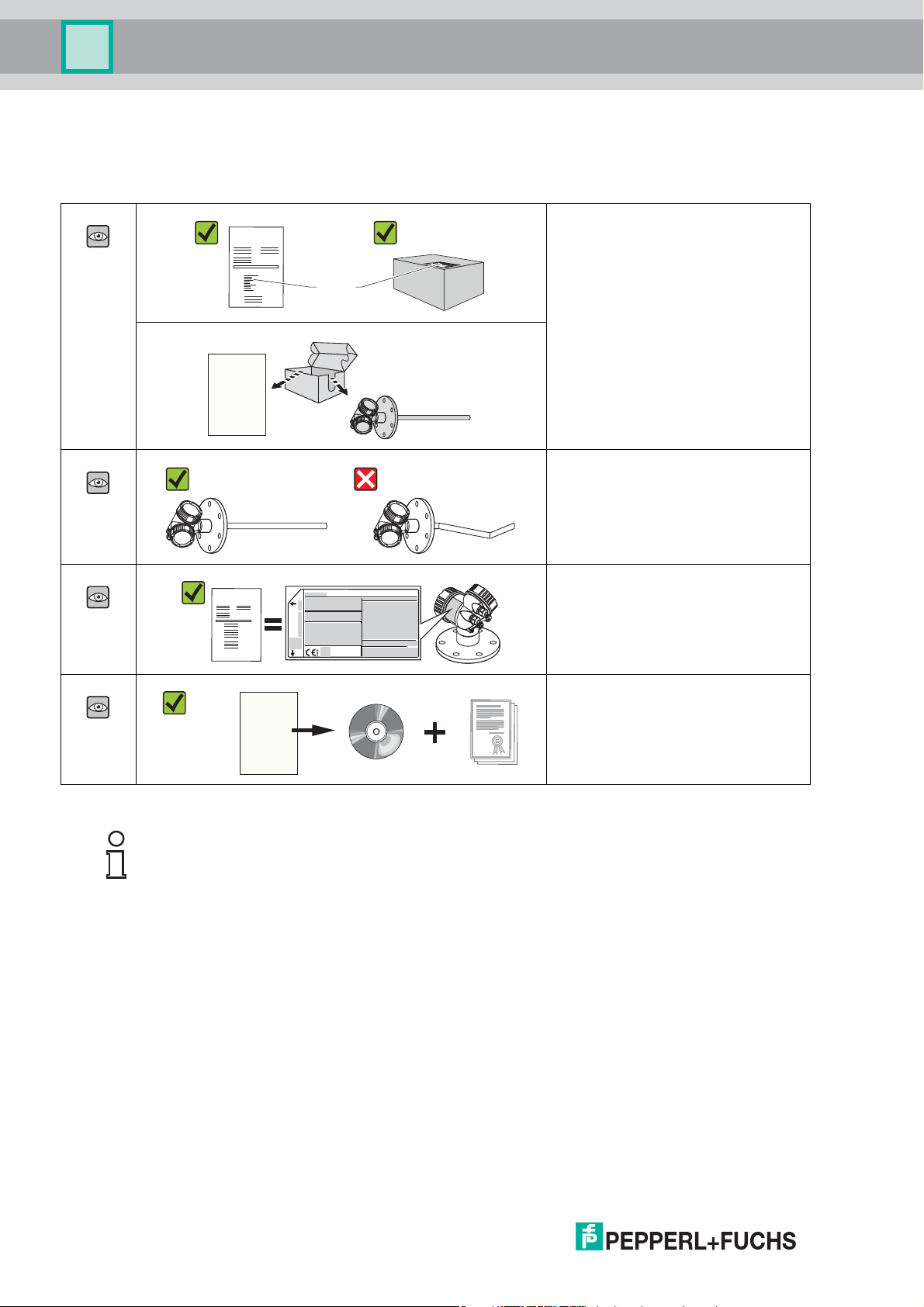
4.1 Incoming acceptance
Is the order code on the delivery note
(1) identical to the order code on the
product sticker (2)?
Are the goods undamaged?
Table 4.1
Do the nameplate data match the
ordering information on the delivery
note?
Is the DVD (operating tool) present?
If required (see nameplate): Are the
Safety Instructions (SI) present?
Note!
If one of the conditions does not comply, contact your Pepperl+Fuchs distributor.
16
2015-03
Page 17
Pulscon LTC57 PROFIBUS PA
20
21
22
24
25
23
26
1
2
3
4
5
6
7
8
9
10
19
18
17
16
15
14
Ext. ord. cd.:
Order code:
Ser. no.:
LN =
Lref =
Mat.:
Date:
FW:
Dev.Rev.:
DeviceID:
Ta :
if modification
see sep. label
X =
MWP:
12
11
47 (1.85)
92 (3.62)
mm (in)
13
Incoming acceptance and product identification
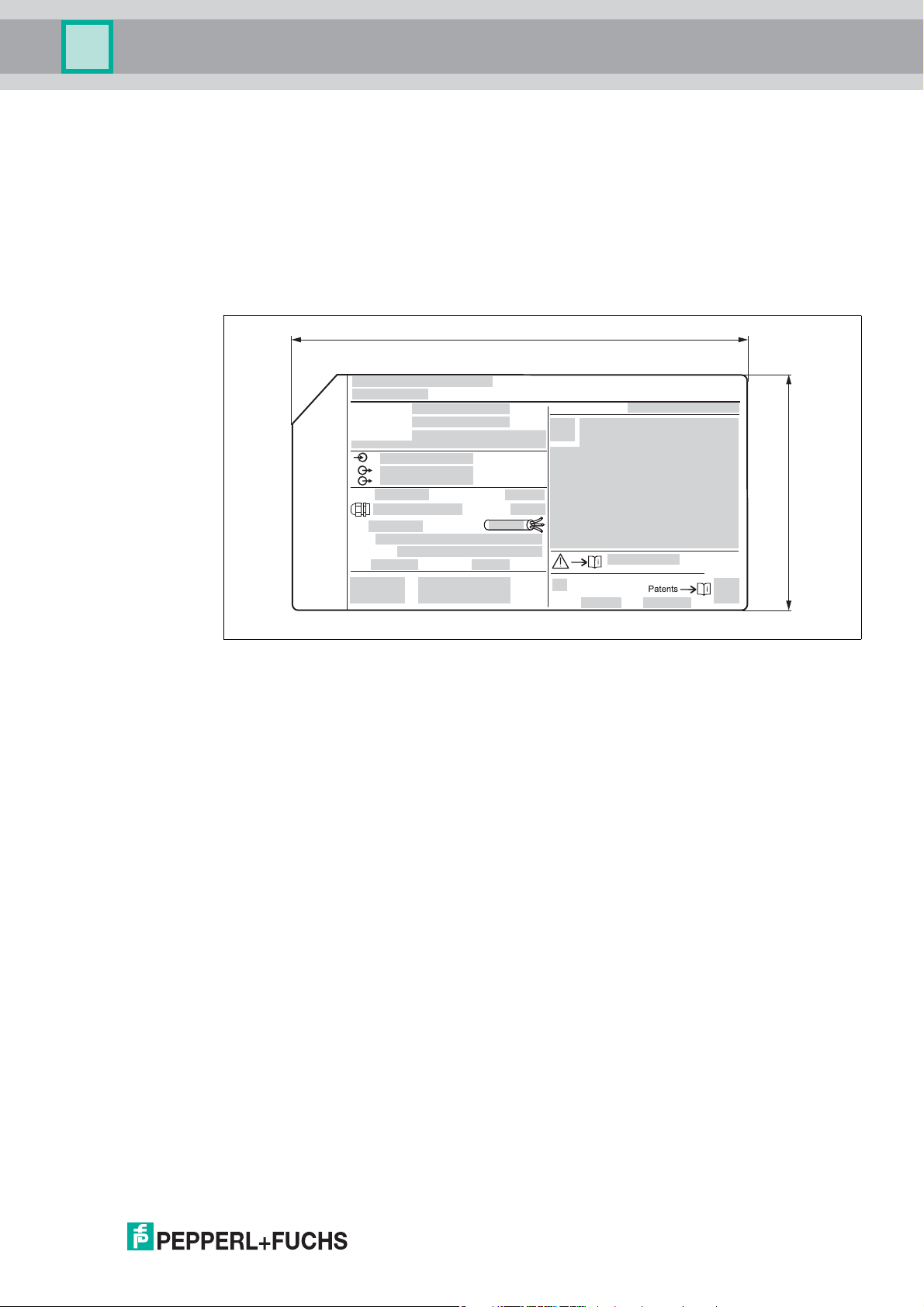
4.2 Product identification
The following options are available for identification of the measuring device:
• Nameplate specifications
• Order code with breakdown of the device features on the delivery note
• Scan the 2-D matrix code (QR code) on the nameplate: all the information for the
measuring device is displayed.
Nameplate
2015-03
Figure 4.1 Nameplate
1 Device name
2 Address of manufacturer
3 Order code
4 Serial number (Ser. no.)
5 Extended order code (Ext. ord. cd.)
6 Process pressure
7 Gas phase compensation: reference distance
8 Certificate symbol
9 Certificate and approval relevant data
10 Degree of protection: e. g. IP, NEMA
11 Document number of the Safety Instructions: e. g. SI, ZD, ZE
12 2-D matrix code (QR code)
13 Modification mark
14 Manufacturing date: year-month
15 Permitted temperature range for cable
16 Device revision (Dev.Rev.)
17 Additional information about the device version (certificates, approvals, communication):
e. g. SIL, PROFIBUS
18 Firmware version (FW)
19 CE mark, C-Tick
17
Page 18

Pulscon LTC57 PROFIBUS PA
Incoming acceptance and product identification
20 Device ID
21 Material in contact with process
22 Permitted ambient temperature (T
23 Size of the thread of the cable glands
24 Length of probe
25 Signal outputs
26 Operating voltage
Note!
Only 33 digits of the extended order code can be indicated on the nameplate. If the extended
order code exceeds 33 digits, the rest will not be shown. However, the complete extended
order code can be viewed in the operating menu of the device in the
Extended order code 1 to 3 parameter.
amb
)
18
2015-03
Page 19
Pulscon LTC57 PROFIBUS PA
Storage, Transport
5Storage, Transport
5.1 Storage conditions
• Permitted storage temperature: -40 ... +80 °C(-40...+176°F)
• Use the original packaging.
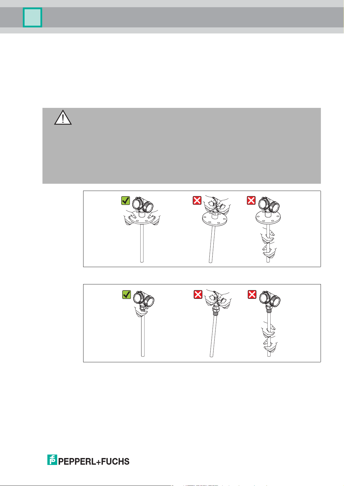
5.2 Transport product to the measuring point
Warning!
Risk of injury!
Housing or probe may be damaged or break away.
• Transport the measuring device to the measuring point in its original packaging or at the
process connection.
• Do not fasten lifting devices (hoisting slings, lifting eyes etc.) at the housing or the probe
but at the process connection. Take into account the mass center of the device in order to
avoid unintended tilting.
• Comply with the safety instructions, transport conditions for devices over 18 kg (39.6 lbs).
Figure 5.1
Figure 5.2
2015-03
19
Page 20
Pulscon LTC57 PROFIBUS PA
132
A
C
4
B
Mounting
6Mounting
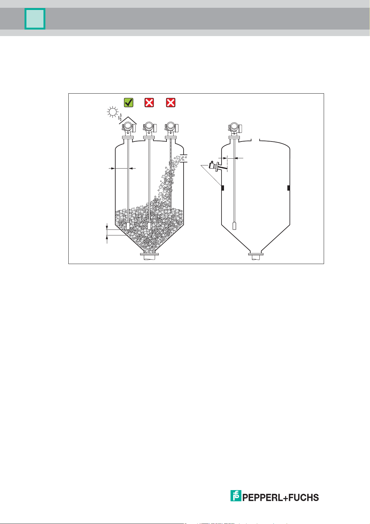
6.1 Mounting requirements
6.1.1 Suitable mounting position
Figure 6.1 Mounting requirements
Mounting distances
• Distance (A) between wall and rod or rope probe:
• for smooth metallic walls: > 50 mm (2 in)
• for plastic walls: > 300 mm (12 in) to metallic parts outside the vessel
• for concrete walls: > 500 mm (20 in), otherwise the available measuring range may be
reduced.
• Distance (B) between rod or rope probe and internal fittings in the vessel: > 300 mm (12 in)
• Distance (C) from end of probe to bottom of the vessel:
• Rope probe: > 150 mm (6 in)
•Rod probe: >10mm(0.4in)
2015-03
20
Page 21

Pulscon LTC57 PROFIBUS PA
Mounting
Additional conditions
• When mounting in the open, a weather protection cover (1) may be installed to protect the
device against extreme weather conditions.
• In metallic vessels: Preferably do not mount the probe in the center of the vessel (2), as this
would lead to increased interference echoes.
If a central mounting position can not be avoided, it is crucial to perform an interference
echo suppression (mapping) after the commissioning of the device.
• Do not mount the probe in the filling curtain (3).
• Avoid buckling the rope probe during installation or operation (e. g. through product
movement against silo wall) by selecting a suitable mounting location.
• Check the probe regularly for defects.
Note!
With suspended rope probes (probe end not fixed at the bottom) the distance between the
probe rope and internal fittings in the tank must not fall below 300 mm (12 in) during the entire
process. A sporadic contact between the probe weight and the cone of the vessel, however,
does not influence the measurement as long as the dielectric constant of the medium is at least
DC = 1.8.
Note!
When mounting the electronics housing into a recess (e. g. in a concrete ceiling), observe a
minimum distance of 100 mm (4 in) between the cover of the terminal compartment/electronics
compartment and the wall. Otherwise the connection compartment/electronics compartment is
not accessible after installation.
2015-03
21
Page 22
Pulscon LTC57 PROFIBUS PA
A
B
6 Nm
(4.42 lbf ft)
6 Nm
(4.42 lbf ft)
6 Nm
(4.42 lbf ft)
C
C
6 Nm
(4.42 lbf ft)
r = 100 (4)
min
r = 100 (4)
min
Mounting
6.1.2 Applications with restricted mounting space
Mounting with remote sensor
The device version with a remote sensor is suited for applications with restricted mounting
space. In this case the electronics housing is mounted at a separate position from which it is
easier accessible.
Figure 6.2
A Angled plug at the probe
B Angled plug at the electronics housing
C Length of the remote cable as ordered
• Product structure, feature "Probe design": option B "Sensor remote, 3 m/9 ft cable"
• The remote cable is supplied with these device versions, minimum bending radius:
100 mm (4 in)
• A mounting bracket for the electronics housing is supplied with these device versions.
Mounting options:
• Wall mounting
• Pipe mounting; diameter: 42 to 60 mm (1-1/4 to 2 in)
• The connection cable has got one straight and one angled plug (90°). Depending on the
local conditions the angled plug can be connected at the probe or at the electronics
housing.
Note!
Probe, electronics and connection cable are adjusted to match each other. They are marked
by a common serial number. Only components with the same serial number shall be
connected to each other.
22
2015-03
Page 23

Pulscon LTC57 PROFIBUS PA
Mounting
6.1.3 Notes on the mechanical load of the probe
Tensile load limit of rope probes
Feature "Probe" Probe Tensile load limit [kN] Max. rupture load [kN]
Option 2, 3 Rope 4 mm (1/6 in) 316 12 20
Option M, Q Rope 6 mm (1/4 in) 316 30 42
Option N, S Rope 6 mm (1/4 in)
Option R, T Rope 8 mm (1/3 in)
Table 6.1
a
The ceiling of the silo must be designed to withstand this load.
PA > Steel
PA > Steel
Tensile load
Bulk solids exert tensile forces on rope probes whose height increases with:
• the length of the probe, i. e. max. cover
• the bulk density of the product,
• the silo diameter and
• the diameter of the probe rope
12 20
30 42
a
Since the tensile forces are also heavily dependent on the viscosity of the product, a higher
safety factor is necessary for highly viscous products and if there is a risk of cornice buildup. In
critical cases it is better to use a 6 mm rope instead of a 4 mm one.
The same forces also act on the silo cover. On a fixed rope, the tensile forces are definitely
greater, but this can not be calculated. Observe the tensile strength of the probes.
Options for reducing the tensile forces:
• Shorten the probe.
• If the maximum tensile load is exceeded, check whether it would be possible to use a noncontact ultrasonic or level-radar device.
The following diagrams show typical loads for frequently occurring bulk solids as reference
values. The calculation is performed for the following conditions:
• Calculation according to DIN 1055, Part 6 for the cylindrical part of the silo.
• Suspended probe (probe end not fixed at the bottom)
• Free-flowing bulk solid, i. e. mass flow. A calculation for core flow is not possible. In the
event of collapsing cornices, considerably higher loads can occur.
• The specification for tensile forces contains the safety factor 2 (in addition to the safety
factors already taken into account by DIN 1055), which compensates for the normal
fluctuation range in pourable bulk solids.
2015-03
23
Page 24
Pulscon LTC57 PROFIBUS PA
0 5 10 15 20 25 30 35
0
10
20
30
40
50
60
F
[kN]
6mm
L[m]
F [kN]
4mm
0
4
8
12
16
20
24
28
32
36
40
A
B
C
D
F
[kN]
6mm
L[m]
F[kN]
4mm
0 5 10 15 20 25 30 35
A
B
C
0
2
4
6
8
10
12
14
16
18
0
2
4
6
8
10
12
D
Mounting
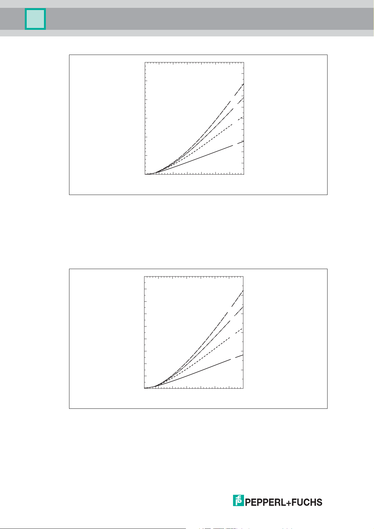
Figure 6.3 Silica sand in silo with smooth metallic walls; tensile load as a function of level L for
rope diameters 6mm (0.24in) and 4mm (0.16in)
A Silo diameter 12 m (40 ft)
B Silo diameter 9 m (30 ft)
C Silo diameter 6 m (20 ft)
D Silo diameter 3 m (10 ft)
24
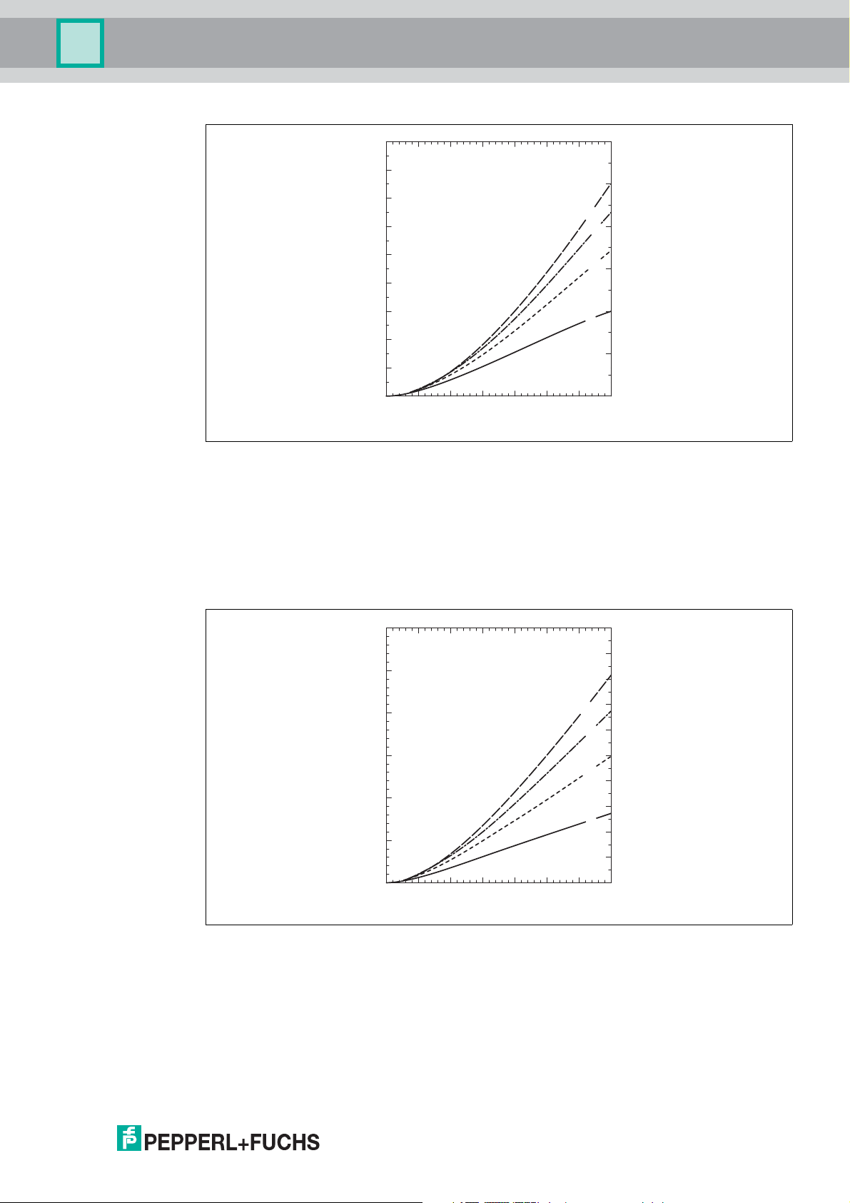
Figure 6.4 Polyethylene pellets in silo with smooth metallic walls; tensile load as a function of
A Silo diameter 12 m (40 ft)
B Silo diameter 9 m (30 ft)
C Silo diameter 6 m (20 ft)
D Silo diameter 3 m (10 ft)
level L for rope diameters 6 mm (0.24 in) and 4 mm (0.16 in)
2015-03
Page 25
Pulscon LTC57 PROFIBUS PA
F
[kN]
6mm
L[m]
F[kN]
4mm
A
B
C
D
0 5 10 15 20 25 30 35
0
4
8
12
16
20
24
28
32
36
0
4
8
12
16
20
24
F
[kN]
6mm
L[m]
F [kN]
4mm
A
B
C
D
0 5 10 15 20 25 30 35
0
10
20
30
40
50
60
0
4
8
12
16
20
24
28
32
36
40
Mounting
Figure 6.5 Wheat in silo with smooth metallic walls; tensile load as a function of level L for rope
diameters 6mm (0.24in) and 4mm (0.16in)
A Silo diameter 12 m (40 ft)
B Silo diameter 9 m (30 ft)
C Silo diameter 6 m (20 ft)
D Silo diameter 3 m (10 ft)
2015-03
Figure 6.6 Cement in silo with smooth metallic walls; tensile load as a function of level L for rope
A Tank diameter 12 m (40 ft)
B Tank diameter 9 m (30 ft)
C Tank diameter 6 m (20 ft)
D Tank diameter 3 m (10 ft)
diameters 6mm (0.24in) and 4mm (0.16in)
25
Page 26
Pulscon LTC57 PROFIBUS PA
Mounting
Bending strength of rod probes
Feature "Probe" Probe Bending strength [Nm]
Option L, P Rod 16 mm (0.63 in) 316L 30
Table 6.2
6.1.4 Notes on the process connection
Probes are mounted to the process connection with threaded connections or flanges. If during
this installation there is the danger that the probe end moves so much that it touches the tank
floor or cone at times, the probe must, if necessary, be shortened and fixed down.
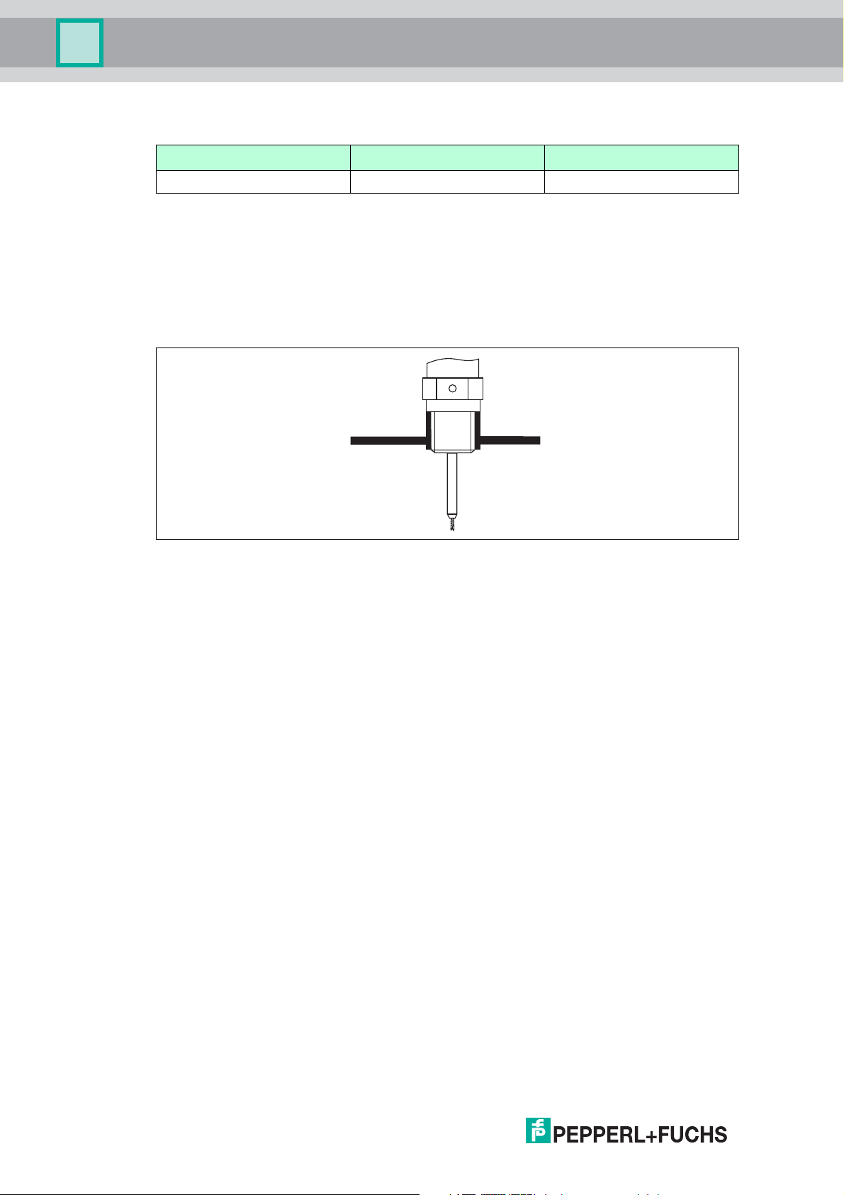
Threaded connection
Figure 6.7 Mounting with threaded connection; flush with the container ceiling
Seal
The thread as well as the type of seal comply to DIN 3852 part 1, screwed plug form A.
They can be sealed with the following types of sealing rings:
• Thread G3/4: according to DIN 7603 with the dimensions 27 x 32 mm
• Thread G1-1/2: According to DIN 7603 with the dimensions 48 x 55 mm
Please use a sealing ring according to this standard in the form A, C or D and of a material that
is resistant to the application.
26
2015-03
Page 27
Pulscon LTC57 PROFIBUS PA
≤150 (6)
H
mm (in)
ø ≤150 (6)
Mounting
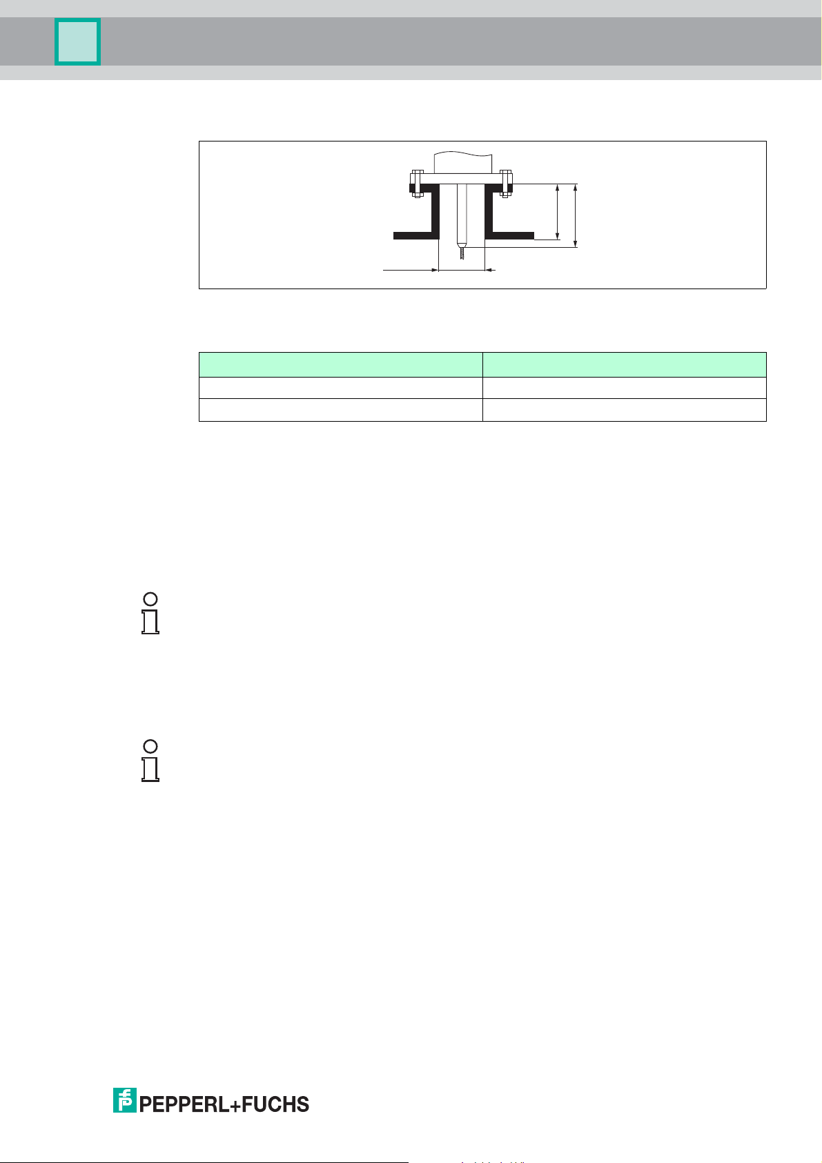
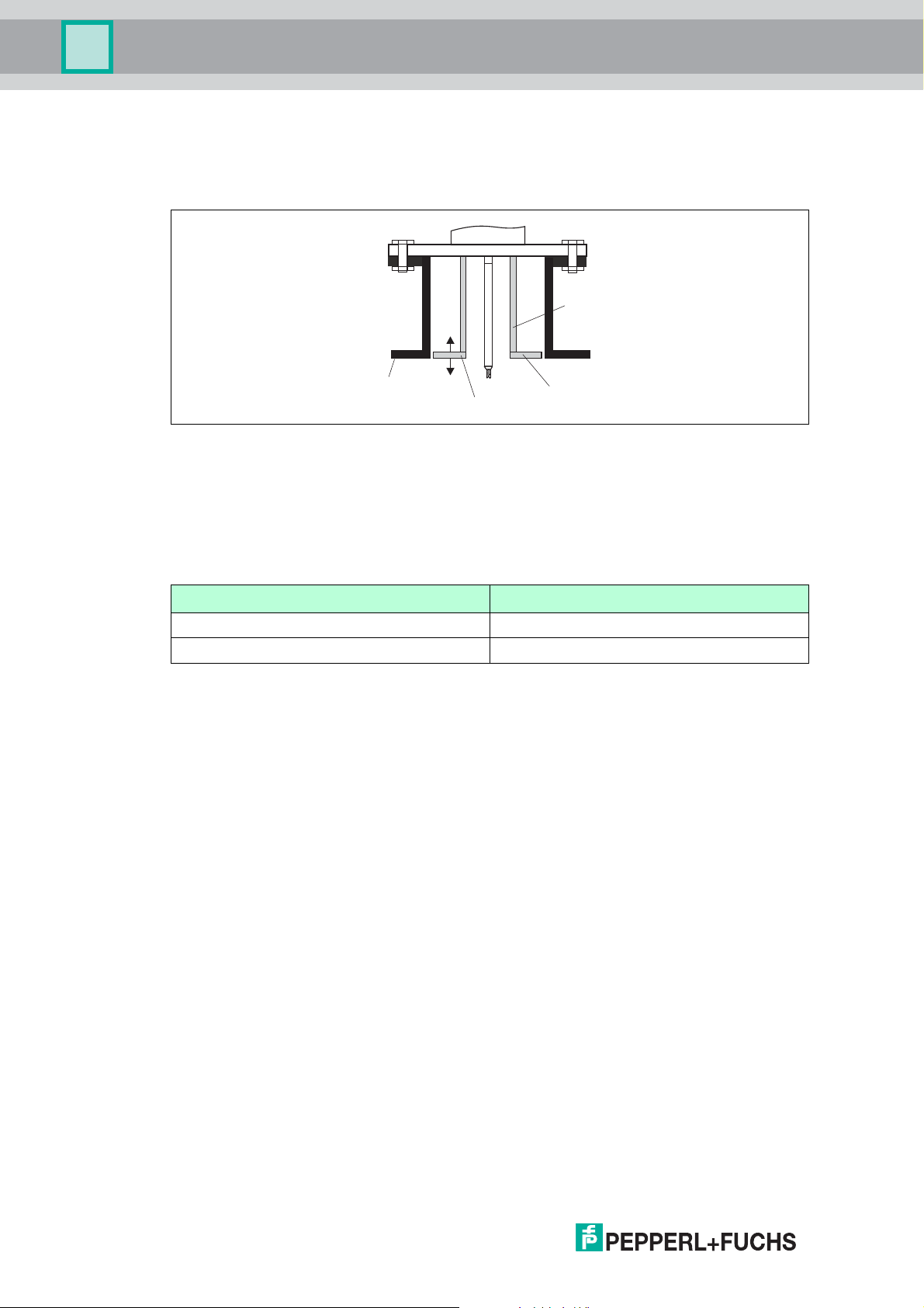
Nozzle mounting
Figure 6.8
Length H of the rigid part of the rope probe
Probe H
Rope Ø4 mm (0.16 in) 120mm(4.7in)
Rope Ø6 mm (0.24 in) 135mm(5.3in)
Table 6.3
• Permissible nozzle diameter: 150 mm (6 in).
For larger diameters the near range measuring capability may be reduced.
For nozzles DN300: see next section.
1
• Permissible nozzle height
: 150 mm (6 in).
For a larger height the near range measuring capability may be reduced.
Larger nozzle heights may be possible in special cases: see next section.
Note!
With thermally insulated vessels the nozzle should also be insulated in order to prevent
condensate formation.
Rod extension/centering
For devices with rope probes a rod extension/centering is available on request. It has to be
used if otherwise the probe rope comes into contact with the lower edge of the nozzle.
Note!
Centering disks with small diameters (DN40 and DN50) may only be used if there is no
significant build-up in the nozzle above the disk. The nozzle must not become clogged by the
product.
1
2015-03
Larger nozzle heights on request.
27
Page 28
Pulscon LTC57 PROFIBUS PA
1
2
3
4
Mounting
Installation in nozzles DN300
If installation in 300 mm/12 in nozzles is unavoidable, installation must be carried out in
accordance with the following sketch.
Figure 6.9
1 Lower edge of the nozzle
2 Approx. flush with the lower edge of the nozzle (±50 mm/2 in)
3 Plate
4 Pipe diameter 150 to 180 mm (6 to 7 in)
Nozzle diameter Plate diameter
300 mm (12 in) 280 mm (11 in)
400 mm (16 in) 350 mm (14 in)
Table 6.4
28
2015-03
Page 29
Pulscon LTC57 PROFIBUS PA
1
A
C
B
2
Mounting
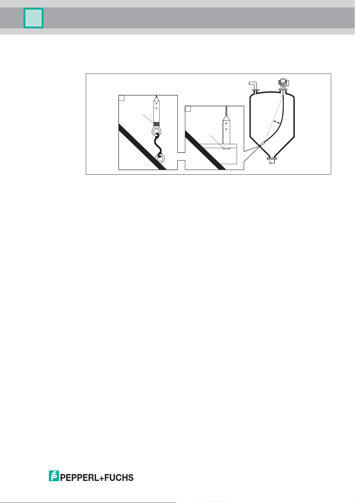
6.1.5 Securing the probe
Securing rope probes
Figure 6.10
A Sag of the rope: 1 cm per 1 m of the probe length (0.12 in per 1 ft of the probe length)
B Reliably grounded end of probe
C Reliably isolated end of probe
1 Mounting and contact with a bolt
2 Mounting kit isolated
• The end of the probe needs to be secured under the following conditions:
• if otherwise the probe sporadically comes into contact with the wall of the vessel, the
outlet cone, internal fittings or other parts of the installation.
• if otherwise the probe sporadically gets close to a concrete wall (minimum distance
0.5 m/20 in).
• The end of probe can be secured at its internal thread
• rope 4 mm (1/6 in), 316: M14
• rope 6 mm (1/4 in), 316: M20
• rope 6 mm (1/4 in), PA > steel: M14
• rope 8 mm (1/3 in), PA > steel: M20
• Preferably use the 6 mm (1/4 in) rope probe due to the higher tensile strength when fixing a
rope probe.
• The fixing must be either reliably grounded or reliably insulated. If it is not possible to
mount the probe weight with a reliably insulated connection, it can be secured using an
isolated eyelet, which is available as an accessory.
• In the case of a grounded fixing the search for a positive end-of-probe signal must be
activated. Otherwise an automatic probe length correction is impossible.
Navigation: Expert Sensor EOP evaluation EOP search mode
Setting: Positive EOP option
• In order to prevent an extremely high tensile load (e. g. due to thermal expansion) and the
risk of rope crack, the rope has to be slack. Make the rope longer than the required
measuring range such that there is a sag in the middle of the rope that is 1 cm/(1 m rope
length) [0.12 in/(1 ft rope length)].
2015-03
29
Page 30
Pulscon LTC57 PROFIBUS PA
1
2
3
4
5
6
∅ a
∅ b
≈50 (1.97)
∅ < 25 (1.0)
≈3 (0.12)
≈50 (1.97)
mm (in)
Mounting
Securing rod probes
• For Ex-approvals: For probe lengths 3 m (10 ft) a support is required.
• In general, rod probes must be supported if there is a horizontal flow (e. g. from an agitator)
or in the case of strong vibrations.
• Rod probes may only be supported at the end of the probe.
30
Figure 6.11
1 Probe rod, uncoated
2 Sleeve bored tight to ensure electrical contact between the rod and sleeve!
3 Short metal pipe, e. g. welded in place
4 Probe rod, coated
5 Plastic sleeve, e. g. PTFE, PEEK or PPS
6 Short metal pipe, e. g. welded in place
Warning!
Poor grounding of the end of probe may cause measuring errors.
• Apply a narrow sleeve which has good electrical contact to the probe.
Warning!
Welding may damage the main electronics module.
• Before welding: Ground the probe and dismount electronics.
2015-03
Page 31

Pulscon LTC57 PROFIBUS PA
Mounting
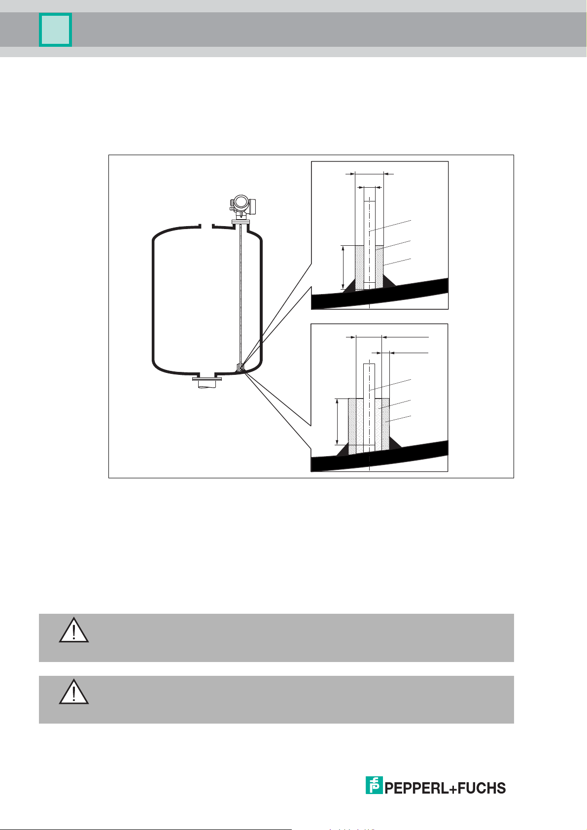
6.1.6 Special mounting conditions
Concrete silos
Installation, for example, into a thick concrete ceiling should be made flush with the lower
edge. Alternatively, the probe can also be installed into a pipe that must not protrude over the
lower edge of the silo ceiling. The pipe should be kept at a minimum length. Installation
suggestions see diagram.
Figure 6.12
1 Metal sheet
2 Metal tube
3 Extension rod/centering
≥≥100
4
1
2
≥≥100
4
ø80...150
3
(ø3.2...6)
mm (in)
Note for installations with rod extension/center washer (on request): Strong dust generation
can lead to build-up behind the center washer. This can cause an interference signal. For other
installation possibilities please contact Pepperl+Fuchs.
2015-03
31
Page 32

Pulscon LTC57 PROFIBUS PA
Ø1
6
(Ø 0.63)
Ø 16.5 (0.65)
Ø <26
(Ø <1.02)
mm (in)
1
2
Mounting
Installation from the side
Figure 6.13
• If installation from above is not possible, the device can also be mounted from the side.
• In this case, always fix the rope probe.
• Support rod probe if the lateral load bearing capacity is exceeded. Only fix rod probes at
the probe end.
Non-metallic vessels
Figure 6.14
1 Non-metallic vessel
2 Metal sheet or metal flange
32
To measure, device with a rod probe needs a metallic surface at the process connection.
Therefore:
• Select an instrument version with metal flange (minimum size DN50/2 in).
• Or: mount a metal sheet with a diameter of at least 200 mm (8 in) to the probe at the
process connection. Its orientation must be perpendicular to the probe.
2015-03
Page 33

Pulscon LTC57 PROFIBUS PA
MAX
1
3
MAX
2
Mounting
Vessels with heat insulation
Note!
If process temperatures are high, the device must be included in normal tank insulation to
prevent the electronics heating up as a result of heat radiation or convection. The insulation
may not exceed beyond the points labeled "MAX" in the drawings.
Figure 6.15 Process connection with thread
1 Tank insulation
2 Compact device
3 Sensor remote (feature "Probe design")
2
MAX MAX
mm (in)
Figure 6.16 Process connection with flange
3
1
1 Tank insulation
2 Compact device
3 Sensor remote (feature "Probe design")
2015-03
33
Page 34

Pulscon LTC57 PROFIBUS PA
Mounting
6.2 Mounting the device
6.2.1 Required mounting tools
• For mounting thread 3/4 in: Hexagonal wrench 36 mm
• For mounting thread 1-1/2 in: Hexagonal wrench 55 mm
• To shorten rod probes: Saw
• To shorten rope probes:
• Allen key AF3 mm (for 4 mm ropes) or AF4 mm (for 6 mm ropes)
• Saw or bolt cutter
• For flanges and other process connections: appropriate mounting tools
• To turn the housing: Hexagonal wrench 8 mm
6.2.2 Shortening the probe
Note!
When shortening the probe: Enter the new length of probe into the Quick Start Guide which
can be found in the electronics housing behind the display module.
Figure 6.17
Shortening rod probes
Rod probes must be shortened if the distance to the container floor or outlet cone is less than
10 mm (0.4 in). The rods of a rod probe are shortened by sawing at the bottom end.
34
2015-03
Page 35

Pulscon LTC57 PROFIBUS PA
B
A
C
Mounting
Shortening rope probes
Rope probes must be shortened if the distance to the container floor or outlet cone is less than
150 mm (6 in).
Figure 6.18
Rope material A B C Torque for set screws
316 4 mm (0.16 in) 40 mm (1.6 in) 3 mm 5 Nm (3.69 lbf ft)
316 6 mm (0.24 in) 55 mm (2.2 in) 4 mm 15 Nm (11.06 lbf ft)
PA > steel 6 mm (0.24 in) 40 mm (1.6 in) 3 mm 5 Nm (3.69 lbf ft)
PA > steel 8 mm (0.31 in) 55 mm (2.2 in) 4 mm 15 Nm (11.06 lbf ft)
Table 6.5
Shortening rope probes
1. Using an Allen key, loosen the set screws at the end-of-probe weight.
Note: The set screws have got a clamping coating in order to prevent accidental loosening.
Thus an increased torque might be necessary to loosen them.
2. Remove released rope from the weight.
3. Measure off new rope length.
4. Wrap adhesive tape around the rope at the point to be shortened to prevent it from fanning
out.
5. Saw off the rope at a right angle or cut it off with a bolt cutter.
6. Insert the rope completely into the weight.
7. Screw the set screws into place. Due to the clamping coating of the setscrews application
of a screw locking fluid is not necessary.
2015-03
35
Page 36

Pulscon LTC57 PROFIBUS PA
Mounting
6.2.3 Mounting the device
Mounting devices with thread
Figure 6.19
Devices with mounting thread are screwed into a welding boss or a flange and are usually also
secured with these.
Note!
• Tighten with the hexagonal nut only:
• Thread 3/4 in: Hexagonal wrench 36 mm
• Thread 1-1/2 in: Hexagonal wrench 55 mm
• Maximum permissible torque:
• Thread 3/4 in: 45 Nm
• Thread 1-1/2 in: 450 Nm
• Recommended torque when using the supplied aramid fibre seal and a process pressure
of 40 bar (580 psi):
• Thread 3/4 in: 25 Nm
• Thread 1-1/2 in: 140 Nm
• When installing in metal containers, take care to ensure good metallic contact between the
process connection and container.
Flange mounting
If a seal is used, be sure to use unpainted metal bolts to ensure good electrical contact
between probe flange and process flange.
36
2015-03
Page 37

Pulscon LTC57 PROFIBUS PA
Mounting
Mounting rope probes
Warning!
Electrostatic discharges may damage the electronics.
• Earth the housing before lowering the rope into the vessel.
Figure 6.20
When lowering the rope probe into the vessel, observe the following:
• Uncoil rope and lower it slowly and carefully into the vessel.
• Do not kink the rope.
• Avoid any backlash, since this might damage the probe or the vessel fittings.
Note!
Mounting rope probes in a partially full silo
It is not always possible to empty a silo which is already in operation. If a minimum of 2/3 of the
silo is empty, it is possible to install the probe into the partially filled silo. If possible, make a
visual check after the installation to see that the rope has not tangled or is lying such that it can
knot when the level falls. Before full accuracy is obtained the probe rope must hang fully
extended.
2015-03
37
Page 38

Pulscon LTC57 PROFIBUS PA
Mounting
6.2.4 Mounting the "Sensor remote" version
Note!
This section is only valid for devices of the version "Probe design" = "Sensor remote" (feature
"Probe design", option B).
For the version "Probe design = Sensor remote" the following is supplied:
• The probe with the process connection
• The electronics housing
• The mounting bracket for wall or pipe mounting of the electronics housing
• The connection cable (length as ordered). The cable has got one straight and one angled
plug (90°). Depending on the local conditions the angled plug can be connected at the
probe or at the electronics housing.
Warning!
The plugs of the connection cable may be damaged by mechanical stress.
• Mount the probe and the electronics housing tightly before connecting the cable.
• Lay the cable such that it is not exposed to mechanical stress. Minimum bending radius:
100 mm (4 in).
• When connecting the cable: Connect the straight plug before the angled one. Torque for
both coupling nuts: 6 Nm.
Note!
If the measuring point is exposed to strong vibrations, an additional locking compound (e. g.
Loctite 243) can be applied at the plug connectors.
Mounting the electronics housing
AB
52
(2)
70
(2.8)
122 (4.8)
158 (6.2)
86
(3.4)
50
140 (5.5)
175 (6.9)
(2)
mm (in)
38
Figure 6.21
A Wall mounting
B Pipe mounting
2015-03
Page 39

Pulscon LTC57 PROFIBUS PA
A
B
6 Nm
(4.42 lbf ft)
6 Nm
(4.42 lbf ft)
6 Nm
(4.42 lbf ft)
C
C
6 Nm
(4.42 lbf ft)
r = 100 (4)
min
r = 100 (4)
min
Mounting
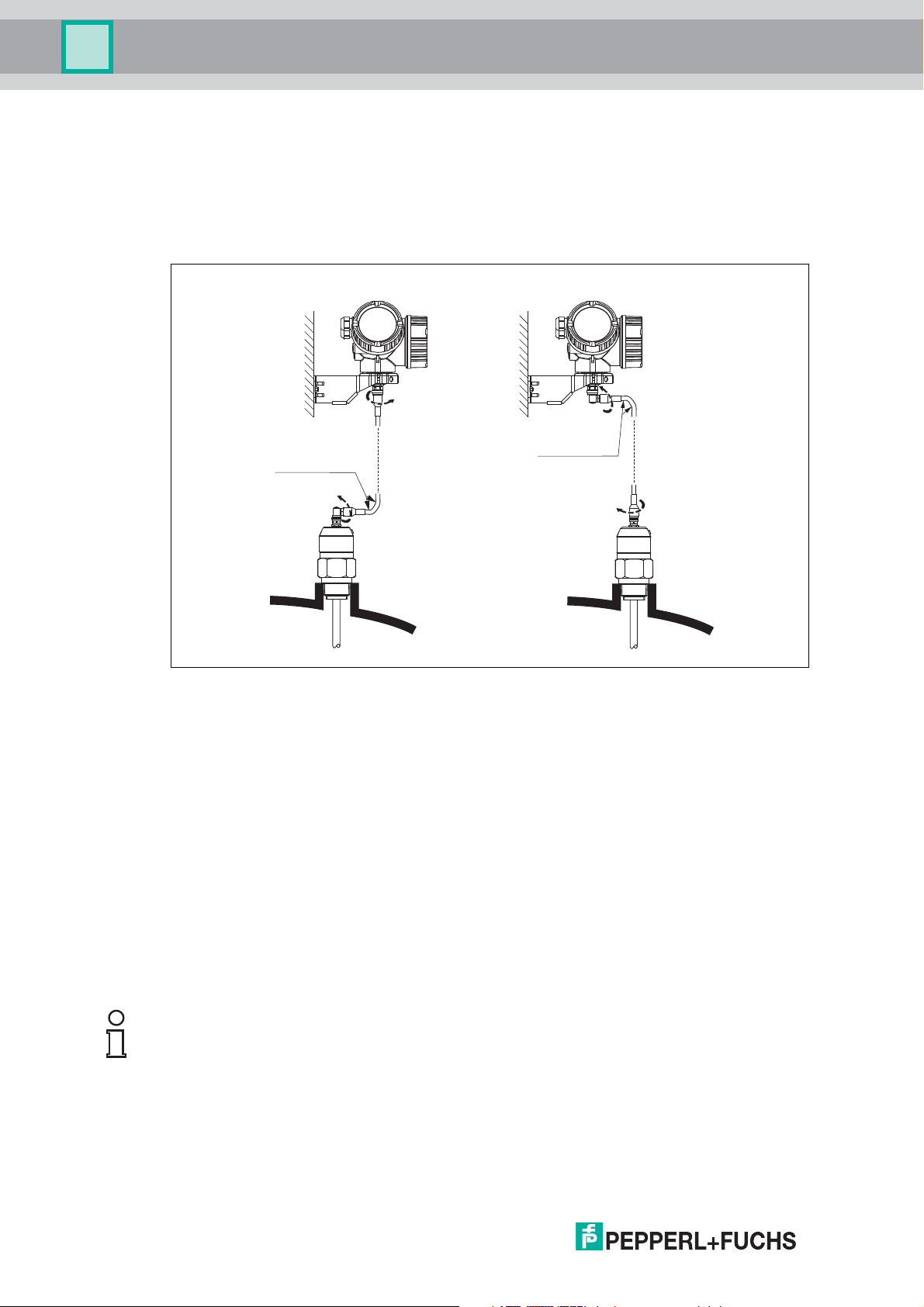
Connecting the cable
Required tools: open-end wrench AF18
Figure 6.22
A Angled plug at the probe
B Angled plug at the electronics housing
C Length of the remote cable as ordered
2015-03
39
Page 40

Pulscon LTC57 PROFIBUS PA
max.350°
8 mm
8 mm
1.
2.
3.
+
E
–
1
3 mm
1.
4.
3.2.
Mounting
6.2.5 Turning the transmitter housing
To provide easier access to the connection compartment or display module, the transmitter
housing can be turned:
Figure 6.23
Turning the transmitter housing
1. Unscrew the securing screw using an open-ended wrench.
2. Rotate the housing in the desired direction.
3. Tighten the securing screw (1.5 Nm for plastics housing; 2.5 Nm for aluminium or stainless
steel housing).
6.2.6 Turning the display module
Figure 6.24
Turning the display module
1. If present: Loosen the screw of the securing clamp of the electronics compartment cover
using an Allen key and turn the clamp 90° counterclockwise.
2. Unscrew cover of the electronics compartment from the transmitter housing.
3. Pull out the display module with a gentle rotation movement.
4. Rotate the display module into the desired position: Max. 8 x 45° in each direction.
5. Feed the spiral cable into the gap between the housing and main electronics module and
plug the display module into the electronics compartment until it engages.
6. Screw the cover of the electronics compartment firmly back onto the transmitter housing.
7. Tighten the securing clamp again using the Allen key (torque: 2.5 Nm).
2015-03
40
Page 41

Pulscon LTC57 PROFIBUS PA
Mounting
6.3 Post-installation check
• Is the device undamaged (visual inspection)?
• Does the device conform to the measuring point specifications?
For example:
– Process temperature
– Process pressure
– Ambient temperature range
– Measuring range
• Are the measuring point identification and labeling correct (visual inspection)?
• Is the device adequately protected from precipitation and direct sunlight?
• Are the securing screw and securing clamp tightened securely?
2015-03
41
Page 42

Pulscon LTC57 PROFIBUS PA
1
1
+
+
2
2
PA
[06/07]
-
-
1
3
+
+
2
4
PA
10 mm
2- wire
level
4-20 mA PFS
[26/27]
open
-
-
4
1
2
3
5
3+
4-
Electrical connection
7 Electrical connection
7.1 Connection conditions
7.1.1 Terminal assignment
PROFIBUS PA
Figure 7.1 Terminal assignment PROFIBUS PA
1 Cable screen: observe cable specifications
2 Switch output (open collector): terminals 3 and 4
3 Connection PROFIBUS PA: terminals 1 and 2
4 Terminal for potential equalization line
5 Cable entries
42
2015-03
Page 43

Pulscon LTC57 PROFIBUS PA
Electrical connection
Connection examples for the switch output
3+
4-
+
1
+
-
3+
4-
2
Connection of a relay
Suitable relays (examples):
• Solid-state relay: Phoenix Contact OV24DC/480AC/5 with mounting rail
connector UMK-1 OM-R/AMS
• Electromechanical relay: Phoenix
Contact PLC-RSC-12DC/21
Table 7.1
Note!
For optimum interference immunity we recommend to connect an external resistor (internal
resistance of the relay or Pull-up resistor) of < 1000 .
7.1.2 Cable specification
• Minimum cross-section: See the terminal specification in the Technical Information for the
device.
• For ambient temperature T
PROFIBUS PA
• Use a twisted, screened two-wire cable, preferably cable type A.
Note!
For further information on the cable specifications, see PNO Guideline 2.092 "PROFIBUS PA
User and Installation Guideline" and IEC 61158-2 (MBP).
Connection of a digital input
1 Pull-up resistor
2 Digital input
60 °C(140°F): use cable for temperature T
amb
amb
+20K.
2015-03
43
Page 44

Pulscon LTC57 PROFIBUS PA
21
3
4
2
1
4
3
Electrical connection
7.1.3 Device plug connectors
Note!
For the versions with fieldbus plug connector (M12 or 7/8 in), the signal line can be connected
without opening the housing.
Pin assignment of the M12 plug connector
Pin Meaning
1 Signal +
2 not connected
3 Signal -
4 Ground
Table 7.2
Pin assignment of the 7/8 in plug connector
Pin Meaning
1 Signal -
2 Signal +
3 not connected
4 Screen
Table 7.3
7.1.4 Power supply
PROFIBUS PA
Electrical Output
PA: 2-wire; PROFIBUS PA,
switch output
Table 7.4
a
Feature "Electrical Output" the product structure
b
Feature "Approval" of the product structure
c
Input voltages up to 35 V will not spoil the device.
d
Input voltages up to 35 V will not spoil the device.
a
Approval
•Non-Ex
b
Terminal voltage
9 ... 32 V
c
•ExnA
•ExnA(ia)
•Exic
•Exic(ia)
•Exd(ia)/XP
•Exta/DIP
•CSAGP
•Exia/IS
9 ... 30 V
d
• Ex ia + Ex d(ia)/IS + XP
Polarity sensitive no
FISCO/FNICO compliant according to
yes
IEC 60079-27
Table 7.5
44
2015-03
Page 45

Pulscon LTC57 PROFIBUS PA
Electrical connection
7.1.5 Overvoltage protection
If the measuring device is used for level measurement in flammable liquids which requires the
use of overvoltage protection according to DIN EN 60079-14, standard for test procedures
60060-1 (10 kA, pulse 8/20 s), overvoltage protection has to be ensured by an external
overvoltage protection module.
External overvoltage protection
For detailed information please refer to www.pepperl-fuchs.com
2015-03
45
Page 46

Pulscon LTC57 PROFIBUS PA
1.
2.
3.
10
(0.4)
10 (0.4
)
mm (in)
4.
5.
5.
Electrical connection
7.2 Connecting the device
Warning!
Explosion hazard!
• Comply with the relevant national standards.
• Observe the specifications in the Safety Instructions (SI).
• Only use the specified cable glands.
• Check whether the supply voltage matches the specifications on the nameplate.
• Before connecting the device: Switch the supply voltage off.
• Before switching on the supply voltage: Connect the potential bonding line to the exterior
ground terminal.
Required tools and accessories:
• For instruments with safety pin for the lid: AF3 Allen key
• Wire stripping pliers
• When using stranded wires: wire end sleeves.
Figure 7.2
Connecting the device
1. Loosen the screw of the securing clamp of the connection compartment cover and turn the
clamp 90° counterclockwise.
2. Unscrew the connection compartment cover.
3. Push the cable through the cable entry. To ensure tight sealing, do not remove the sealing
ring from the cable entry.
4. Strip the cable.
5. Strip the cable ends 10 mm (0.4 in). For stranded cables, also attach wire end ferrules.
6. Firmly tighten the cable glands.
2015-03
46
Page 47

Pulscon LTC57 PROFIBUS PA
mm (in)
≤ 3 (0.12)
Electrical connection
7. Connect the cable in accordance with the terminal assignment. See chapter 7.1.1.
Figure 7.3
8. When using screened cable: Connect the cable screen to the ground terminal.
9. Screw the cover onto the connection compartment.
10. For instruments with safety pin for the lid: Adjust the safety pin so that its edge is over the
edge of the display lid. Tighten the safety pin.
3
4
1
2
Pluggable spring-force terminals
Instruments have pluggable spring-force terminals. Rigid conductors or flexible conductors
with cable sleeve can directly be inserted and are contacted automatically.
To remove cables from the terminal: Press on the groove between the terminals using a flat-tip
screwdriver 3 mm (0.12 in) while pulling the cables out of the terminals.
Figure 7.4
2015-03
47
Page 48

Pulscon LTC57 PROFIBUS PA
Electrical connection
7.3 Post-connection check
• Are cables or the device undamaged (visual inspection)?
• Do the cables comply with the requirements?
• Do the cables have adequate strain relief?
• Are all cable glands installed, firmly tightened and correctly sealed?
• Does the supply voltage match the specifications on the transmitter nameplate?
• Is the terminal assignment correct? See chapter 7.1.1.
• If required: Is the protective earth connected correctly? See chapter 7.1.1.
• If supply voltage is present: Is the device ready for operation and do values appear on the
display module?
• Are all housing covers installed and firmly tightened?
• Is the securing clamp tightened correctly?
48
2015-03
Page 49

Pulscon LTC57 PROFIBUS PA
+
E
–
1
1
+
E
–
T
PROFIBUS DP
PROFIBUS PA
1
2
3
5
444
Operating options
8 Operating options
8.1 Overview
8.1.1 Local operation
Order code for "Display, operation", option D
"SD02"
1 Operation with push buttons 1 Operation with touch control
Table 8.1
8.1.2 Remote operation
Via PROFIBUS PA protocol
Order code for "Display, operation", option E
"SD03"
Figure 8.1
1 Segment coupler
2 Computer with Profiboard/Proficard and operating tool (e. g. PACTware)
3 PLC (Programmable Logic Controller)
4 Transmitter
5 Additional functions (valves etc.)
2015-03
49
Page 50

Pulscon LTC57 PROFIBUS PA
+
E
–
12
3
Operating options
Via service interface (CDI)
Figure 8.2
1 Service interface (CDI) of the measuring device (Common Data Interface)
2 Modem
3 Computer with PACTware operating tool
2015-03
50
Page 51

Pulscon LTC57 PROFIBUS PA
Operating options
8.2 Structure and function of the operating menu
8.2.1 Structure of the operating menu
Menu Parameter/submenu Meaning
Language parameter
Setup Parameter 1 ... Parameter N When all these parameters have been
Advanced setup Contains further submenus and parameters:
Diagnostics Diagnostic list Contains up to 5 currently active error
Event logbook
Device information Contains information needed to identify the
Measured values Contains all current measured values.
Data logging Contains the history of the individual
Simulation Used to simulate measured values or output
Device check Contains all parameters needed to check the
Expert.
c
System Contains all general device parameters
Contains all parameters of the
device (including those which
are already contained in one
of the above submenus). This
Sensor Contains all parameters needed to configure
menu is organized according
to the function blocks of the
Output • Contains all parameters needed to
device.
Communication Contains all parameters needed to configure
Diagnostics Contains all parameters needed to detect
Table 8.2
a
Defines the operating language of the on-site
display.
assigned appropriate values, the measured
should be completely configured in a
standard application.
• to adapt the device to special measuring
conditions.
• to process the measured value (scaling,
linearization).
• to configure the signal output.
messages.
b
Contains the last 20 messages (which are no
longer active).
device.
measuring values.
values.
measurement capability of the device.
which do not affect the measurement or the
communication interface.
the measurement.
configure the current output.
• Contains all parameters needed to
configure the switch output (PFS).
the digital communication interface.
and analyze operational errors.
a
In case of operation via operating tools (e. g. PACTware), the Language parameter is located at Setup Advanced setup
Display.
b
Only available for operation via on-site display.
c
On entering the Expert menu, an access code is always requested. If a customer specific access code has not been defined, 0000
has to be entered.
2015-03
51
Page 52

Pulscon LTC57 PROFIBUS PA
Operating options
8.2.2 User roles and related access authorization
The two user roles Operator and Maintenance have different write access to the parameters
if a device-specific access code has been defined. This protects the device configuration via
the local display from unauthorized access.
Access authorization to parameters
User role Read access Write access
Without access
code
(from the
factory)
Operator x x x –
Maintenance x x x x
Table 8.3
If an incorrect access code is entered, the user obtains the access rights of the Operator role.
Note!
The user role with which the user is currently logged on is indicated by the Access status
display (for display operation) or Access status tooling (for tool operation).
With access
code
Without access
code
(from the
factory)
With access
code
52
2015-03
Page 53

Pulscon LTC57 PROFIBUS PA
E
Operating options
8.2.3 Write protection via access code
Using the device-specific access code, the parameters for the measuring device configuration
are write-protected and their values can no longer be changed via local operation.
Define access code via local display
1. Navigate to: Setup Advanced setup Administration Define access code Define
access code
2. Define a max. 4-digit numeric code as an access code.
3. Repeat the same code in Confirm access code parameters.
The symbol appears in front of all write-protected parameters.
Define access code via operating tool (e. g. PACTware)
1. Navigate to: Setup Advanced setup Administration Define access code
2. Define a max. 4-digit numeric code as an access code.
Write protection is active.
Parameters that can always be changed
The write protection does not include certain parameters that do not affect the measurement.
Despite the defined access code, they can always be modified, even if the other parameters
are locked.
If no key is pressed for 10 minutes in the navigation and editing mode, the device automatically
locks the write-protected parameters. If the user goes from the navigation and editing mode
back to the measured value display mode, the device automatically locks the write-protected
parameters after 60 s.
Note!
• If write access is activated via access code, it can be also be deactivated only via the
access code.
• In the "Description of Device Parameters" documents, each write-protected parameter is
identified with the symbol.
8.2.4 Disabling write protection via access code
If the symbol appears on the local display in front of a parameter, the parameter is writeprotected by a device-specific access code and its value cannot be changed at the moment
using the local display.
Disabling write protection
The locking of the write access via local operation can be disabled by entering the devicespecific access code.
1. After you press , the input prompt for the access code appears.
2. Enter the access code.
The symbol in front of the parameters disappears; all previously write-protected
parameters are now re-enabled.
2015-03
53
Page 54

Pulscon LTC57 PROFIBUS PA
2.5 Nm (1.84 lbf ft )
3 mm
XXXXXXXXXXXXX
WPCDI
OFF
WP
ON
Operating options
8.2.5 Deactivation of the write protection via access code
Deactivating write protection via local display
1. Navigate to: Setup Advanced setup Administration Define access code Define
access code
2. Enter 0000.
3. Repeat 0000 in Confirm access code parameter.
The write protection is deactivated. Parameters can be changed without entering an
access code.
Deactivating write protection via operating tool (e. g. PACTware)
1. Navigate to: Setup Advanced setup Administration Define access code
2. Enter 0000.
The write protection is deactivated. Parameters can be changed without entering an
access code.
8.2.6 Write protection via lock switch
Unlike write protection via a user-specific access code, this allows write access to the entire
operating menu – other than the Contrast display parameter – to be locked.
The parameter values are now read only and cannot be edited any more (exception Contrast
display parameter) via:
•local display
• PROFIBUS PA protocol
3. 1.2.
–
+
E
4.
54
Figure 8.3
2015-03
Page 55

Pulscon LTC57 PROFIBUS PA
Operating options
Setting write protection via lock switch
1. Loosen the securing clamp.
2. Unscrew the electronics compartment cover.
3. Pull out the display module with a gentle rotation movement. To make it easier to access
the lock switch, attach the display module to the edge of the electronics compartment.
Display module is attached top the edge of the electronics compartment.
Figure 8.4
4. Set the lock switch (WP) on the main electronics module in the ON position enables the
hardware write protection. Set the lock switch (WP) on the main electronics module in the
OFF position (factory setting) disables the hardware write protection.
If the hardware write protection is enabled: The Hardware locked option is displayed
in the Locking status parameter. In addition to this, the symbol appears in the header of
the measured value display and in the navigation view in front of the parameters.
If the hardware write protection is disabled: No option is displayed in the Locking
status parameter. The symbol disappears in the header of the measured value display
and in the navigation view in front of the parameters
XXXX XXXXX
20.50
XXXX
Figure 8.5
5. Feed the spiral cable into the gap between the housing and main electronics module and
plug the display module into the electronics compartment in the desired direction until it
engages.
6. Screw the electronics compartment cover closed and tighten the securing clamp.
2015-03
55
Page 56

Pulscon LTC57 PROFIBUS PA
E
E
Operating options
8.2.7 Enabling and disabling the keypad lock
The keypad lock allows you disable access to the entire operating menu via local operation.
Thus navigating through the operating menu or modifying the values of individual parameters
is no longer possible. Only the measured values on the measured value display can be read
off.
The keylock is enabled and disabled via a context menu.
Enabling the keylock
Note!
SD03 display module only
The keylock is automatically enabled:
– after each restart of the device
– if the device is in the measured value display mode and has not been operated for at least
one minute.
Enabling the keylock manually
The device is in the measured value display mode.
1. Press the key for at least two seconds.
A context menu appears.
2. Select the Keylock on option from the context menu.
The keylock is enabled.
Note!
When attempting to access the operating menu while the keylock is enabled, the Keylock on
message appears.
Disabling the keylock
The keylock is enabled.
1. Press the key for at least two seconds.
A context menu appears.
2. Select the Keylock off option from the context menu.
The keylock is disabled.
2015-03
56
Page 57

Pulscon LTC57 PROFIBUS PA
3.1
3.2
2.1
2.2
2.4
2.5
1.1
1.2
1.3
1.4
2.3
2.6
1
2
3
45
ESCESC
OPENOPEN
OPENOPEN
E
ABC_
DEFG
User
HIJK
LMNO
PQRS
TUVW
XYZ
Aa1
3
4
0
12
9
5
687
20
Operating options
8.3 Display and operating module
8.3.1 Display appearance
Figure 8.6 Appearance of the display and operation module for on-site operation
1 Measured value display (1 value max. size)
1.1 Header containing tag and error symbol (if an error is active)
1.2 Measured value symbols
1.3 Measured value
1.4 Unit
2 Measured value display (1 bargraph and 1 value)
2.1 Bargraph for measured value 1
2.2 Measured value 1 (including unit)
2.3 Measured value symbols for measured value 1
2.4 Measured value 2
2.5 Unit for measured value 2
2.6 Measured value symbols for measured value 2
3 Representation of a parameter (here: a parameter with selection list)
3.1 Header containing parameter name and error symbol (if an error is active)
3.2
Selection list; marks the current parameter value.
4 Input matrix for numbers
5 Input matrix for alphanumeric and special characters
2015-03
57
Page 58

Pulscon LTC57 PROFIBUS PA
Operating options
Display symbols for the submenus
Symbol Meaning
Display/operation
Is displayed:
• in the main menu next to the selection Display/operation
• in the header, if you are in the Display/operation menu
Setup
Is displayed:
• in the main menu next to the selection Setup
• in the header, if you are in the Setup menu
Expert
Is displayed:
• in the main menu next to the selection Expert
• in the header, if you are in the Expert menu
Diagnostics
Is displayed:
• in the main menu next to the selection Diagnostics
• in the header, if you are in the Diagnostics menu
Table 8.4
Status signals
Failure (F)
A device error is present. The measured value is no longer valid.
Function check (C)
The device is in service mode (e. g. during a simulation).
Out of specification (S)
The device is operated:
• outside of its technical specifications (e. g. during startup or a cleaning)
• outside of the configuration carried out by the user (e. g. level outside
configured span)
Maintenance required (M)
Maintenance is required. The measured value is still valid.
Table 8.5
Display symbols for the locking state
Symbol Meaning
Display parameter
Marks display-only parameters which can not be edited.
58
Device locked
• In front of a parameter name: The device is locked via software and/or
hardware.
• In the header of the measured value screen: The device is locked via
hardware.
Table 8.6
2015-03
Page 59

Pulscon LTC57 PROFIBUS PA
Operating options
Measured value symbols
Symbol Meaning
Measured values
Level
Distance
Current output
Measured current
Terminal voltage
Temperature of the electronics or the sensor
Measuring channels
Measuring channel 1
Measuring channel 2
Status of the measured value
Status "Alarm"
The measurement is interrupted. The output assumes the defined alarm
value. A diagnostic message is generated.
Status "Warning"
The device continues measuring. A diagnostic message is generated.
Table 8.7
2015-03
59
Page 60

Pulscon LTC57 PROFIBUS PA
E
+
E
+
E
++
Operating options
8.3.2 Operating elements
Key Meaning
Minus key
For menu, submenu
Moves the selection bar upwards in a picklist.
For text and numeric editor
In the input mask, moves the selection bar to the left (backwards).
Plus key
For menu, submenu
Moves the selection bar downwards in a picklist.
For text and numeric editor
In the input mask, moves the selection bar to the right (forwards).
Enter key
For measured value display
• Pressing the key briefly opens the operating menu.
• Pressing the key for 2 s opens the context menu.
For menu, submenu
• Pressing the key briefly
Opens the selected menu, submenu or parameter.
• Pressing the key for 2 s for parameter
If present, opens the help text for the function of the parameter.
For text and numeric editor.
• Pressing the key briefly
– Opens the selected group.
– Carries out the selected action.
• Pressing the key for 2 s confirms the edited parameter value.
Escape key combination (press keys simultaneously)
For menu, submenu
• Pressing the key briefly
– Exits the current menu level and takes you to the next higher level.
– If help text is open, closes the help text of the parameter.
• Pressing the key for 2 s returns you to the measured value display ("home position").
For text and numeric editor
Closes the text or numeric editor without applying changes.
Minus/Enter key combination (press and hold down the keys simultaneously)
Reduces the contrast (brighter setting).
Plus/Enter key combination (press and hold down the keys simultaneously)
Increases the contrast (darker setting).
Minus/Plus/Enter key combination (press and hold down the keys
simultaneously)
For measured value display
Enables or disables the keypad lock.
Table 8.8
+
E
2015-03
60
Page 61

Pulscon LTC57 PROFIBUS PA
3
2
1
4
3
4
0
12
9
5
687
20
2
4
1
3
…
0
9
.
Operating options
8.3.3 Entering numbers and text
Numeric editor Tex t ed i t o r
1
Editing view
2
Display area of the entered values
3
Input mask
4
Operating elements
Table 8.9
Input mask
The following input symbols are available in the input mask of the numeric and text editor:
Numeric editor
Symbol Meaning
Selection of numbers from 0 to 9.
Inserts decimal separator at the input position.
Inserts minus sign at the input position.
–
Confirms selection.
Moves the input position one position to the left.
Exits the input without applying the changes.
Clears all entered characters.
Table 8.10
2015-03
61
Page 62

Pulscon LTC57 PROFIBUS PA
XYZ
ABC
_
…
Aa1
Operating options
Text editor
Symbol Meaning
Selection of letters from A to Z
Toggle
• between upper-case and lower-case letters
• for entering numbers
• for entering special characters
Confirms selection.
Switches to the selection of the correction tools.
Exits the input without applying the changes.
Clears all entered characters.
Table 8.11
Tex t co r re ct i on v ia
Symbol Meaning
Clears all entered characters.
Moves the input position one position to the right.
Moves the input position one position to the left.
Deletes one character immediately to the left of the input position.
Table 8.12
2015-03
62
Page 63

Pulscon LTC57 PROFIBUS PA
E
E
Operating options
8.3.4 Opening the context menu
Using the context menu, the user can call up the following menus quickly and directly from the
operational display:
•Setup
•Conf. backup disp.
•Simulation
Calling up and closing the context menu
The user is in the operational display.
1. Press for 2 s.
The context menu opens.
XXXXXXXXXX
Setup
Conf.backup disp
20.50
Simulation
kg/h
Figure 8.7
2. Press and simultaneously.
The context menu is closed and the operational display appears.
Calling up the menu via the context menu
1. Open the context menu.
2. Press to navigate to the desired menu.
3. Press to confirm the selection.
The selected menu opens.
2015-03
63
Page 64

Pulscon LTC57 PROFIBUS PA
E
+
(2s)
E
2x
E
+
-
+
+
-
+
E
+
-
+
Operating options
8.3.5 Envelope curve on the display and operating module
In order to assess the measuring signal, the envelope curve and – if a mapping has been
recorded – the mapping curve can be displayed:
64
Figure 8.8
2015-03
Page 65

Pulscon LTC57 PROFIBUS PA
2
98
3
4
56
7
8
1
DIP
ON
Integration into a PROFIBUS network
9 Integration into a PROFIBUS network
9.1 Overview of the device database files (GSD)
Manufacturer ID 93 (5D HEX)
Ident number 0E3B HEX
Profil version 3.02
GSD file Information and files under:
GSD file version
Table 9.1
9.2 Set device address
• www.pepperl-fuchs.com
• www.profibus.org
Figure 9.1 Address switches in terminal compartment
9.2.1 Hardware adressing
Setting hardware addressing
1. Set switch 8 to OFF.
2. Define the address with switches 1 to 7 according to the table below.
The address change becomes effective after 10 seconds. The device restarts
automatically.
Switch 1 2 3 4 5 6 7
Value in position ON 1 2 4 8 16 32 64
Value in position OFF 0 0 0 0 0 0 0
Table 9.2
Figure 9.2 Example of hardware addressing: switch 8 is in position OFF; switches 1 to 7 define
the address.
ON
98
1
3
2
2 + 8 = 10
4
56
7
DIP
8
2015-03
65
Page 66

Pulscon LTC57 PROFIBUS PA
Integration into a PROFIBUS network
9.2.2 Software addressing
Setting software addressing
1. Set switch 8 to ON.
2. The device restarts automatically. The address remains the same as before (factory
setting: 126).
3. Set the required address via the operating menu: Setup Device address
ON
98
1
3456
2
Figure 9.3 Example of software addressing; switch 8 is in position ON; the address is defined in
the operating menu (Menu Setup Device address)
7
DIP
8
66
2015-03
Page 67

Pulscon LTC57 PROFIBUS PA
Commissioning (via operating menu)
10 Commissioning (via operating menu)
10.1 Installation and function check
Make sure that all final checks have been completed before you start up your measuring point:
• Checklist "Post-installation check", see chapter chapter 6
• Checklist "Post-connection check", see chapter chapter 7.2
10.2 Setting the operating language
Factory setting: English or ordered local language
XXXX XXXXX
20.50
XXXX
Main menu
1.
2.
3.
4.
Language
Operation
Setup
Language
English
Deutsch
Español
Français
0104-1
English
0104-1
Language
English
Deutsch
Español
Français
Hauptmenü
Sprache
Betrieb
Setup
0104-1
0104-1
Deutsch
Figure 10.1 Using the example of the local display
2015-03
67
Page 68

Pulscon LTC57 PROFIBUS PA
F
L
D
E
100%
0%
LN
R
Commissioning (via operating menu)
10.3 Configuration of a level measurement
Figure 10.2 Parameters for level measurement with the guided radar
LN Probe length
D Distance
L Level
R Reference point of measurement
E Empty calibration (= zero)
F Full calibration (= span)
Note!
If for rope probes the DC value is less than 7, then measurement is not possible in the area of
the straining weight. In these cases, the maximum recommended value for the empty
calibration E is LN – 250 mm (LN – 10 in).
Configuring level measurement
1. Setup menu Device tag
Enter tag for measuring point.
2. Navigate to: Setup menu Device address
Enter the bus address of the device (only for software addressing).
3. Navigate to: Setup menu Distance unit.
Select distance unit.
4. Navigate to: Setup menu Bin type
Select bin type.
68
5. Navigate to: Setup menu Empty calibration
Enter the distance E between the reference point R and the minimum level (0 %).
6. Navigate to: Setup menu Full calibration.
Enter distance F between the minimum (0 %) and maximum (100 %) level.
7. Navigate to: Setup menu Level.
Displays the measured level L.
2015-03
Page 69

Pulscon LTC57 PROFIBUS PA
Commissioning (via operating menu)
8. Navigate to: Setup menu Distance.
Displays the distance D between the reference point R and the level L.
9. Navigate to: Setup menu Signal quality.
Displays the signal quality of the level echo.
10. For operation via local display:
Navigate to: Setup menu Mapping Mapping Confirm distance
Compare the displayed distance to the real distance in order to start the recording of the
mapping curve if required.
11. For operation via operating tool:
Navigate to: Setup menu Mapping Confirm distance
Compare the displayed distance to the real distance in order to start the recording of the
mapping curve if required.
10.4 Recording the reference curve
After the configuration of the measurement it is recommended to record the current envelope
curve as a reference curve. The reference curve can be used later on in the process for
diagnostic purposes. To record the reference curve use the Save reference curve parameter.
Navigation: Expert Diagnostics Envelope diagnostics Save reference curve
Meaning of the options
•No
No action
•Yes
The current envelope curve is saved as reference curve.
2015-03
69
Page 70

Pulscon LTC57 PROFIBUS PA
Commissioning (via operating menu)
10.5 Configuration of the on-site display
10.5.1 Factory settings of the on-site display for level measurements
Parameter Factory setting for devices
with 1 current output
Format display 1 value, max. size 1 value, max. size
Value 1 display Level linearized Level linearized
Value 2 display Distance Distance
Value 3 display Current output 1 Current output 1
Value 4 display None Current output 2
Table 10.1
10.5.2 Adjustment of the on-site display
The on-site display can be adjusted in the following menu:
Navigation: Setup Advanced setup Display
Factory setting for devices
with 2 current outputs
70
2015-03
Page 71

Pulscon LTC57 PROFIBUS PA
Commissioning (via operating menu)
10.6 Configuration management
After commissioning, you can save the current device configuration, copy it to another
measuring point or restore the previous device configuration. You can do so using the
Configuration management parameter and its options.
Navigation: Setup Advanced setup Configuration backup display Configuration
management
Meaning of the options
• Cancel
No action is executed and the user exits the parameter.
• Execute backup
A backup copy of the current device configuration in the HistoROM
is saved to the display module of the device. The backup copy comprises the transmitter
and sensor data of the device.
• Restore
The last backup copy of the device configuration is copied from the display module to the
HistoROM of the device. The backup copy comprises the transmitter and sensor data of
the device.
• Duplicate
The transmitter configuration is duplicated to another device using the transmitter display
module. The following parameters, which characterize the individual measuring point are
not included in the transmitted configuration: medium type
• Compare
The device configuration saved in the display module is compared to the current device
configuration of the HistoROM. The result of this comparison is displayed in the
Comparison result parameter.
• Clear backup data
The backup copy of the device configuration is deleted from the display module of the
device.
1
(built-in in the device)
Note!
While this action is in progress, the configuration cannot be edited via the local display and a
message on the processing status appears on the display.
Note!
If an existing backup is restored to a different device using the Restore option, it may occur
that some device functionalities are no longer available. In some cases even a device reset will
not restore the original status.
In order to transmit a configuration to a different device, the Duplicate option should always be
used.
10.7 Protection of the settings against unauthorized changes
There are two ways to protect the settings against unauthorized changes:
• Via parameter settings (software locking), see chapter 8
• Via locking switch (hardware locking), see chapter 8
1
2015-03
A HistoROM is a "non-volatile" device memory in the form of an EEPROM.
71
Page 72

Pulscon LTC57 PROFIBUS PA
E
E
Diagnostics and troubleshooting
11 Diagnostics and troubleshooting
11.1 General trouble shooting
11.1.1 General errors
Error Possible cause Remedial action
Device does not respond. Supply voltage does not match the
Values on the display invisible Contrast setting is too weak or too
"Communication error" is indicated
on the display when starting the
device or connecting the display
CDI communication does not
work.
Device measures incorrectly. Parametrization error Check parameterization and
Table 11.1
value indicated on the nameplate.
The cables do not contact the
terminals properly.
strong.
The plug of the display cable is not
connected correctly.
Display is defective. Replace display.
Electromagnetic interference Check grounding of the device.
Broken display cable or display
plug.
Wrong setting of the COM port on
the computer.
Connect the correct voltage.
Ensure electrical contact between
the cable and the terminal.
• Increase contrast by pressing
and simultaneously.
• Decrease contrast by pressing
and simultaneously.
Connect the plug correctly.
Exchange display.
Check the setting of the COM port
on the computer and change it if
necessary.
adjust it if necessary (see next
chapter).
2015-03
72
Page 73

Pulscon LTC57 PROFIBUS PA
Diagnostics and troubleshooting
11.1.2 Parametrization errors
Error Possible cause Remedial action
Measured value wrong If measured distance (Setup menu
No change of the measured value
when emptying/filling the tank
The Echo lost appears after
switching on the supply voltage.
Device displays a level when the
tank is empty.
Wrong slope of the level in the
entire measuring range
Table 11.2 Parametrization errors for level measurements
Distance) matches the real
distance:
Calibration error
If measured distance (Setup menu
Distance) does not match the
real distance:
An interference echo affects the
measurement.
An interference echo affects the
measurement.
Build-up at the probe. Clean the probe.
Error in the echo tracking Deactivate echo tracking: Expert
Noise level to high during
initialization phase.
Incorrect probe length • Carry out probe length
Wrong bin type selected. Set Bin type parameter correctly,
• Check and adjust the Empty
calibration parameter if
necessary, see page 102.
• Check and adjust the Full
calibration parameter if
necessary, see page 102.
• Check and adjust
Linearization submenu if
necessary, see page 116.
Perform mapping (Confirm
distance parameter), see
page 105.
Perform mapping (Confirm
distance parameter), see
page 105.
Sensor Echo tracking
Evaluation mode = History off).
Enter Empty calibration
parameter again, see page 102.
correction (Confirm probe
length parameter), see
page 130.
• Carry out mapping over entire
probe while the tank is empty
(Confirm distance
parameter), see page 105.
see 101.
2015-03
73
Page 74

Pulscon LTC57 PROFIBUS PA
1
4
3
XXXX XXXX X XXXX XXXXX
2
S
S
XX
20.50
5
X
i
S801
Menu
Supply voltage
Diagnostics and troubleshooting
11.2 Diagnostic information on local display
11.2.1 Diagnostic message
Faults detected by the self-monitoring system of the measuring device are displayed as a
diagnostic message in alternation with the measured value display.
Measured value display in alarm condition Diagnostic message
1
Status signal
2
Status symbol (symbol for event level)
3
Status symbol with diagnostics event
4
Event text
5
Operating elements
Table 11.3
Status signals
Table 11.4
Failure (F)
A device error is present. The measured value is no longer valid.
Function check (C)
The device is in service mode (e. g. during a simulation).
Out of specification (S)
The device is operated:
• outside of its technical specifications (e. g. during startup or a cleaning)
• outside of the configuration carried out by the user (e. g. level outside
configured span)
Maintenance required (M)
Maintenance is required. The measured value is still valid.
Status symbol (symbol for event level)
Alarm status
The measurement is interrupted. The signal outputs take on the defined
alarm condition. A diagnostic message is generated.
Warning status
The device continues to measure. A diagnostic message is generated.
Table 11.5
74
2015-03
Page 75

Pulscon LTC57 PROFIBUS PA
Diagnostics and troubleshooting
Diagnostics event and event text
The fault can be identified using the diagnostics event. The event text helps you by providing
information about the fault. In addition, the corresponding symbol is displayed before the
diagnostics event.
Status symbol Status signal Event number Event text
Table 11.6 Example
If two or more diagnostic messages are pending simultaneously, only the message with the
highest priority is shown. Additional pending diagnostic messages can be shown in
Diagnostic list submenu.
Diagnostics event
441 Curr.output 1
3-digit number
Note!
Past diagnostic messages that are no longer pending are shown as follows:
• On the local display: in Event logbook submenu
• In the software: via the Event List /HistoROM function.
Operating elements
Operating functions in menu, submenu
Plus key
Opens the message about the remedial measures.
E
Table 11.7
Enter key
Opens the operating menu.
2015-03
75
Page 76

Pulscon LTC57 PROFIBUS PA
XXXX XXXX X XXXX XXXXX
S
S
XX
20.50
X
i
S801
Menu
S
(ID:203)
S801 0d00h02m25s
1
2
4
6
3
5
Increase supply voltage
S801 Supply voltage
Diagnostic list
Diagnostics
1
Diagnostics
2
Diagnostics
3
Supply voltage
Supply voltage
1.
2.
3.
E
Diagnostics and troubleshooting
Remedial measures
Figure 11.1 Message for remedial measures
1 Diagnostic information
2 Short text
3 Service ID
4 Diagnostic behavior with diagnostic code
5 Operation time of occurrence
6 Remedial measures
Calling up remedial measures during a diagnostic message
The user is in the diagnostic message.
1. Press ( symbol).
Diagnostic list submenu opens.
2. Select the desired diagnostic event with or and press .
The message for the remedial measures for the selected diagnostic event opens.
3. Press and simultaneously.
The message for the remedial measures closes.
76
2015-03
Page 77

Pulscon LTC57 PROFIBUS PA
E
Diagnostics and troubleshooting
Calling up remedial measures in diagnostics menu
The user is in the Diagnostics menu at an entry for a diagnostics event, e. g. in Diagnostic
list submenu or in Previous diagnostics.
1. Press .
The message for the remedial measures for the selected diagnostic event opens.
2. Press and simultaneously.
The message for the remedial measures closes.
11.3 Diagnostic event in the operating tool
If a diagnostic event is present in the device, the status signal appears in the top left status in
the operating tool along with the corresponding symbol for event level in accordance with
NAMUR NE 107:
• Failure (F)
• Function check (C)
• Out of specification (S)
• Maintenance required (M)
Calling up remedial measures
1. Navigate to the Diagnostics menu.
In the Actual diagnostics parameter, the diagnostic event is shown with event text.
2. On the right in the display range, hover the cursor over the Actual diagnostics parameter.
A tool tip with remedial measures for the diagnostic event appears.
2015-03
77
Page 78

Pulscon LTC57 PROFIBUS PA
E
Diagnostics and troubleshooting
11.4 Diagnostic list
In the Diagnostic list submenu, up to 5 currently pending diagnostic messages can be
displayed. If more than 5 messages are pending, the messages with the highest priority are
shown on the display.
Navigation: Diagnostics Diagnostic list
Calling up and closing the remedial measures
1. Press .
The message for the remedial measures for the selected diagnostic event opens.
2. Press and simultaneously.
The message about the remedial measures closes.
11.5 List of diagnostic events
Diagnostic
number
Diagnostic of sensor
003 Broken probe detected
046 Build-up detected Clean sensor F Alarm
104 HF cable
105 HF cable
106 Sensor
Diagnostic of electronic
242 Software incompatible
252 Modules incompatible
261 Electronic modules
Short text Repairing action Status signal
(from the
factory)
1. Check map
2. Check sensor
1. Dry HF cable connection and
check sealing
2. Change HF cable
1. Tighten HF cable connection
2. Check sensor
3. Change HF cable
1. Check sensor
2. Check HF cable
3. Contact service
1. Check software
2. Flash or change main electronics
module
1. Check electronic modules
2. Change I/O or main electronic
module
1. Restart device
2. Check electronic modules
3. Change I/O module or main electronics
F Alarm
F Alarm
F Alarm
F Alarm
F Alarm
F Alarm
F Alarm
Diagnostic
behavior
(from the
factory)
2015-03
78
Page 79

Pulscon LTC57 PROFIBUS PA
Diagnostics and troubleshooting
Diagnostic
number
262 Module connection
270 Main electronic failure Change main electronic module F Alarm
271 Main electronic failure
272 Main electronic failure
273 Main electronic failure
275 I/O module failure Change I/O module F Alarm
276 I/O module failure
282 Data storage
283 Memory content
311 Electronic failure
311 Electronic failure Maintenance required!
Diagnostic of configuration
410 Data transfer
412 Download process Download active, please wait C Warning
435 Linearization Check linearization table F Alarm
437 Configuration
438 Dataset
482 Block in OOS Set block in AUTO mode F Alarm
484 Simulation failure mode Deactivate simulation C Alarm
485 Simulation measured
494 Switch output
Short text Repairing action Status signal
(from the
factory)
1. Check module connection
2. Change electronic modules
1. Restart device
2. Change main electronic module
1. Restart device
2. Contact service
1. Emergency operation via display
2. Change main electronics
1. Restart device
2. Change I/O module
1. Restart device
2. Contact service
1. Transfer data or reset device
2. Contact service
1. Transfer data or reset device
2. Contact service
1. Do not perform reset
2. Contact service
1. Check connection
2. Retry data transfer
1. Restart device
incompatible
2. Contact service
1. Check data set file
2. Check device configuration
3. Up- and download new configuration
Deactivate simulation C Warning
value
Deactivate simulation switch output C Warning
simulation
F Alarm
F Alarm
F Alarm
F Alarm
F Alarm
F Alarm
F Alarm
F Alarm
M Warning
F Alarm
F Alarm
M Warning
Diagnostic
behavior
(from the
factory)
2015-03
79
Page 80

Pulscon LTC57 PROFIBUS PA
Diagnostics and troubleshooting
Diagnostic
number
Short text Repairing action Status signal
(from the
factory)
Diagnostic
behavior
(from the
factory)
495 Diagnostics event
Deactivate simulation C Warning
simulation
497 Block output simulation Deactivate simulation C Warning
585 Simulation distance Deactivate simulation C Warning
Diagnostic of process
801 Energy too low Increase supply voltage S Warning
825 Operating temperature
1. Check ambient temperature
S Warning
2. Check process temperature
825 Operating temperature
1. Check ambient temperature
F Alarm
2. Check process temperature
921 Change of reference
1. Check reference configuration
S Warning
2. Check pressure
3. Check sensor
936 EMC interference Check installation on EMC F Alarm
941 Echo lost Check DC value F Alarm
942 In safety distance
1. Check level
S Alarm
2. Check safety distance
3. Reset self holding
943 In blocking distance Reduced accuracy
S Warning
Check level
944 Level range Reduced accuracy
S Warning
Level at process connection
950 Advanced diagnostic 1
Maintain your diagnostic event M Warning
to 2 occurred
Table 11.8
a
b
c
a
Diagnostic status is changeable.
b
Diagnostic status is changeable.
c
Diagnostic status is changeable.
80
2015-03
Page 81

Pulscon LTC57 PROFIBUS PA
E
Diagnostics and troubleshooting
11.6 Event logbook
11.6.1 Event history
A chronological overview of the event messages that have occurred is provided in the Event
list submenu
Navigation: Diagnostics Event logbook Event list
A maximum of 20 event messages can be displayed in chronological order. If the advanced
HistoROM function is enabled in the device (order option), up to 100 entries can be displayed.
The event history includes entries for:
• Diagnostic events
• Information events
In addition to the operation time of its occurrence, each event is also assigned a symbol that
indicates whether the event has occurred or is ended:
• Diagnostic event
• : Event has occurred
• : Event has ended
• Information event
• : Event has occurred
1
.
Calling up and closing the remedial measures
1. Press .
The message for the remedial measures for the selected diagnostic event opens.
2. Press and simultaneously.
The message about the remedial measures closes.
11.6.2 Filtering the event logbook
Using the Filter options parameter, you can define which category of event messages is
displayed in the Event list submenu.
Navigation: Diagnostics Event logbook Filter options
Filter categories
•All
• Failure (F)
• Function check (C)
• Out of specification (S)
• Maintenance required (M)
• Information
1
This submenu can only be accessed via the local display. When operating the device via Software, the event
2015-03
history can be displayed using Event List /HistoROM function.
81
Page 82

Pulscon LTC57 PROFIBUS PA
Diagnostics and troubleshooting
11.6.3 List of information events
Info number Info name
I1000 -------- Device OK
I1089 Power on
I1090 Configuration reset
I1091 Configuration changed
I1092 Trend data deleted
I1110 Write protection switch changed
I1137 Electronic changed
I1151 History reset
I1154 Reset terminal voltage min/max
I1155 Reset electronic temperature
I1156 Memory error trend
I1157 Memory error event list
I1185 Display backup done
I1186 Restore via display done
I1187 Settings downloaded with display
I1188 Display data cleared
I1189 Backup compared
I1256 Display: access status changed
I1264 Safety sequence aborted
I1335 Firmware changed
I1398 CDI: access status changed
I1512 Download started
I1513 Download finished
I1514 Upload started
I1515 Upload finished
Table 11.9
82
2015-03
Page 83

Pulscon LTC57 PROFIBUS PA
Diagnostics and troubleshooting
11.7 Firmware history
Date Software
version
07.2011 01.00.zz Original software BA01009O/98/EN/
11.2014 01.01.zz • Support of
Table 11.10
Modifications Operating
Instructions
10.10
BA01009O/98/EN/
SD03
• additional
languages
• HistoROM
functionality
enhanced
• Advanced
Diagnostic
function block
integrated
• Improvements
and bugfixes
14.14
Description of
Parameters
GP01001O/98/EN/
10.10
GP01001O/98/EN/
13.14
Technical
Information
TI01004O/98/EN/
13.11
TI01004O/98/EN/
17.14
2015-03
83
Page 84

Pulscon LTC57 PROFIBUS PA
Maintenance
12 Maintenance
The measuring device requires no special maintenance.
12.1 Exterior cleaning
When exterior-cleaning the device, always use cleaning agents that do not attack the surface
of the housing and the seals.
84
2015-03
Page 85

Pulscon LTC57 PROFIBUS PA
Repairs
13 Repairs
13.1 General information on repairs
13.1.1 Repair concept
The Pepperl+Fuchs repair concept assumes that the devices have a modular design and that
repairs can be done by the Pepperl+Fuchs service or specially trained customers.
Spare parts are contained in suitable kits. They contain the related replacement instructions.
For more information on service and spare parts, contact the Service Department at
Pepperl+Fuchs.
13.1.2 Repairs to Ex-approved devices
When carrying out repairs to Ex-approved devices, please note the following:
• Repairs to Ex-approved devices may only be carried out by trained personnel or by the
Pepperl+Fuchs Service.
• Comply with the prevailing standards, national Ex-area regulations, safety instructions (SI)
and certificates.
• Only use original spare parts from Pepperl+Fuchs.
• When ordering a spare part, please note the device designation on the nameplate. Only
replace parts with identical parts.
• Carry out repairs according to the instructions. On completion of repairs, carry out the
specified routine test on the device.
• Only Pepperl+Fuchs Service may convert a certified device into a different certified variant.
• Document all repair work and conversions.
13.1.3 Replacement of an electronics module
If an electronics module has been replaced, it is not necessary to perform a new basic setup as
the calibration parameters are stored in the HistoROM which is located in the housing.
However, after exchanging the main electronics module it may be necessary to record a new
mapping (interference echo suppression).
13.1.4 Replacement of a device
After a complete device or electronic module has been replaced, the parameters can be
downloaded into the instrument again in one of the following ways:
• Via the display module
Condition: The configuration of the old device has been saved in the display module.
•Via PACTware
Condition: The configuration of the old device has been saved to the computer via
PACTware.
You can continue to measure without carrying out a new setup. Only a linearization and a tank
map (interference echo suppression) have to be recorded again.
2015-03
85
Page 86

Pulscon LTC57 PROFIBUS PA
Spare parts for:
Ser.-no.:
Cover (front)
Cover (right)
IO module
Display
Sensor
Pos. no.
1
2
3
4
5
6
Spare part Spare no./structure
Main electr.
Additional information: www.pepperl-fuchs.com
3
4
1
5
2
6
Repairs
13.2 Spare parts
• A few interchangeable measuring device components are identified by a spare part
nameplate. This contains information about the spare part.
• The connection compartment cover of the device contains a spare part nameplate that
includes the following information:
• A list of the most important spare parts for the measuring device, including their
ordering information.
• For additional information of spare parts, refer to www.pepperl-fuchs.com.
There, all spare parts for the measuring device are listed, including the order code, and
can be ordered. If available, the corresponding Installation Instructions can also be
downloaded there.
Figure 13.1 Example for spare part nameplate in connection compartment cover
Note!
Measuring device serial number:
• Is located on the device and spare part nameplate.
• Can be read out via the "Serial number" parameter in the "Device information" submenu.
13.3 Return
The measuring device must be returned if repairs or a factory calibration are required, or if the
wrong measuring device has been ordered or delivered. According to legal regulations,
Pepperl+Fuchs, as an ISO-certified company, is required to follow certain procedures when
handling returned products that are in contact with medium.
To ensure swift, safe and professional device returns, please read the return procedures and
conditions on the Pepperl+Fuchs website at (www.pepperl-fuchs.com).
13.4 Disposal
Observe the following notes during disposal:
• Observe valid federal/national regulations.
• Ensure proper separation and reuse of the device components.
2015-03
86
Page 87

Pulscon LTC57 PROFIBUS PA
222 (8.74)
mm (in)
Accessories
14 Accessories
14.1 Device-specific accessories
14.1.1 Weather protection cover
Accessory Description
Weather protection cover
Table 14.1
273.8(10.8)273.8(10.8)
164 (6.46)164 (6.46)
b
b
35°
35°
mm (in)mm (in)
298.5(11.8)298.5(11.8)
255.1(10)255.1(10)
55°
55°
a
a
155 (6.1)155 (6.1)
65°
65°
a 37.8 mm (1.49 in)
b 54 mm (2.13 in)
The weather protection cover can be ordered together with the device
(product structure, feature "Accessory enclosed", option B "Weather
protection cover").
Alternatively, it can be separately ordered as an accessory.
2015-03
87
Page 88

Pulscon LTC57 PROFIBUS PA
122 (4.8)
52
(2)
86
(3.4)
70
(2.8)
140 (5.5)
158 (6.2)
175 (6.9)
50
(2)
AB
mm (in)
Accessories
14.1.2 Mounting bracket for the electronics housing
Accessory Description
Mounting bracket for the
electronics housing
Table 14.2
A Wall mounting
B Pipe mounting
For the "Sensor remote" device version, the mounting bracket is part of
the delivery. If required, it can also be ordered as an accessory.
88
2015-03
Page 89

Pulscon LTC57 PROFIBUS PA
D
1
2
Accessories
14.1.3 Mounting kit, isolated
Accessory Description
Mounting kit, isolated
Table 14.3
1 Insulating sleeve
2 Eye-bolt
For reliably insulated fixing of the probe.
Maximum process temperature: 150 °C(300°F)
For rope probes 4 mm (1/6 in) or 6 mm (1/4 in) with PA > steel:
•Eye-bolt M8 DIN580
• Diameter D = 20 mm (0.8 in)
For rope probes 6 mm (1/4 in) or 8 mm (1/3 in) with PA > steel:
• Eye-bolt M10 DIN 580
• Diameter D = 25 mm (1 in)
Due to the risk of electrostatic charge, the insulating sleeve is not
suitable for use in hazardous areas. In these cases the fixing must be
reliably grounded.
The mounting kit can also be ordered directly with the device (see
product structure, feature "Accessory enclosed", option G "Mounting kit,
isolated, rope").
2015-03
89
Page 90

Pulscon LTC57 PROFIBUS PA
Accessories
14.2 Communication-specific accessories
Accessory Description
HART Loop Converter
KFD2-HLC-Ex1.D.**
Table 14.4
Accessory Description
WirelessHART-Adapter
WHA-ADP-F8B2-*-P*-*
Table 14.5
Note!
For details refer to data sheet on www.pepperl-fuchs.com.
Evaluates the dynamic HART variables and converts them to
analog current signals or limit values.
Connects field devices to a WirelessHART network. The
WirelessHART adapter can be mounted directly at a HART
device and is easily integrated into an existing HART
network. It ensures safe data transmission and can be
operated in parallel with other wireless networks.
14.3 Service-specific accessories
Accessory Description
PACTware PACTware is an operating software with graphical support
Table 14.6
(MS Windows) for intelligent transmitters with the
communication protocols HART and PROFIBUS PA.
Note!
For details refer to data sheet on www.pepperl-fuchs.com.
14.4 System components
Accessory Description
KFD2-STC-Ex1 Transmitter power supply with power supply for safe isolation
Table 14.7
Accessory Description
KFD2-STC-1 Transmitter power supply for 2-wire sensors or transmitters
Table 14.8
Note!
For details refer to data sheet on www.pepperl-fuchs.com.
of 4 ... 20 mA current circuits. Provides bi-directional
HART communication.
exclusively for non-Ex areas. Provides bi-directional HART
communication.
90
2015-03
Page 91

Pulscon LTC57 PROFIBUS PA
Operating menu
15 Operating menu
15.1 Overview of the operating menu (display module)
Language page 137
Setup page 101
Device tag page 101
Device address page 101
Distance unit page 101
Bin type page 101
Empty calibration page 102
Full calibration page 102
Level page 103
Distance page 103
Signal quality page 104
Mapping page 107
Confirm distance page 107
Mapping end point page 107
Record map page 107
Distance page 107
Analog inputs
Analog input 1 to 6 page 108
Channel page 108
PV filter time page 108
Fail safe type page 109
Fail safe value page 109
Advanced setup page 110
Locking status page 110
Access status display page 111
Enter access code page 111
Level page 112
Medium type page 112
Medium property page 112
Process property page 113
Advanced process conditions page 114
Level unit page 114
Blocking distance page 115
Level correction page 115
2015-03
91
Page 92

Pulscon LTC57 PROFIBUS PA
Operating menu
Linearization page 116
Safety settings page 125
Linearization type page 116
Unit after linearization page 118
Free text page 118
Maximum value page 119
Diameter page 119
Intermediate height page 120
Table mode page 121
Activate table page 123
Edit table page 124
Level page 124
Customer value page 124
Output echo lost page 125
Value echo lost page 125
Ramp at echo lost page 126
Blocking distance page 127
SIL/WHG confirmation page 128
Deactivate SIL/WHG page 128
Reset write protection page 128
Code incorrect page 128
Probe settings page 129
Probe grounded page 129
Probe length correction page 131
Confirm probe
length
Present probe
length
page 131
page 131
92
2015-03
Page 93

Pulscon LTC57 PROFIBUS PA
Operating menu
Switch output page 132
Display page 137
Switch output function page 132
Assign status page 133
Assign limit page 133
Assign diagnostic behavior page 133
Switch-on value page 134
Switch-on delay page 135
Switch-off value page 135
Switch-off delay page 136
Failure mode page 136
Switch status page 136
Invert output signal page 136
Language page 137
Format display page 138
Value 1 to 4 display page 139
Decimal places 1 to 4 page 139
Display interval page 140
Display damping page 140
Header page 140
Header text page 141
Separator page 141
Number format page 141
Decimal places menu page 141
Backlight page 142
Contrast display page 142
Configuration backup display page 143
Operating time page 143
Last backup page 143
Configuration management page 144
Comparison result page 145
Administration page 146
Device reset page 147
Define access code page 146
Define access
code
Confirm access
code
2015-03
page 148
page 148
93
Page 94

Pulscon LTC57 PROFIBUS PA
Operating menu
Diagnostics page 149
Actual diagnostics page 149
Previous diagnostics page 149
Operating time from restart page 150
Operating time page 150
Diagnostic list page 151
Diagnostics 1 to 5 page 151
Event logbook page 152
Filter options page 152
Event list page 152
Device information page 153
Device tag page 153
Serial number page 153
Firmware version page 153
Device name page 153
Order code page 153
Extended order code 1 to 3 page 154
Status PROFIBUS Master Config page 154
PROFIBUS ident number page 154
Measured values page 155
Distance page 155
Level linearized page 155
Terminal voltage 1 page 155
Switch status page 155
Analog inputs
Analog input 1 to 6 page 156
Channel page 156
Out value page 156
Out status page 157
Out status HEX page 157
Data logging page 158
Assign channel 1 to 4 page 158
Logging interval page 159
Clear logging data page 159
Display channel 1 to 4 page 160
94
2015-03
Page 95

Pulscon LTC57 PROFIBUS PA
Operating menu
Simulation page 161
Assign measurement variable page 161
Value process variable page 161
Switch output simulation page 161
Switch status page 162
Simulation device alarm page 162
Diagnostic event category page 162
Simulation diagnostic event page 163
Device check page 164
Start device check page 164
Result device check page 164
Last check time page 164
Level signal page 164
Launch signal page 165
2015-03
95
Page 96

Pulscon LTC57 PROFIBUS PA
Operating menu
15.2 Overview of the operating menu (operating tool)
Setup page 101
Device tag page 101
Device address page 101
Distance unit page 101
Bin type page 101
Empty calibration page 102
Full calibration page 102
Level page 103
Distance page 103
Signal quality page 104
Confirm distance page 107
Present mapping page 106
Mapping end point page 107
Record map page 107
Analog inputs
Analog input 1 to 6 page 108
Channel page 108
PV filter time page 108
Fail safe type page 109
Fail safe value page 109
Advanced setup page 110
Locking status page 110
Access status tooling page 110
Enter access code page 111
Level page 112
Medium type page 112
Medium property page 112
Process property page 113
Advanced process conditions page 114
Level unit page 114
Blocking distance page 115
Level correction page 115
96
2015-03
Page 97

Pulscon LTC57 PROFIBUS PA
Operating menu
Linearization page 116
Linearization type page 116
Unit after linearization page 118
Free text page 118
Level linearized page 118
Maximum value page 119
Diameter page 119
Intermediate height page 120
Table mode page 121
Table number page 122
Level page 124
Customer value page 124
Activate table page 123
Safety settings page 125
Output echo lost page 125
Value echo lost page 125
Ramp at echo lost page 126
Blocking distance page 127
SIL/WHG confirmation page 128
Deactivate SIL/WHG page 128
Reset write protection page 128
Code incorrect page 128
Probe settings page 129
Probe grounded page 129
Present probe length page 131
Confirm probe length page 131
Switch output page 132
Switch output function page 132
Assign status page 133
Assign limit page 133
Assign diagnostic behavior page 133
Switch-on value page 134
Switch-on delay page 135
Switch-off value page 135
Switch-off delay page 136
Failure mode page 136
Switch status page 136
Invert output signal page 136
2015-03
97
Page 98

Pulscon LTC57 PROFIBUS PA
Operating menu
Display page 137
Language page 137
Format display page 138
Value 1 to 4 display page 139
Decimal places 1 to 4 page 139
Display interval page 140
Display damping page 140
Header page 140
Header text page 141
Separator page 141
Number format page 141
Decimal places menu page 141
Backlight page 142
Contrast display page 142
Configuration backup display page 143
Operating time page 143
Last backup page 143
Configuration management page 144
Backup state page 144
Comparison result page 145
Administration page 146
Define access code page 146
Device reset page 147
98
2015-03
Page 99

Pulscon LTC57 PROFIBUS PA
Operating menu
Diagnostics page 149
Actual diagnostics page 149
Timestamp page 149
Previous diagnostics page 149
Timestamp page 149
Operating time from restart page 150
Operating time page 150
Diagnostic list page 151
Diagnostics 1 to 5 page 151
Timestamp 1 to 5 page 151
Device information page 153
Device tag page 153
Serial number page 153
Firmware version page 153
Device name page 153
Order code page 153
Extended order code 1 to 3 page 154
Status PROFIBUS Master Config page 154
PROFIBUS ident number page 154
Measured values page 155
Distance page 155
Level linearized page 155
Terminal voltage 1 page 155
Switch status page 155
Analog inputs
Analog input 1 to 6 page 156
Channel page 156
Out value page 156
Out status page 157
Out status HEX page 157
Data logging page 158
Assign channel 1 to 4 page 158
Logging interval page 159
Clear logging data page 159
2015-03
99
Page 100

Pulscon LTC57 PROFIBUS PA
Operating menu
Simulation page 161
Assign measurement variable page 161
Value process variable page 161
Switch output simulation page 161
Switch status page 162
Simulation device alarm page 162
Simulation diagnostic event page 163
Device check page 164
Start device check page 164
Result device check page 164
Last check time page 164
Level signal page 164
Launch signal page 165
100
2015-03
 Loading...