

Page 1
ISO9001
3
PROCESS AUTOMATION
TECHNICAL INFORMATION
Pulscon LTC51
Guided Level Radar
Page 2

Pulscon LTC51
With regard to the supply of products, the current issue of the following document is applicable:
The General Terms of Delivery for Products and Services of the Electrical Industry,
published by the Central Association of the Electrical Industry (Zentralverband Elektrotechnik und
Elektroindustrie (ZVEI) e.V.) in its most recent version as well as the supplementary clause:
"Expanded reservation of proprietorship"
Application
• Rod, rope or coax probe
• Process connection: Starting 3/4 in thread or flange
• Temperature: -40 ... +200 °C (-40 ... +392 °F)
• Pressure: -1 ... +40 bar (-14.5 ... +580 psi)
• Maximum measuring range: Rod 10 m (33 ft); rope 45 m (148 ft); coax 6 m (20 ft)
• Accuracy: ±2mm(0.08in)
• International explosion protection certificates; WHG; ship building approval; steam boiler approval;
EN 10204-3.1
• Linearity protocol (5-point)
Yo ur b e ne f it s
• Reliable measurement even for changing product and process conditions
• HistoROM data management for easy commissioning, maintenance and diagnostics
• Highest reliability due to Multi-Echo Tracking
• Hardware and software developed according to IEC 61508 (up to SIL3)
• Seamless integration into control or asset management systems
• Intuitive user interface in national languages
• Easy proof test for SIL and WHG
Page 3

Pulscon LTC51
Content
1 Important document information . . . . . . . . . . . . . . . . . . . . . . . . . . . . . . . . . . 7
1.1 Symbols . . . . . . . . . . . . . . . . . . . . . . . . . . . . . . . . . . . . . . . . . . . . . . . . . . . 7
2 Function and system design . . . . . . . . . . . . . . . . . . . . . . . . . . . . . . . . . . . . . 9
2.1 Measuring principle. . . . . . . . . . . . . . . . . . . . . . . . . . . . . . . . . . . . . . . . . . 9
2.2 Life cycle of the product . . . . . . . . . . . . . . . . . . . . . . . . . . . . . . . . . . . . . 10
2.3 Measuring system . . . . . . . . . . . . . . . . . . . . . . . . . . . . . . . . . . . . . . . . . . 12
3 Input. . . . . . . . . . . . . . . . . . . . . . . . . . . . . . . . . . . . . . . . . . . . . . . . . . . . . . . . . 13
3.1 Measured variable . . . . . . . . . . . . . . . . . . . . . . . . . . . . . . . . . . . . . . . . . . 13
3.2 Measuring range . . . . . . . . . . . . . . . . . . . . . . . . . . . . . . . . . . . . . . . . . . . 13
3.3 Blocking distance . . . . . . . . . . . . . . . . . . . . . . . . . . . . . . . . . . . . . . . . . . 14
3.4 Measuring frequency spectrum. . . . . . . . . . . . . . . . . . . . . . . . . . . . . . . 14
4 Output . . . . . . . . . . . . . . . . . . . . . . . . . . . . . . . . . . . . . . . . . . . . . . . . . . . . . . . 15
4.1 Output signal . . . . . . . . . . . . . . . . . . . . . . . . . . . . . . . . . . . . . . . . . . . . . . 15
4.2 Signal on alarm . . . . . . . . . . . . . . . . . . . . . . . . . . . . . . . . . . . . . . . . . . . . 16
4.3 Linearization. . . . . . . . . . . . . . . . . . . . . . . . . . . . . . . . . . . . . . . . . . . . . . . 16
4.4 Galvanic isolation . . . . . . . . . . . . . . . . . . . . . . . . . . . . . . . . . . . . . . . . . . 16
4.5 Protocol-specific data . . . . . . . . . . . . . . . . . . . . . . . . . . . . . . . . . . . . . . 17
5 Power supply . . . . . . . . . . . . . . . . . . . . . . . . . . . . . . . . . . . . . . . . . . . . . . . . . 19
5.1 Terminal assignment. . . . . . . . . . . . . . . . . . . . . . . . . . . . . . . . . . . . . . . . 19
5.2 HART Loop Converter KFD2-HLC-Ex1.D.** . . . . . . . . . . . . . . . . . . . . . 28
5.3 Device plug connectors . . . . . . . . . . . . . . . . . . . . . . . . . . . . . . . . . . . . . 29
5.4 Power supply . . . . . . . . . . . . . . . . . . . . . . . . . . . . . . . . . . . . . . . . . . . . . 30
5.5 Power consumption . . . . . . . . . . . . . . . . . . . . . . . . . . . . . . . . . . . . . . . . 34
5.6 Current consumption . . . . . . . . . . . . . . . . . . . . . . . . . . . . . . . . . . . . . . . 34
5.7 Power supply failure . . . . . . . . . . . . . . . . . . . . . . . . . . . . . . . . . . . . . . . . 34
5.8 Potential equalization . . . . . . . . . . . . . . . . . . . . . . . . . . . . . . . . . . . . . . . 34
5.9 Terminals . . . . . . . . . . . . . . . . . . . . . . . . . . . . . . . . . . . . . . . . . . . . . . . . . 34
5.10 Cable entries . . . . . . . . . . . . . . . . . . . . . . . . . . . . . . . . . . . . . . . . . . . . . . 35
5.11 Cable specification . . . . . . . . . . . . . . . . . . . . . . . . . . . . . . . . . . . . . . . . . 35
5.12 Overvoltage protection . . . . . . . . . . . . . . . . . . . . . . . . . . . . . . . . . . . . . . 35
2014-10
3
Page 4

Pulscon LTC51
Content
6 Performance characteristics . . . . . . . . . . . . . . . . . . . . . . . . . . . . . . . . . . . . 36
6.1 Reference operating conditions . . . . . . . . . . . . . . . . . . . . . . . . . . . . . . 36
6.2 Maximum measured error . . . . . . . . . . . . . . . . . . . . . . . . . . . . . . . . . . . 36
6.3 Resolution . . . . . . . . . . . . . . . . . . . . . . . . . . . . . . . . . . . . . . . . . . . . . . . . 39
6.4 Reaction time. . . . . . . . . . . . . . . . . . . . . . . . . . . . . . . . . . . . . . . . . . . . . . 39
6.5 Influence of ambient temperature . . . . . . . . . . . . . . . . . . . . . . . . . . . . 40
6.6 Influence of gas layer . . . . . . . . . . . . . . . . . . . . . . . . . . . . . . . . . . . . . . . 40
6.7 Gas phase compensation with external pressure sensor
(PROFIBUS PA) . . . . . . . . . . . . . . . . . . . . . . . . . . . . . . . . . . . . . . . . . . . 41
7 Mounting. . . . . . . . . . . . . . . . . . . . . . . . . . . . . . . . . . . . . . . . . . . . . . . . . . . . . 42
7.1 Mounting requirements . . . . . . . . . . . . . . . . . . . . . . . . . . . . . . . . . . . . . 42
8 Operating conditions: Environment . . . . . . . . . . . . . . . . . . . . . . . . . . . . . . 62
8.1 Ambient temperature range. . . . . . . . . . . . . . . . . . . . . . . . . . . . . . . . . . 62
8.2 Ambient temperature limits . . . . . . . . . . . . . . . . . . . . . . . . . . . . . . . . . . 62
8.3 Storage temperature . . . . . . . . . . . . . . . . . . . . . . . . . . . . . . . . . . . . . . . 66
8.4 Climate class . . . . . . . . . . . . . . . . . . . . . . . . . . . . . . . . . . . . . . . . . . . . . . 66
8.5 Altitude according to IEC 61010-1 Ed.3 . . . . . . . . . . . . . . . . . . . . . . . . 66
8.6 Degree of protection . . . . . . . . . . . . . . . . . . . . . . . . . . . . . . . . . . . . . . . . 66
8.7 Vibration resistance . . . . . . . . . . . . . . . . . . . . . . . . . . . . . . . . . . . . . . . . 66
8.8 Cleaning the probe . . . . . . . . . . . . . . . . . . . . . . . . . . . . . . . . . . . . . . . . . 66
8.9 Electromagnetic compatibility (EMC) . . . . . . . . . . . . . . . . . . . . . . . . . 67
9 Process . . . . . . . . . . . . . . . . . . . . . . . . . . . . . . . . . . . . . . . . . . . . . . . . . . . . . . 68
9.1 Process temperature range . . . . . . . . . . . . . . . . . . . . . . . . . . . . . . . . . . 68
9.2 Process pressure range . . . . . . . . . . . . . . . . . . . . . . . . . . . . . . . . . . . . . 68
9.3 Dielectric constant (DC) . . . . . . . . . . . . . . . . . . . . . . . . . . . . . . . . . . . . 69
9.4 Expansion of the rope probes through temperature . . . . . . . . . . . . . 69
4
2014-10
Page 5

Pulscon LTC51
Content
10 Mechanical construction. . . . . . . . . . . . . . . . . . . . . . . . . . . . . . . . . . . . . . . . 70
10.1 Dimensions. . . . . . . . . . . . . . . . . . . . . . . . . . . . . . . . . . . . . . . . . . . . . . . . 70
10.2 Tolerance of probe length . . . . . . . . . . . . . . . . . . . . . . . . . . . . . . . . . . . 74
10.3 Surface roughness of Alloy C coated flanges . . . . . . . . . . . . . . . . . . . 74
10.4 Shortening probes. . . . . . . . . . . . . . . . . . . . . . . . . . . . . . . . . . . . . . . . . . 74
10.5 Weight . . . . . . . . . . . . . . . . . . . . . . . . . . . . . . . . . . . . . . . . . . . . . . . . . . . 75
10.6 Materials: A1 (GT19) housing . . . . . . . . . . . . . . . . . . . . . . . . . . . . . . . . 76
10.7 Materials: A2 (GT20) housing . . . . . . . . . . . . . . . . . . . . . . . . . . . . . . . . 78
10.8 Materials: A3 (GT18) housing . . . . . . . . . . . . . . . . . . . . . . . . . . . . . . . . 80
10.9 Materials: Process connection . . . . . . . . . . . . . . . . . . . . . . . . . . . . . . . 82
10.10 Materials: Probe. . . . . . . . . . . . . . . . . . . . . . . . . . . . . . . . . . . . . . . . . . . . 82
10.11 Materials: Mounting bracket . . . . . . . . . . . . . . . . . . . . . . . . . . . . . . . . . 84
10.12 Materials: Adapter and cable . . . . . . . . . . . . . . . . . . . . . . . . . . . . . . . . . 84
10.13 Materials: Weather protection cover . . . . . . . . . . . . . . . . . . . . . . . . . . 85
11 Operability . . . . . . . . . . . . . . . . . . . . . . . . . . . . . . . . . . . . . . . . . . . . . . . . . . . 86
11.1 Operating concept. . . . . . . . . . . . . . . . . . . . . . . . . . . . . . . . . . . . . . . . . . 86
11.2 Local operation . . . . . . . . . . . . . . . . . . . . . . . . . . . . . . . . . . . . . . . . . . . . 87
11.3 Remote operation . . . . . . . . . . . . . . . . . . . . . . . . . . . . . . . . . . . . . . . . . . 88
12 Certificates and approvals . . . . . . . . . . . . . . . . . . . . . . . . . . . . . . . . . . . . . . 90
12.1 CE mark . . . . . . . . . . . . . . . . . . . . . . . . . . . . . . . . . . . . . . . . . . . . . . . . . . 90
12.2 C-Tick symbol . . . . . . . . . . . . . . . . . . . . . . . . . . . . . . . . . . . . . . . . . . . . . 90
12.3 Ex approval. . . . . . . . . . . . . . . . . . . . . . . . . . . . . . . . . . . . . . . . . . . . . . . . 90
12.4 Dual seal according to ANSI/ISA 12.27.01 . . . . . . . . . . . . . . . . . . . . . . 90
12.5 Functional Safety. . . . . . . . . . . . . . . . . . . . . . . . . . . . . . . . . . . . . . . . . . . 90
12.6 Overfill prevention. . . . . . . . . . . . . . . . . . . . . . . . . . . . . . . . . . . . . . . . . . 90
12.7 Telecommunications . . . . . . . . . . . . . . . . . . . . . . . . . . . . . . . . . . . . . . . 91
12.8 CRN approval . . . . . . . . . . . . . . . . . . . . . . . . . . . . . . . . . . . . . . . . . . . . . . 91
12.9 Other standards and guidelines . . . . . . . . . . . . . . . . . . . . . . . . . . . . . . 92
2014-10
5
Page 6

Pulscon LTC51
Content
13 Ordering information. . . . . . . . . . . . . . . . . . . . . . . . . . . . . . . . . . . . . . . . . . . 93
13.1 Design. . . . . . . . . . . . . . . . . . . . . . . . . . . . . . . . . . . . . . . . . . . . . . . . . . . . 93
13.2 Product structure . . . . . . . . . . . . . . . . . . . . . . . . . . . . . . . . . . . . . . . . . . 94
13.3 5-point linearity protocol . . . . . . . . . . . . . . . . . . . . . . . . . . . . . . . . . . . 100
13.4 Customized parametrization . . . . . . . . . . . . . . . . . . . . . . . . . . . . . . . . 101
14 Accessories . . . . . . . . . . . . . . . . . . . . . . . . . . . . . . . . . . . . . . . . . . . . . . . . . 102
14.1 Device-specific accessories . . . . . . . . . . . . . . . . . . . . . . . . . . . . . . . . 102
14.2 Communication-specific accessories . . . . . . . . . . . . . . . . . . . . . . . . 105
14.3 Service-specific accessories. . . . . . . . . . . . . . . . . . . . . . . . . . . . . . . . 105
14.4 System components . . . . . . . . . . . . . . . . . . . . . . . . . . . . . . . . . . . . . . . 105
15 Documentation. . . . . . . . . . . . . . . . . . . . . . . . . . . . . . . . . . . . . . . . . . . . . . . 106
15.1 Standard documentation . . . . . . . . . . . . . . . . . . . . . . . . . . . . . . . . . . . 106
15.2 Safety documentation . . . . . . . . . . . . . . . . . . . . . . . . . . . . . . . . . . . . . 106
16 Registered trademarks . . . . . . . . . . . . . . . . . . . . . . . . . . . . . . . . . . . . . . . . 108
17 Patents . . . . . . . . . . . . . . . . . . . . . . . . . . . . . . . . . . . . . . . . . . . . . . . . . . . . . 109
2014-10
6
Page 7
Pulscon LTC51
Important document information
1 Important document information
1.1 Symbols
1.1.1 Symbols used
This document contains information that you must read for your own personal safety and to
avoid property damage. Depending on the hazard category, the warning signs are displayed in
descending order as follows:
Safety-relevant symbols
Danger!
This symbol indicates an imminent danger.
Non-observance will result in personal injury or death.
Warning!
This symbol indicates a possible fault or danger.
Non-observance may cause personal injury or serious property damage.
Caution!
This symbol indicates a possible fault.
Non-observance could interrupt devices and any connected facilities or systems, or result in
their complete failure.
Informative symbols
Note!
This symbol brings important information to your attention.
Action
This symbol indicates a paragraph with instructions.
2014-10
7
Page 8
Pulscon LTC51
-
Important document information
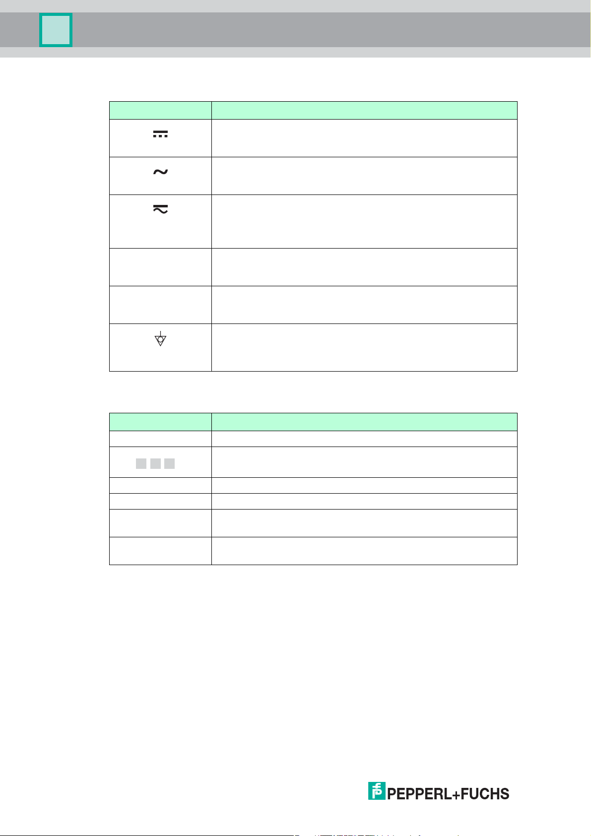
1.1.2 Electrical symbols
Symbol Meaning
)
*
Table 1.1
Direct current
A terminal to which DC voltage is applied or through which direct
current flows.
Alternating current
A terminal to which alternating voltage is applied or through which
alternating current flows.
Direct current and alternating current
• A terminal to which alternating voltage or DC voltage is applied.
• A terminal through which alternating current or direct current
flows.
Ground connection
A grounded terminal which, as far as the operator is concerned, is
grounded via a grounding system.
Protective ground connection
A terminal which must be connected to ground prior to establishing
any other connections.
Equipotential connection
A connection that has to be connected to the plant grounding
system: This may be a potential equalization line or a star grounding
system depending on national or company codes of practice.
1.1.3 Symbols in graphics
Symbol Meaning
1, 2, 3 ... Item numbers
,…,1. 2. 3.
A, B, C, ... Views
A-A, B-B, C-C, ... Sections
.
Table 1.2
Series of steps
Hazardous area
Indicates a hazardous area.
Safe area (non-hazardous area)
Indicates a non-hazardous location.
2014-10
8
Page 9
Pulscon LTC51
F
L
D
E
20 mA
100%
4mA
0%
LN
R
Function and system design
2 Function and system design
2.1 Measuring principle
2.1.1 Basic principles
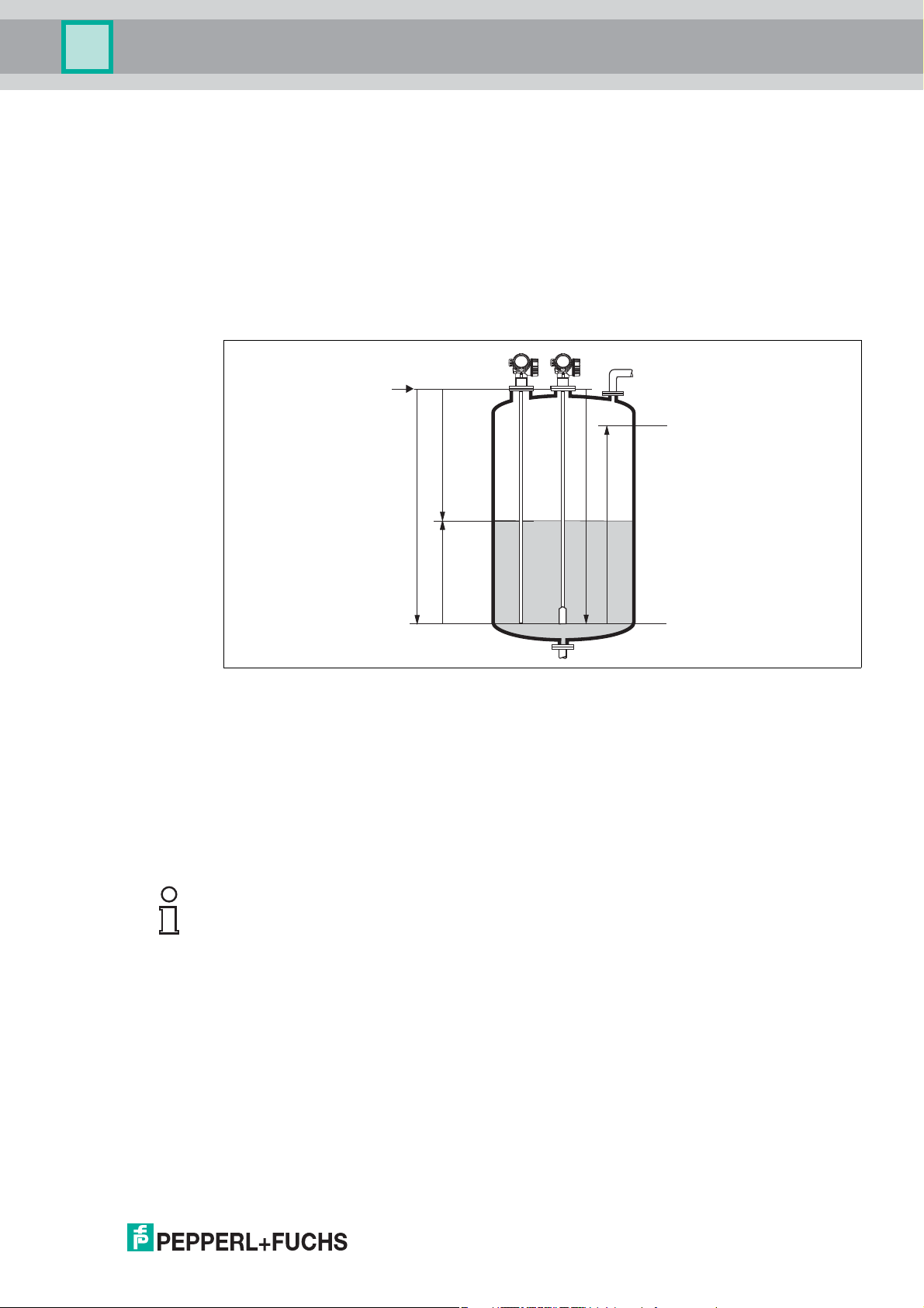
The device is a "downward-looking" measuring system that functions according to the ToF
method (ToF = Time of Flight). The distance from the reference point to the product surface is
measured. High-frequency pulses are injected to a probe and led along the probe. The pulses
are reflected by the product surface, received by the electronic evaluation unit and converted
into level information. This method is also known as TDR (Time Domain Reflectometry).
Figure 2.1 Parameters for level measurement with the guided radar
LN Probe length
D Distance
L Level
R Reference point of measurement
E Empty calibration (= zero)
F Full calibration (= span)
Note!
If, for rope probes, the DC value is less than 7, then measurement is not possible in the area of
the straining weight (0 to 250 mm from end of probe; lower blocking distance).
2.1.2 Dielectric constant
The dielectric constant (DC) of the medium has a direct impact on the degree of reflection of
the high frequency pulses. In the case of large DC values, such as for water or ammonia, there
is strong pulse reflection while, with low DC values, such as for hydrocarbons, weak pulse
reflection is experienced.
2014-10
9
Page 10

Pulscon LTC51
Function and system design
2.1.3 Input
The reflected pulses are transmitted from the probe to the electronics. There, a
microprocessor analyzes the signals and identifies the level echo which was generated by the
reflection of the high-frequency pulses at the product surface. This clear signal detection
system benefits from over 30 years' experience with pulse time-of-flight procedures.
The distance D to the product surface is proportional to the time of flight t of the impulse:
D = c x t / 2,
where c is the speed of light.
Based on the known empty distance E, the level L is calculated:
L = E – D
Note!
The reference point R of the measurement is located at the process connection.
See chapter 10.
The device possesses functions for interference echo suppression that can be activated by the
user. They guarantee that interference echoes from e. g. internals and struts are not
interpreted as level echoes.
2.1.4 Output
The device is preset at the factory to the probe length ordered so that in most cases only the
application parameters that automatically adapt the device to the measuring conditions need
to be entered. For models with a current output, the factory adjustment for zero point E and
span F is 4 mA and 20 mA, for digital outputs and the display module 0 % and 100 %. A
linearization function with max. 32 points, which is based on a table entered manually or semiautomatically, can be activated on site or via remote operation. This function allows the level to
be converted into units of volume or mass, for example.
2.2 Life cycle of the product
Engineering
• Universal measuring principle
• Measurement unaffected by medium properties
• Hardware and software developed according to SIL IEC 61508
Procurement
• Pepperl+Fuchs being the world market leader in level measurement guarantees asset
protection
• Worldwide support and service
10
Installation
• Special tools are not required
• Reverse polarity protection
• Modern, detachable terminals
• Main electronics protected by a separate connection compartment
2014-10
Page 11

Pulscon LTC51
Function and system design
Commissioning
• Fast, menu-guided commissioning in only 6 steps
• Plain text display in national languages reduces the risk of error or confusion
• Direct local access of all parameters
• Short instruction manual at the device
Operation
• Multi-echo tracking: Reliable measurement through self-learning echo-search algorithms
taking into account the short-term and long-term history in order to check the found echoes
for plausibility and to suppress interference echoes.
• Diagnostics in accordance with NAMUR NE 107
Maintenance
• HistoROM: Data backup for instrument settings and measured values
• Exact instrument and process diagnosis to assist fast decisions with clear details
concerning remedies
• Intuitive, menu-guided operating concept in national languages saves costs for training,
maintenance and operation
• Cover of the electronics compartment can be opened in hazardous areas
Retirement
• Order code translation for subsequent models
• RoHS-conforming (Restriction of certain Hazardous Substances), unleaded soldering of
electronic components
• Environmentally sound recycling concept
2014-10
11
Page 12
Pulscon LTC51
Function and system design
2.3 Measuring system
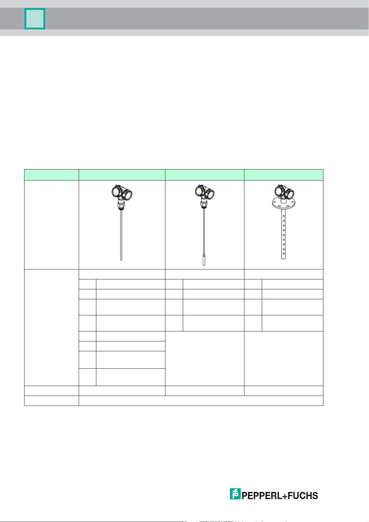
2.3.1 General notes on probe selection
• Normally use rod probes for liquids. Rope probes are used in liquids for measuring ranges
> 10 m (33 ft) and with restricted ceiling clearance which does not allow the installation of
rigid probes.
• Coax probes are suited to liquids with viscosities of up to approx. 500 cst. Coax probes
can measure most liquefied gases, as of a dielectric constant of 1.4. Moreover, installation
conditions, such as nozzles, tank internal fittings etc., have no effect on the measurement
when a coax probe is used. A coax probe offers maximum EMC safety when used in
plastic tanks.
Probe selection
The various types of probe in combination with the process connections are suitable for the
following applications
1
:
Type of probe Rod probe Rope probe Coax probe
Feature "Probe" Option Option Option
1 8 mm (316L) 2 4 mm (316) 4 ... mm (316L)
5 1/3 in (316L) 3 1/6 in (316) G ... inch (316L)
8 12 mm (316L) E 4 mm (316) with
H ... mm (Alloy C)
center rod
9 1/2 in (316L) F 1/6 in (316) with
K ... inch (Alloy C)
center rod
6 12 mm (Alloy C)
7 1/2 in (Alloy C)
A
16 mm (316L) divisible
C
B
0.63 in (316L) divisible
D
Max. probe length 10 m (33 ft)
b
45 m (148 ft) 6 m (20 ft)
For application Level measurement in liquids
Table 2.1
a
a
Multiple punched for process connections G1-1/2 in or flange
b
Maximum probe length for indivisible rod probes: 4 m (13 ft)
1
If required, rod and rope probes can be replaced. They are secured with Nord-Lock washers or a thread coating.
For further information on service and spare parts please contact the Pepperl+Fuchs service.
12
2014-10
Page 13

Pulscon LTC51
Input
3Input
3.1 Measured variable
The measured variable is the distance between the reference point and the product surface.
Subject to the empty distance entered E the level is calculated.
Alternatively, the level can be converted into other variables (volume, mass) by means of
linearization (32 points).
3.2 Measuring range
The following table describes the media groups and the possible measuring range as a
function of the media group.
Pulscon LTC51
Media
group
1 1.4 ... 1.6 condensed gases,
2 1.6 ... 1.9 • liquefied gas,
3 1.9 ... 2.5 mineral oils, fuels • one-piece: 4 m (13 ft)
4 2.5 ... 4 • benzene, styrene,
5 4 ... 7 • chlorobenzene,
6 >7 •aqueous
Table 3.1
DC (r) Typical liquids Measuring range
bare metallic
rod probes
e. g. N2, CO
e. g. propane
•solvent
•Freon
•palm oil
toluene
•furan
• naphthalene
chloroform
• cellulose spray
• isocyanate,
aniline
solutions
•alcohols
• ammonia
2
on request 6 m (20 ft)
• one-piece: 4 m (13 ft)
• divisible: 10 m (33 ft)
• divisible: 10 m (33 ft)
• one-piece: 4 m (13 ft)
• divisible: 10 m (33 ft)
• one-piece: 4 m (13 ft)
• divisible: 10 m (33 ft)
• one-piece: 4 m (13 ft)
• divisible: 10 m (33 ft)
bare metallic
rope probes
15 ... 22 m
(49 ... 72 ft)
22 ... 32 m
(72 ... 105 ft)
32 ... 42 m
(105 ... 138 ft)
42 ... 45 m
(138 ... 148 ft)
45 m (148 ft) 6 m (20 ft)
coax probes
6 m (20 ft)
6 m (20 ft)
6 m (20 ft)
6 m (20 ft)
Note!
Reduction of the max. possible measuring range through buildup, above all of moist products.
Due to the high diffusion rate of ammonia it is recommended with gas-tight bushing for
measurements in this medium.
2014-10
13
Page 14
Pulscon LTC51
F
UB
E
100%
0%
LN
R
SD
Input
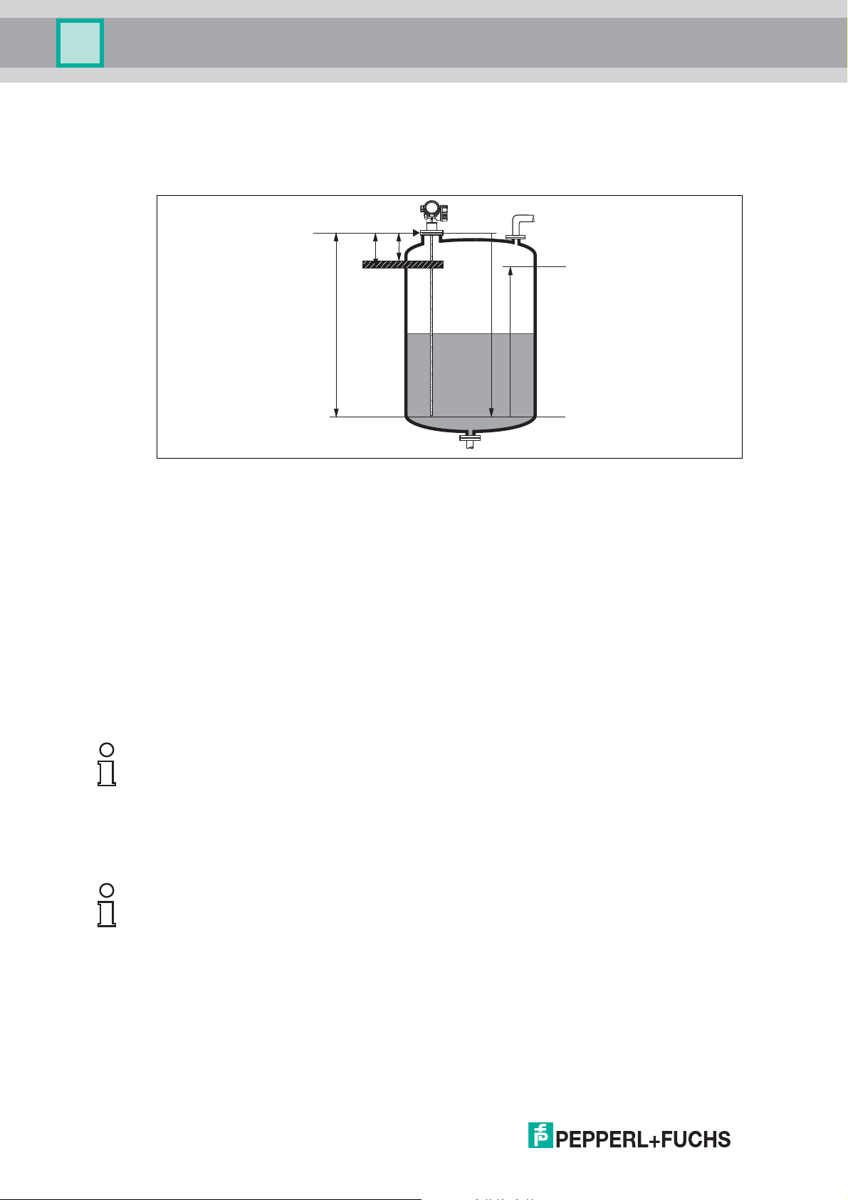
3.3 Blocking distance
The upper blocking distance (= UB) is the minimum distance from the reference point of the
measurement (mounting flange) to the maximum level.
Figure 3.1 Definition of blocking distance and safety distance
R Reference point of measurement
LN Probe length
UB Upper blocking distance
E Empty calibration (= zero)
F Full calibration (= span)
SD Safety distance
Blocking distance (factory setting):
• with coax probes: 0mm(0in)
• with rod and rope probes up to 8 m (26 ft): 200 mm (8 in)
• with rod and rope probes exceeding a length of 8 m (26 ft): 0.025 x (length of probe)
Note!
The specified blocking distances are preset on delivery. Depending on the application these
settings can be changed.
For rod and rope probes and for media with DC > 7 (or generally for stilling well/bypass
applications) the blocking distance may be reduced to 100 mm (4 in).
Within the blocking distance, a reliable measurement can not be guaranteed.
Note!
A safety distance SD can be defined in addition to the blocking distance. A warning is
generated if the level rises into this safety distance.
3.4 Measuring frequency spectrum
100 MHz to 1.5 GHz
14
2014-10
Page 15
Pulscon LTC51
Output
4Output
4.1 Output signal
HART
Signal coding FSK ±0.5 mA over currency signal
Data transmission rate 1200 Baud
Galvanic isolation Yes
Table 4.1
PROFIBUS PA
Signal coding Manchester Bus Powered (MBP)
Data transmission rate 31.25 kBit/s, voltage mode
Galvanic isolation Yes
Table 4.2
Switch output
Note!
For HART devices, the switch output is available as an option. See product structure, feature
"Electrical Output", option ID. Devices with PROFIBUS PA always have a switch output.
Switch output
Function Open collector switching output
Switching behavior Binary (conductive or non-conductive), switches when the
programmable switch point is reached
Failure mode non-conductive
Electrical connection values U = 10.4 ... 35 V DC, I = 0 ... 40 mA
Internal resistance RI < 880
The voltage drop at this internal resistance has to be taken
into account on planning the configuration. For example, the
resulting voltage at a connected relay must be sufficient to
switch the relay.
Insulation voltage floating, Insulation voltage 1350 V DC to power supply and
Switch point freely programmable, separately for switch-on and switch-off
Switching delay freely programmable from 0 to 100 s, separately for switch-
Number of switching cycles corresponds to the measuring cycle
Signal source
device variables
Number of switching cycles unlimited
Table 4.3
500 V AC to ground
point
on and switch-off point
• Level linearized
•Distance
• Terminal voltage
• Electronic temperature
• Relative echo amplitude
• Diagnostic values, Advanced diagnostics
2014-10
15
Page 16

Pulscon LTC51
Output
4.2 Signal on alarm
Depending on the interface, failure information is displayed as follows:
• Current output (for HART devices)
• Fail-safe mode selectable (in accordance with NAMUR Recommendation NE 43):
Minimum alarm: 3.6 mA
Maximum alarm (= factory setting): 22 mA
• Fail-safe mode with user-selectable value: 3.59 ... 22.5 mA
•Local display
• Status signal (in accordance with NAMUR Recommendation NE 107)
• Plain text display
• Operating tool via digital communication (HART, PROFIBUS PA) or service interface (CDI)
• Status signal (in accordance with NAMUR Recommendation NE 107)
• Plain text display
4.3 Linearization
The linearization function of the device allows the conversion of the measured value into any
unit of length or volume. Linearization tables for calculating the volume in cylindrical tanks are
pre-programmed. Other tables of up to 32 value pairs can be entered manually or semiautomatically.
4.4 Galvanic isolation
All circuits for the outputs are galvanically isolated from each other.
16
2014-10
Page 17

Pulscon LTC51
Output
4.5 Protocol-specific data
HART
Manufacturer ID 17 (0x11)
Device type ID 0x34
HART specification 6.0
Device description files
(DTM, DD)
HART load Min. 250
HART device variables The measured values can be freely assigned to the device
Supported functions •Burst mode
Table 4.4
Information and files under:
• www.pepperl-fuchs.com
• www.hartcomm.org
variables.
Measured values for PV (primary variable)
• Level linearized
•Distance
• Electronic temperature
• Relative echo amplitude
Measured values for SV, TV, FV (second, third and fourth
variable)
• Level linearized
•Distance
• Terminal voltage
• Electronic temperature
• Absolute echo amplitude
• Relative echo amplitude
• Calculated DC
• Additional transmitter status
Wireless HART data
Minimum start-up voltage 11.4 V
Start-up current 3.6 mA
Start-up time 15 s
Minimum operating voltage 11.4 V
Multidrop current 3.6 mA
Set-up time 1 s
Table 4.5
2014-10
17
Page 18

Pulscon LTC51
Output
PROFIBUS PA
Manufacturer ID 93 (5D HEX)
Ident number 0E3B HEX
Profile version 3.02
GSD file Information and files under:
GSD file version
Output values Analog Input:
Input values Analog Output:
Supported functions • Identification & Maintenance
Table 4.6
• www.pepperl-fuchs.com
•www.profibus.org
• Level linearized
•Distance
• Terminal voltage
• Electronic temperature
• Absolute echo amplitude
• Relative echo amplitude
• Calculated DC
Digital Input:
• Extended diagnostic blocks
• Status output PFS Block
• Analog value from PLC (for sensor block external
pressure and temperature)
• Analog value from PLC to be indicated on the display
Digital Output:
• Extended diagnostic block
• Level limiter
• Sensor block measurement on
• Sensor block save history on
• Status output
Simple device identification via control system and
nameplate
• Automatic Ident Number Adoption
GSD compatibility mode with respect to the previous
device
• Physical Layer Diagnostics
Installation check of the PROFIBUS segment via
terminal voltage and telegram monitoring
•PROFIBUS Up-/Download
Up to 10 times faster reading and writing of parameters
via PROFIBUS Up-/Download
•Condensed Status
Simple and self-explanatory diagnostic information due
to categorization of diagnostic messages
18
2014-10
Page 19
Pulscon LTC51
+
–
4 ... 20 mA
5412
7
8
3
+
–
1
+
2
4...20mA
HART
10
mm
2- wire
leve
l
4-20
mA
4-20
mA
HA
RT
[21]
open
-
6
~
Power supply
5 Power supply
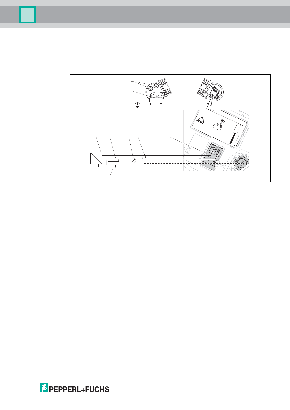
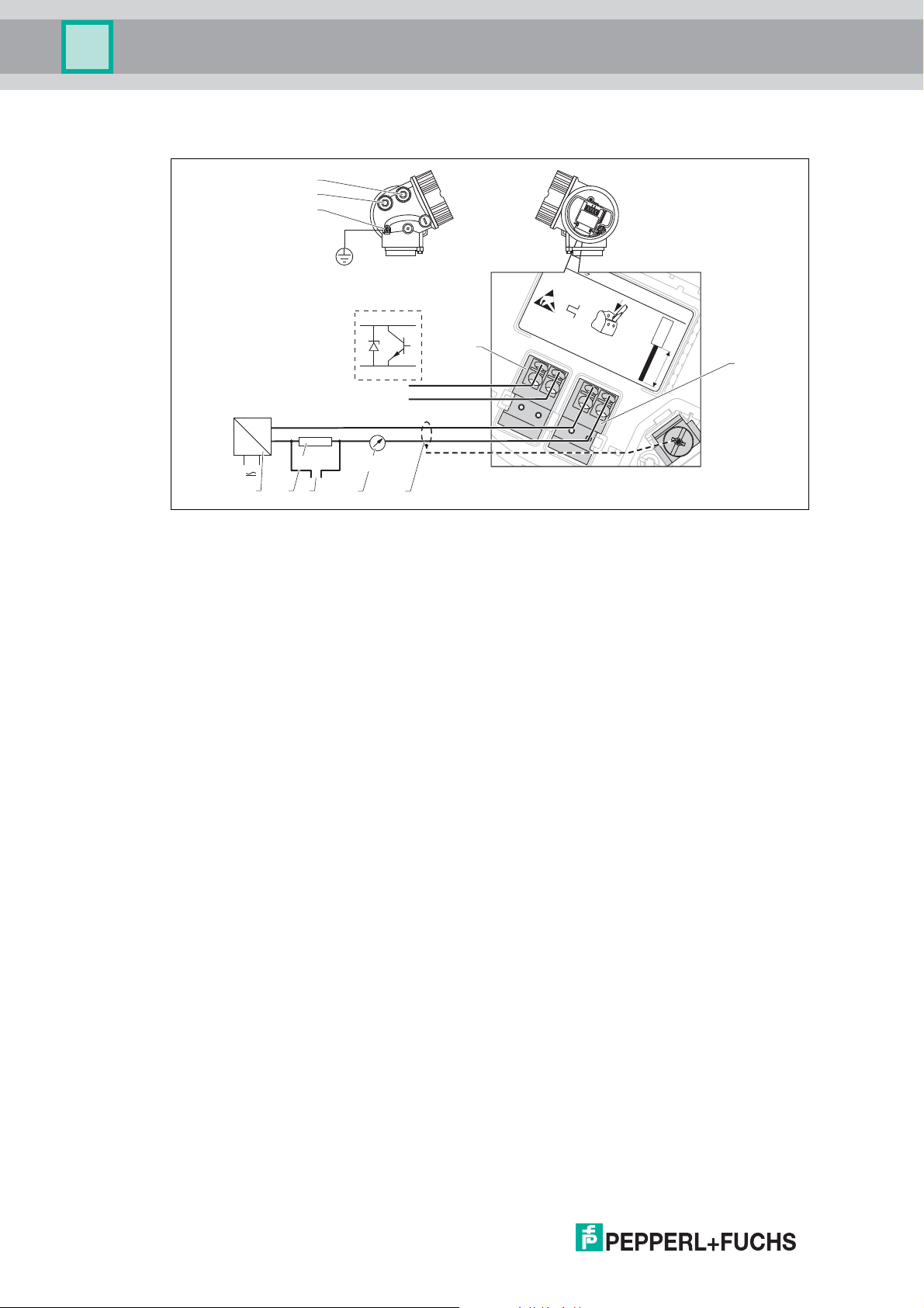
5.1 Terminal assignment
2-wire: 4 ... 20 mA HART
Figure 5.1 Terminal assignment 2-wire; 4 ... 20 mA HART
1 Active barrier with power supply (e. g. KCD2-STC-Ex1): observe terminal voltage
2 HART communication resistor ( 250 ): observe maximum load
3 Connection for optional field communicator
4 Analog display device: observe maximum load
5 Cable screen; observe cable specification
6 4 ... 20 mA HART (passive): terminals 1 and 2
7 Terminal for potential equalization line
8 Cable entry
2014-10
19
Page 20
Pulscon LTC51
1
+
2
4...20 mA
HART
10 mm
2- wire
4-20 mA PFS
HA
RT
[02/03
]
ope
n
-
1
+
2
-
3
+
4
-
10
9
8
7
+
-
23
4
6
5
1
4 ... 20 mA
≥ 250 Ω
3+
4-
+
–
Power supply
2-wire: 4 ... 20mA HART, switch output
Figure 5.2 Terminal assignment 2-wire; 4 ... 20mA HART, switch output
1 Active barrier with power supply (e. g. KCD2-STC-Ex1): observe terminal voltage
2 HART communication resistor ( 250 ): observe maximum load
3 Connection for optional field communicator
4 Analog display device: observe maximum load
5 Cable screen; observe cable specification
6 4 ... 20 mA HART (passive): terminals 1 and 2
7 Switch output (open collector): terminals 3 and 4
8 Terminal for potential equalization line
9 Cable entry for 4 ... 20 mA HART line
10 Cable entry for switch output line
20
2014-10
Page 21
Pulscon LTC51
1
3
+
+
2
4
4...20mA
HART
4...20mA
10 mm
2- wire
level
4-20 mA 4-20 mA
HA
RT
[04/05]
open
-
-
10
13
12
11
+
+
-
-
1
2
3
9
586
74
4
+
–
+
–
4 ... 20 mA
4 ... 20 mA
Power supply
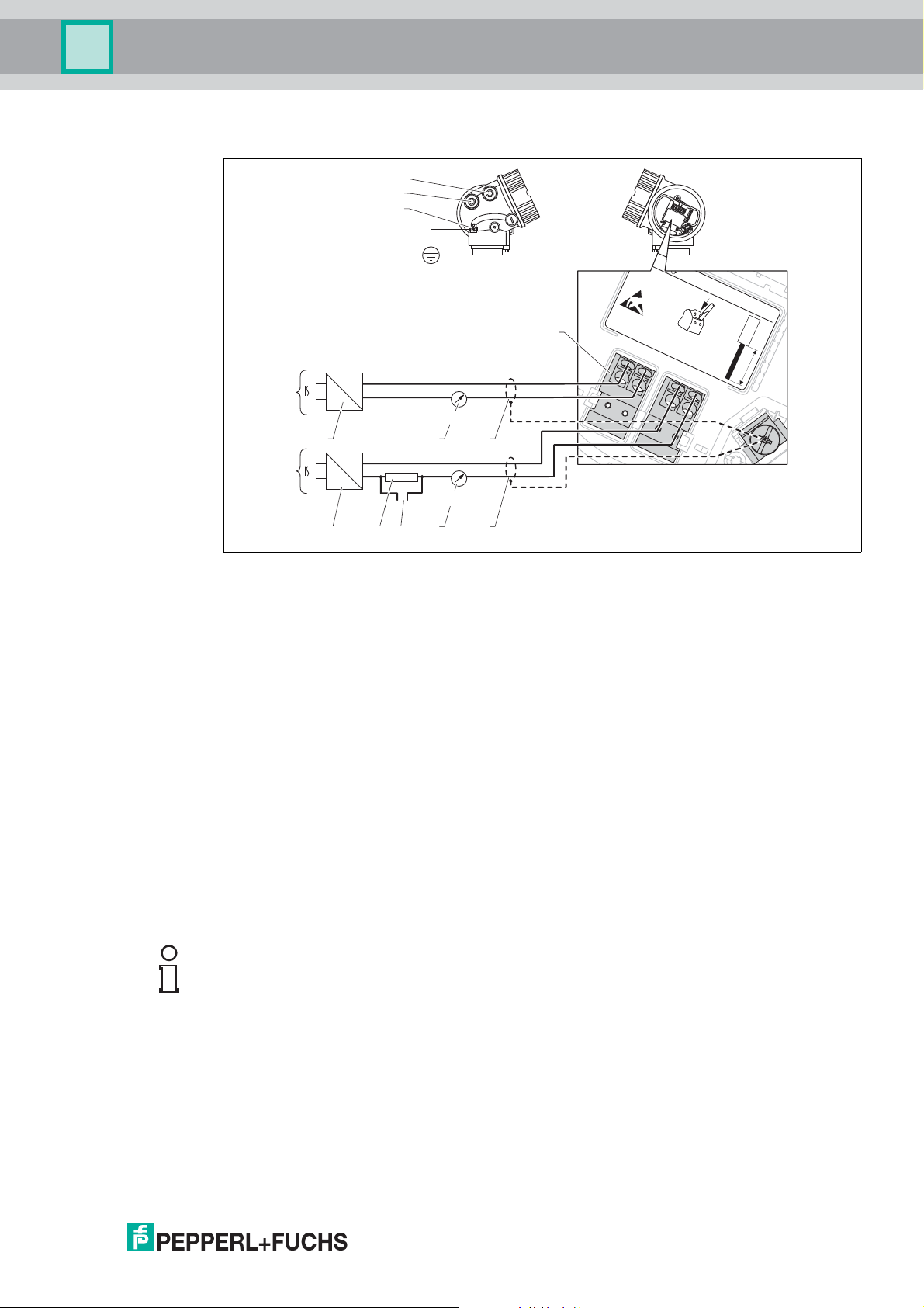
2-wire: 4 ... 20 mA HART, 4 ... 20 mA
Figure 5.3 Terminal assignment 2-wire, 4 ... 20 mA HART, 4 ... 20 mA
1 Connection current output 2
2 Connection current output 1
3 Supply voltage for current output 1 (e. g. KCD2-STC-Ex1); observe terminal voltage
4 Cable screen; observe cable specification
5 HART communication resistor ( 250 ): observe maximum load
6 Connection for optional field communicator
7 Analog display device; observe maximum load
8 Analog display device; observe maximum load
9 Supply voltage for current output 2 (e. g. KCD2-STC-Ex1); observe terminal voltage
10 Current output 2: terminals 3 and 4
11 Terminal for the potential equalization line
12 Cable entry for current output 1
13 Cable entry for current output 2
Note!
This version is also suited for single-channel operation. In this case, current output 1
(terminals 1 and 2) must be used.
2014-10
21
Page 22
Pulscon LTC51
3
1
+
L+
4
2
4...20 mA
HA
RT
10.4...48V=
10
mm
2- wire
4-20 mA
HA
RT
[08
]
ope
n
-
L-
13
12
11
910
+
-
23
4
6
7
8
5
1
4 ... 20 mA
250Ω
Power supply
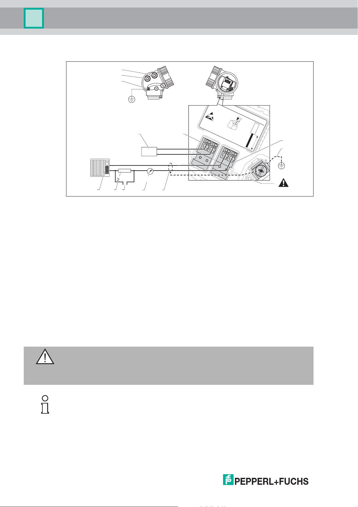
4-wire: 4 ... 20 mA HART (10.4 ... 48 V DC)
Figure 5.4 Terminal assignment 4-wire; 4 ... 20mA HART (10.4 ... 48 V DC)
1 Evaluation unit, e. g. PLC
2 HART communication resistor ( 250 ): observe maximum load
3 Connection for optional field communicator
4 Analog display device: observe maximum load
5 Signal cable including screening (if required), observe cable specification
6 Protective connection; do not disconnect!
7 Protective earth, observe cable specification
8 4 ... 20 mA HART (active): terminals 3 and 4
9 Supply voltage: terminals 1 and 2
10 Supply voltage: Observe terminal voltage, observe cable specification
11 Terminal for potential equalization
12 Cable entry for signal line
13 Cable entry for power supply
Warning!
To ensure electrical safety:
• Do not disconnect the protective connection (6).
• Disconnect the supply voltage before disconnecting the protective earth (7).
Note!
Connect protective earth to the internal ground terminal (7) before connecting the supply
voltage. If necessary, connect the potential matching line to the external ground terminal (11).
22
2014-10
Page 23

Pulscon LTC51
Power supply
Note!
In order to ensure electromagnetic compatibility (EMC): Do not only ground the device via the
protective earth conductor of the supply cable. Instead, the functional grounding must also be
connected to the process connection (flange or threaded connection) or to the external ground
terminal.
Note!
An easily accessible power switch must be installed in the proximity of the device. The power
switch must be marked as a disconnector for the device (IEC/EN 61010).
2014-10
23
Page 24

Pulscon LTC51
3
1
+
L
4
2
4...20 mA
HA
RT
90...2
53
V~
10
mm
2- wire
4-20 mA
HA
RT
[09
]
ope
n
-
N
13
12
11
910
+
-
23
4
6
7
8
5
1
4 ... 20 mA
≥ 250Ω
Power supply
4-wire: 4 ... 20 mA HART (90 ... 253 V AC)
Figure 5.5 Terminal assignment 4-wire; 4 ... 20 mA HART (90 ... 253 V AC)
1 Evaluation unit, e. g. PLC
2 HART communication resistor ( 250 ): observe maximum load
3 Connection for optional filed communicator
4 Analog display device: observe maximum load
5 Signal cable including screening (if required), observe cable specification
6 Protective connection; do not disconnect!
7 Protective earth, observe cable specification
8 4 ... 20 mA HART (active): terminals 3 and 4
9 Supply voltage: terminals 1 and 2
10 Supply voltage: observe terminal voltage, observe cable specification
11 Terminal for potential equalization
12 Cable entry for signal line
13 Cable entry for power supply
Warning!
To ensure electrical safety:
• Do not disconnect the protective connection (6).
• Disconnect the supply voltage before disconnecting the protective earth (7).
Note!
Connect protective earth to the internal ground terminal (7) before connecting the supply
voltage. If necessary, connect the potential matching line to the external ground terminal (11).
24
2014-10
Page 25

Pulscon LTC51
Power supply
Note!
In order to ensure electromagnetic compatibility (EMC): Do not only ground the device via the
protective earth conductor of the supply cable. Instead, the functional grounding must also be
connected to the process connection (flange or threaded connection) or to the external ground
terminal.
Note!
An easily accessible power switch must be installed in the proximity of the device. The power
switch must be marked as a disconnector for the device (IEC/EN 61010).
2014-10
25
Page 26
Pulscon LTC51
1
1
+
+
2
2
PA
[06/07]
-
-
1
3
+
+
2
4
PA
10 mm
2- wire
level
4-20 mA PFS
[26/27]
open
-
-
4
1
2
3
5
3+
4-
Power supply
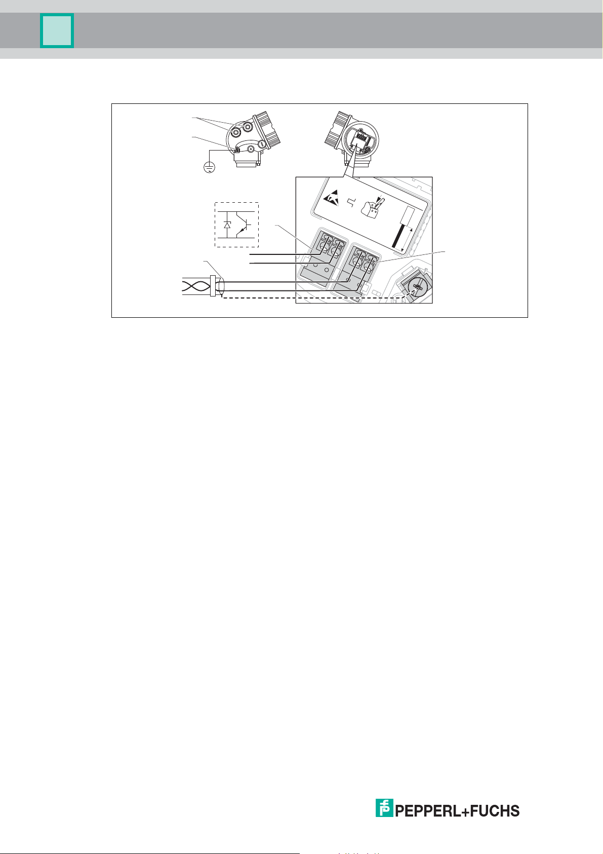
PROFIBUS PA
Figure 5.6 Terminal assignment PROFIBUS PA
1 Cable screen: observe cable specifications
2 Switch output (open collector): terminals 3 and 4
3 Connection PROFIBUS PA: terminals 1 and 2
4 Terminal for potential equalization line
5 Cable entries
26
2014-10
Page 27
Pulscon LTC51
Power supply
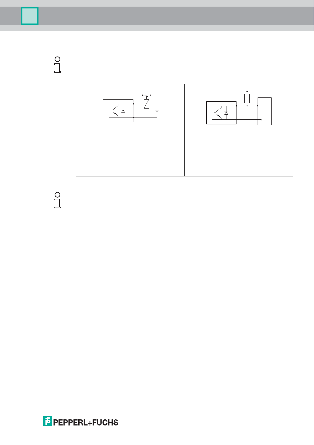
Connection examples for the switch output
Note!
For HART devices, the switch output is available as an option. See product structure, feature
"Electrical Output", option ID. Devices with PROFIBUS PA always have a switch output.
3+
4-
+
1
+
-
3+
4-
2
Connection of a relay
Suitable relays (examples):
• Solid-state relay: Phoenix Contact OV-
Connection of a digital input
1 Pull-up resistor
2 Digital input
24DC/480AC/5 with mounting rail
connector UMK-1 OM-R/AMS
• Electromechanical relay: Phoenix
Contact PLC-RSC-12DC/21
Table 5.1
Note!
For optimum interference immunity we recommend to connect an external resistor (internal
resistance of the relay or Pull-up resistor) of < 1000 .
2014-10
27
Page 28
Pulscon LTC51
Stromausgang1
Relais1
Stromausgang2
Stromausgang3
Relais2Relais2
versorgungversorgung
EingangEingang
1
2
3
4
5
6
7
8
9
11
12
13
14
15
19
20
21
16
17
18
22
23
24
24V DC
10
HART Loop Converter
HART
+
-
+
Current output 1
Relay 1
Current output 2
Current output 3
Relay 2
Power
supply
Input
Auxiliary energy
HART
ESC
OK
KFD2-HLCEx1.D.2W
RS232
PWR
ERR
1 2
OUT
19 21
15
9
13
7
20
14
8
2
2
24
18
12
16
10
23
17
11
1
3
2 4
6
5
Power supply
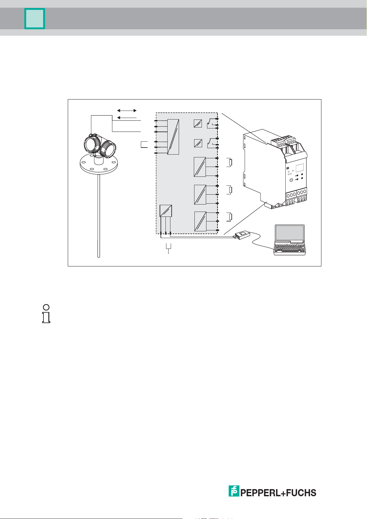
5.2 HART Loop Converter KFD2-HLC-Ex1.D.**
The dynamic variables of the HART protocol can be converted into individual 4 to 20 mA
sections using the HART loop converter KFD2-HLC-Ex1.D.**. The variables are assigned to
the current output and the measuring ranges of the individual parameters are defined in the
KFD2-HLC-Ex1.D.**.
28
Figure 5.7 Connection example KFD2-HLC-Ex1.D.**: passive 2-wire device and current outputs
The HART loop converter KFD2-HLC-Ex1.D.** can be acquired.
Note!
Additional documentation: see data sheets.
connected as power source
2014-10
Page 29
Pulscon LTC51
21
3
4
2
1
4
3
Power supply
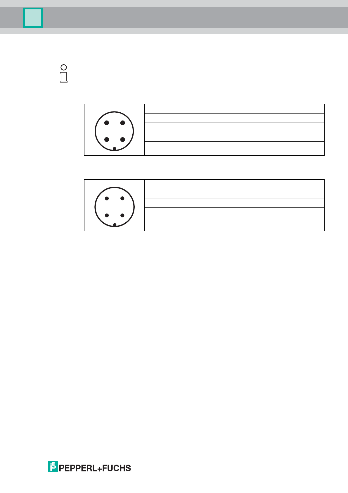
5.3 Device plug connectors
Note!
For the versions with fieldbus plug connector (M12 or 7/8 in), the signal line can be connected
without opening the housing.
Pin assignment of the M12 plug connector
Pin Meaning
1 Signal +
2 not connected
3 Signal 4 Ground
Table 5.2
Pin assignment of the 7/8 in plug connector
Table 5.3
Pin Meaning
1 Signal 2 Signal +
3 not connected
4 Screen
2014-10
29
Page 30
Pulscon LTC51
R [Ω]
[V]U
0
10
11.5 22.5
20 30 35
0
500
R [Ω]
[V]U
0
10
13.5 24.5
20 30
0
500
Power supply
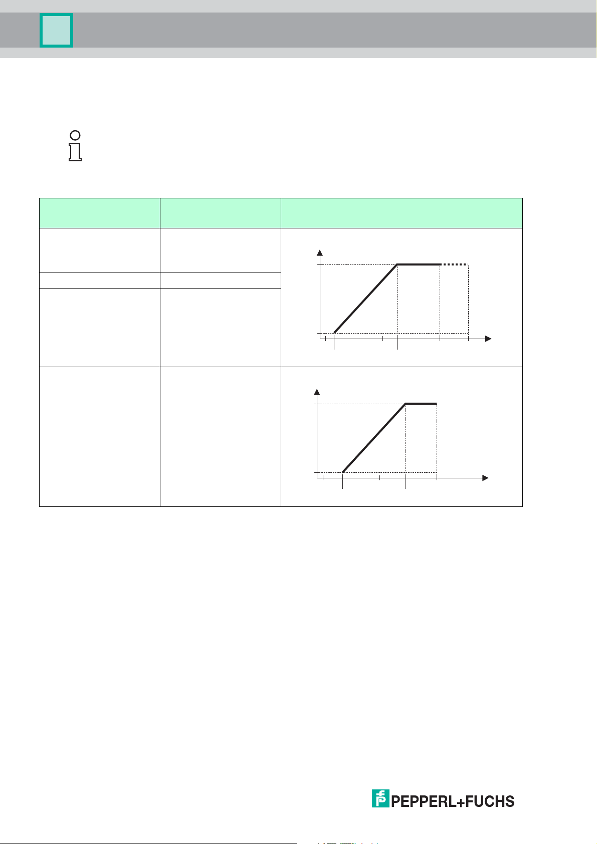
5.4 Power supply
An external power supply is required.
Note!
Various supply units can be ordered from Pepperl+Fuchs: see chapter 14.4.
2-wire, 4 ... 20 mA HART, passive
Approval
•Non-Ex
•ExnA
•CSAGP
•Exic 11.5 ... 32 V
•Exia/IS 11.5 ... 30 V
•Exd/XP
•Exic(ia)
• Ex tD/DIP
a
Terminal voltage U at the
device
11.5 ... 35 V
13.5 ... 30 V
1
Maximum load R, depending on the supply voltage
at the supply unit
U
0
b
c
d
e
Table 5.4
a
Feature "Approval" of the product structure
b
For ambient temperatures Ta -30 °C (-22 °F) a minimum voltage of 14 V is required for the startup of the device at the
MIN error current (3.6 mA). The startup current can be parametrized. If the device is operated with a fixed current I 4.5 mA
(HART multidrop mode), a voltage of U 11.5 V is sufficient throughout the entire range of ambient temperatures.
c
For ambient temperatures Ta -30 °C (-22 °F) a minimum voltage of 14 V is required for the startup of the device at the
MIN error current (3.6 mA). The startup current can be parametrized. If the device is operated with a fixed current I 4.5 mA
(HART multidrop mode), a voltage of U 11.5 V is sufficient throughout the entire range of ambient temperatures.
d
For ambient temperatures Ta -30 °C (-22 °F) a minimum voltage of 14 V is required for the startup of the device at the
MIN error current (3.6 mA). The startup current can be parametrized. If the device is operated with a fixed current I 4.5 mA
(HART multidrop mode), a voltage of U 11.5 V is sufficient throughout the entire range of ambient temperatures.
e
For ambient temperatures Ta -20 °C (-4 °F) a minimum voltage of 16 V is required for the startup of the device at the MIN error
current (3.6 mA).
1
Feature "Electrical Output" of the product structure, option IH
30
2014-10
Page 31

Pulscon LTC51
R [Ω]
U0[V]
10
12 23
20 30 35
0
500
Power supply
1
Approval
a
•Non-Ex
2-wire; 4 ... 20 mA HART, switch output
Terminal voltage U at the
device
12 ... 35 V
b
Maximum load R, depending on the supply voltage
at the supply unit
U
0
•ExnA
•ExnA(ia)
•Exic
•Exic(ia)
•Exd(ia)/XP
•Exta/DIP
•CSAGP
•Exia/IS
12 ... 30 V
c
• Ex ia + Ex d(ia)/IS + XP
Table 5.5
a
Feature "Approval" of the product structure
b
For ambient temperatures Ta -30 °C (-22 °F) a minimum voltage of 14 V is required for the startup of the device at the
MIN error current (3.6 mA).
c
For ambient temperatures Ta -30 °C (-22 °F) a minimum voltage of 14 V is required for the startup of the device at the
MIN error current (3.6 mA).
2014-10
1
Feature "Electrical Output" of the product structure, option ID
31
Page 32

Pulscon LTC51
R [Ω]
[V]U
0
10
13.5 24.5
20 30
0
500
R [Ω]
U0[V]10
12 23
20 30
0
500
Power supply
2-wire; 4 ... 20 mA HART, 4 ... 20 mA
Approval
all Channel 1:
a
Terminal voltage U at the
device
13.5 ... 30 V
Channel 2:
12 ... 30 V
1
Maximum load R, depending on the supply voltage
at the supply unit
U
0
b
Table 5.6
a
Feature "Approval" of the product structure
b
For ambient temperatures Ta -30°C (-22 °F) a minimum voltage of 16 V is required for the startup of the device at the
MIN error current (3.6 mA).
Polarity reversal protection yes
Admissible residual ripple at f = 0 to 100 Hz USS<1V
Admissible residual ripple at
USS<10mV
f = 100 to 10000 Hz
Table 5.7
1
Feature "Electrical output" of the product structure, option IE
2014-10
32
Page 33

Pulscon LTC51
Power supply
4-wire, 4 ... 20 mA HART, active
Electrical Output
AH: 4-wire 90 ... 253 V AC;
4...20mA HART
DH: 4-wire 10.4 ... 48 V DC;
4...20mAHART
Table 5.8
a
Feature "Electrical Output" the product structure
PROFIBUS PA
Electrical Output
PA: 2-wire; PROFIBUS PA,
switch output
Table 5.9
a
Terminal voltage U Maximum load R
90 ... 253 V AC (50 ... 60 Hz),
500
max
overvoltage category II
10.4 ... 48 V DC
a
Approval
•Non-Ex
b
Terminal voltage
9...32V
c
•ExnA
•ExnA(ia)
•Exic
•Exic(ia)
•Exd(ia)/XP
•Exta/DIP
•CSAGP
•Exia/IS
9...30V
d
• Ex ia + Ex d(ia)/IS + XP
a
Feature "Electrical Output" the product structure
b
Feature "Approval" of the product structure
c
Input voltages up to 35 V will not spoil the device.
d
Input voltages up to 35 V will not spoil the device.
Polarity sensitive no
FISCO/FNICO compliant according to
IEC 60079-27
Table 5.10
yes
2014-10
33
Page 34

Pulscon LTC51
Power supply
5.5 Power consumption
Electrical output
IH: 2-wire; 4 ... 20 mA HART <0.9W
ID: 2-wire; 4 ... 20 mA HART, switch output <0.9W
IE: 2-wire; 4 ... 20 mA HART, 4 ... 20 mA <2x0.7W
AH: 4-wire 90 ... 253 V AC; 4 ... 20 mA HART 6VA
DH: 4-wire 10.4 ... 48 V DC; 4 ... 20 mA HART 1.3 W
Table 5.11
a
Feature "Electrical Output" of the product structure
a
5.6 Current consumption
HART
Nominal current 3.6 ... 22 mA, the start-up current for
Breakdown signal (NAMUR NE 43) adjustable: 3.59 ... 22.5 mA
Table 5.12
PROFIBUS PA
Nominal current 14 mA
Error current FDE (Fault Disconnection Electronic) 0 mA
Table 5.13
Power consumption
multidrop mode can be parametrized (is set
to 3.6 mA on delivery)
5.7 Power supply failure
• Configuration is retained in the HistoROM (EEPROM).
• Error messages (incl. value of operated hours counter) are stored.
5.8 Potential equalization
No special measures for potential equalization are required.
Note!
If the device is designed for hazardous areas, observe the information in the documentation
"Safety Instructions" (SI, ZD).
5.9 Terminals
Plug-in spring terminals for wire cross-sections 0.5 ... 2.5 mm2(20 ... 14 AWG)
34
2014-10
Page 35

Pulscon LTC51
Power supply
5.10 Cable entries
Connection of power supply and signal line
To be selected in feature "Electrical Connection"
• Gland M20; material dependent on the approval:
• For Non-Ex, ATEX, IECEx, NEPSI Ex ia/ic:
plastics M20 x 1.5 for cable Ø5 ... 10 mm (0.2...0.39 in)
• For Dust-Ex, FM IS, CSA IS, CSA GP, Ex nA:
metal M20 x 1.5 for cable Ø7 ... 10 mm (0.28...0.39 in)
•For Exd:
No gland available
•Thread
•1/2 in NPT
•G1/2
• M20 × 1.5
• Plug M12/plug 7/8 in
Only available for Non-Ex, Ex ic, Ex ia
1
5.11 Cable specification
• Minimum cross-section: dependent on terminals: see chapter 5.9.
• For ambient temperature T
a
HART
• A normal device cable suffices if only the analog signal is used.
• A shielded cable is recommended if using the HART protocol. Observe grounding concept
of the plant.
• For 4-wire devices: Standard device cable is sufficient for the power line.
PROFIBUS PA
• Use a twisted, screened two-wire cable, preferably cable type A.
Note!
For further information on the cable specifications, see PNO Guideline 2.092 "PROFIBUS PA
User and Installation Guideline" and IEC 61158-2 (MBP).
5.12 Overvoltage protection
If the measuring device is used for level measurement in flammable liquids which requires the
use of overvoltage protection according to DIN EN 60079-14, standard for test procedures
60060-1 (10 kA, pulse 8/20 s), overvoltage protection has to be ensured by an external
overvoltage protection module.
60 °C(140°F): use cable for temperature T
+20K.
a
External overvoltage protection
For detailed information please refer to www.pepperl-fuchs.com
1
The material of the gland is dependent on the housing type; A3 (GT18, stainless steel housing): 316L (1.4404); A1
2014-10
(GT19, plastic housing) and A2 (GT20, aluminum housing): nickel-coated brass (CuZn).
35
Page 36

Pulscon LTC51
Performance characteristics
6 Performance characteristics
6.1 Reference operating conditions
• Temperature = + 24 °C(+75°F) ±5 °C(9°F)
• Pressure = 960 mbar abs. (14 psia) ±100 mbar (1.45 psi)
• Humidity = 60 % ±15 %
• Reflection factor 0.8 (water surface for coax probe, metal plate for rod and rope probe
with min.1 m (40 in) diameter)
• Flange for rod or rope probe 300 mm (12 in) diameter
• Distance to obstacles 1m(40in)
6.2 Maximum measured error
Typical data under reference operating conditions: DIN EN 61298-2, percentage values in
relation to the span.
Output: digital analog
Sum of non-linearity, non-
repeatability and hysteresis
Offset/Zero ±4mm(0.16in) 0.03 %
Table 6.1
a
Add error of the analogous value to the digital value.
If the reference conditions are not met, the offset/zero point arising from the mounting situation
may be up to ±12 mm (0.47 in) for rope and rod probes. This additional offset/zero point can be
compensated for by entering a correction (parameter "level correction") during commissioning.
• Measuring distance up to15 m (49 ft):
±2mm(0.08in)
• Measuring distance > 15 m (49 ft):
±10 mm (0.39 in)
0.02 %
a
36
2014-10
Page 37

Pulscon LTC51
Performance characteristics
Differing from this, the following measuring error is present in the vicinity of the lower
probe end:
80 (3.15)
60 (2.36)
40 (1.57)
20 (0.79)
0
-20 (-0.79)
-40 (-1.57)
-60 (-2.36)
-80 (-3.15)
D
0
20 (0.79)
50 (1.97)
40 (1.57)
80 (3.15)
100 (3.94)
150 (5.91)
DC = 2
DC = 80
250 (9.84)
200 (7.87)
A
300 (11.8)
Figure 6.1 Measuring error at the end-of-probe for rod and coax probes
A Distance from probe end [mm (in)]
D Measuring error: sum of non-linearity, non-repeatability and hysteresis
DC Dielectric constant
D
80 (3.15)
60 (2.36)
40 (1.57)
20 (0.79)
0
-20 (-0.79)
-40 (-1.57)
-60 (-2.36)
-80 (-3.15)
0
20 (0.79)
50 (1.97)
100 (3.94)
DC = 80
150 (5.91)
200 (7.87)
A
300 (11.8)
250 (9.84)
Figure 6.2 Measuring error at the end-of-probe for rope probes
A Distance from probe end
D Measuring error: sum of non-linearity, non-repeatability and hysteresis
DC Dielectric constant
2014-10
37
Page 38

Pulscon LTC51
Performance characteristics
120 (4.72)
100 (3.94)
80 (3.15)
60 (2.36)
40 (1.57)
20 (0.79)
0
-20 (-0.79)
-40 (-1.57)
-60 (-2.36)
-80 (-3.15)
-100 (-3.94)
-120 (-4.72)
D
DC = 2
DC = 80
0
A
50 (1.97)
30 (0.79)
150 (5.91)
100 (3.94)
200 (7.87)
250 (9.84)
300 (11.8)
Figure 6.3 Measuring error at the end-of-probe for probes with a metallic centering disk
A Distance from probe end [mm (in)]
D Measuring error: sum of non-linearity, non-repeatability and hysteresis
DC Dielectric constant
Note!
If for rope probes the DC value is less than 7, then measurement is not possible in the area of
the straining weight (0 to 250 mm from end of probe; lower blocking distance).
38
2014-10
Page 39

Pulscon LTC51
2 mm
0 mm
- 2 mm
100 mm 200 mm
10 mm
- 10 mm
20 mm
- 20 mm
30 mm
- 30 mm
40 mm
- 40 mm
R
D
DC = 2
DC = 80
Performance characteristics
In the area of the upper probe end, the measuring error is as follows (rod/rope only):
Figure 6.4 Measuring error at the upper end of the probe
D Sum of non-linearity, non-repeatability and hysteresis
R Reference point of measurement
DC Dielectric constant
6.3 Resolution
• digital: 1 mm
•analog: 1 µA
6.4 Reaction time
The reaction time can be parametrized. The following step response times (as per
DIN EN 61298-2)
Level measurement
Probe length Sampling rate Step response time
<10m(33ft) 3.6 measurements/second < 0.8 s
< 40 m (131 ft) 2.7 measurements/second < 1 s
Table 6.2
1
are valid if the damping is switched off:
1
According to DIN EN 61209-2 the response time is the time which passes after a sudden change of the input
2014-10
signal until the output signal for the first time assumes 90 % of the steady-state value.
39
Page 40

Pulscon LTC51
Performance characteristics
6.5 Influence of ambient temperature
The measurements are carried out in accordance with EN 61298-3
• digital (HART, PROFIBUS PA): average T
For devices with remote sensor
±0.3 mm/10K (0.01 in/10 K) per1 m (3.3 ft) of the remote cable.
• analog (current output):
• zero point (4 mA): average T
• span (20 mA): average T
6.6 Influence of gas layer
High pressures reduce the propagation velocity of the measuring signals in the gas/vapor
above the fluid. This effect depends on the kind of gas/vapor and of its temperature. This
results in a systematic measuring error that gets bigger as the distance increases between the
reference point of the measurement (flange) and the product surface. The following table
illustrates this measured error for a few typical gases/vapors (with regard to distance; a
positive value means that too large a distance is being measured):
1
there is an additional offset of
=0.02%/10K
K
= 0.05 %/10 K
K
= 0.6 mm/10 K
K
Gas layer Temperature Pressure
°C °F 1 bar
(14.5 psi)
10 bar
(145 psi)
50 bar
(725 psi)
100 bar
(1450 psi)
200 bar
(2900 psi)
400 bar
(5800 psi)
Air 20 68 0.00 % 0.22 % 1.2 % 2.4 % 4.9 % 9.5 %
200 392 -0.01 % 0.13 % 0.74 % 1.5 % 3.0 % 6.0 %
400 752 -0.02 % 0.08 % 0.52 % 1.1 % 2.1 % 4.2 %
Hydrogen 20 68 -0.01 % 0.10 % 0.61 % 1.2 % 2.5 % 4.9 %
200 392 -0.02 % 0.05 % 0.37 % 0.76 % 1.6 % 3.1 %
400 752 -0.02 % 0.03 % 0.25 % 0.53 % 1.1 % 2.2 %
Table 6.3
Gas layer Temperature Pressure
Water
(saturated
steam)
°C °F 1 bar
(14.5 psi)
100 212 0.26 % – – – – – – –
120 248 0.23 % 0.50 % – – – – – –
2 bar
(29 psi)
5 bar
(72.5 psi)
10 bar
(145 psi)
20 bar
(290 psi)
50 bar
(725 psi)
100 bar
(1450 psi)
152 306 0.20 % 0.42 % 1.14 % – – – – –
180 356 0.17 % 0.37 % 0.99 % 2.10 % – – – –
212 414 0.15 % 0.32 % 0.86 % 1.79 % 3.9 % – – –
264 507 0.12 % 0.26 % 0.69 % 1.44 % 3.0 % 9.2 % – –
311 592 0.09 % 0.22 % 0.58 % 1.21 % 2.5 % 7.1 % 19.3 % –
366 691 0.07 % 0.18 % 0.49 % 1.01 % 2.1 % 5.7 % 13.2 % 76 %
Table 6.4
200 bar
(2900 psi)
40
1
Product structure: Feature "Probe design", option B)
2014-10
Page 41

Pulscon LTC51
Performance characteristics
6.7 Gas phase compensation with external pressure sensor (PROFIBUS PA)
PROFIBUS devices can receive the signal of an external pressure sensor through the bus and
use it to perform a pressure dependent time-of-flight correction. In the case of saturated steam
in the temperature range from 100 ... 350 °C (212 ... 662 °F), for example, the measuring error
of the distance measurement can be reduced by this method from up to 29 % (without
compensation) to less than 3 % (with compensation).
2014-10
41
Page 42

Pulscon LTC51
A
C
1
23
4
B
Mounting
7Mounting
7.1 Mounting requirements
7.1.1 Suitable mounting position
Figure 7.1 Mounting requirements
Mounting distances
• Distance (A) between wall and rod or rope probe:
• for smooth metallic walls: > 50 mm (2 in)
• for plastic walls: > 300 mm (12 in) to metallic parts outside the vessel
• for concrete walls: > 500 mm (20 in), otherwise the available measuring range may
be reduced.
• Distance (B) between rod or rope probe and internal fittings in the vessel: > 300 mm (12 in)
• Distance (C) from end of probe to bottom of the vessel:
• Rope probe: > 150 mm (6 in)
• Rod probe: > 10 mm (0.4 in)
Note!
For coax probes the distance to the wall and to internal fittings is arbitrary.
•Coax probe: > 10mm(0.4in)
2014-10
42
Page 43

Pulscon LTC51
Mounting
Additional conditions
• When mounting in the open, a weather protection cover (1) may be installed to protect the
device against extreme weather conditions.
• In metallic vessels: Preferably do not mount the probe in the center of the vessel (2), as this
would lead to increased interference echoes.
If a central mounting position can not be avoided, it is crucial to perform an interference
echo suppression (mapping) after the commissioning of the device.
• Do not mount the probe in the filling curtain (3).
• Avoid buckling the rope probe during installation or operation (e. g. through product
movement against silo wall) by selecting a suitable mounting location.
• Check the probe regularly for defects.
Note!
With suspended rope probes (probe end not fixed at the bottom) the distance between the
probe rope and internal fittings in the tank must not fall below 300 mm (12 in) during the entire
process. A sporadic contact between the probe weight and the cone of the vessel, however,
does not influence the measurement as long as the dielectric constant of the medium is at least
DC = 1.8.
Note!
When mounting the electronics housing into a recess (e. g. in a concrete ceiling), observe a
minimum distance of 100 mm (4 in) between the cover of the terminal compartment/electronics
compartment and the wall. Otherwise the connection compartment/electronics compartment is
not accessible after installation.
2014-10
43
Page 44

Pulscon LTC51
Mounting
7.1.2 Applications with restricted mounting space
Mounting with remote sensor
The device version with a remote sensor is suited for applications with restricted mounting
space. In this case the electronics housing is mounted at a separate position from which it is
easier accessible.
A
6 Nm
(4.42 lbf ft)
C
Figure 7.2
r = 100 (4)
min
6 Nm
(4.42 lbf ft)
A Angled plug at the probe
B Angled plug at the electronics housing
C Length of the remote cable as ordered
B
(4.42 lbf ft)
r = 100 (4)
min
6 Nm
C
6 Nm
(4.42 lbf ft)
44
• Product structure, feature "Probe Design": option B "Sensor remote, 3 m/9 ft cable"
• The remote cable is supplied with these device versions, minimum bending radius:
100 mm (4 in)
• A mounting bracket for the electronics housing is supplied with these device versions.
Mounting options:
•Wall mounting
• Pipe mounting; diameter: 42 to 60 mm (1-1/4 to 2 in)
• The connection cable has got one straight and one angled plug (90°). Depending on the
local conditions the angled plug can be connected at the probe or at the electronics
housing.
Note!
Probe, electronics and connection cable are adjusted to match each other. They are marked
by a common serial number. Only components with the same serial number shall be
connected to each other.
2014-10
Page 45

Pulscon LTC51
14 mm
14 mm
Mounting
Divisible probes
Figure 7.3
If there is little mounting space (distance to the ceiling), it is advisable to use divisible rod
probes (Ø16 mm).
• max. probe length 10 m (394 in)
• max. sideways capacity 30 Nm
• probes are separable several times with the following lengths of the individual parts:
•torque: 15Nm
•500mm(20in)
• 1000 mm (40 in)
2014-10
45
Page 46

Pulscon LTC51
v
L
N
L
d
Mounting
7.1.3 Notes on the mechanical load of the probe
Tensile load limit of rope probes
Feature "Probe" Probe Tensile load limit [kN]
Option 2, 3, E, F Rope 4 mm (1/6 in) 316 5
Table 7.1
Bending strength of rod probes
Feature "Probe" Probe Bending strength [Nm]
Option 1, 5 Rod 8 mm (1/3 in) 316L 10
Option 8, 9 Rod 12 mm (1/2 in) 316L 30
Option 6, 7 Rod 12 mm (1/2 in) AlloyC 30
Option A, B, C, D Rod 16 mm (0.63 in) 316L
divisible
Table 7.2
30
Bending load (torque) through fluid flow
The formula for calculating the bending torque M impacting on the probe:
M = cw × / 2 × v2 × d × L × (LN - 0.5 × L)
with:
c
: friction factor
w
[kg/m
v [m/s]: Velocity of the medium perpendicular to the probe rod
d [m]: Diameter of the probe rod
L [m]: Level
LN [m]: Probe length
Calculation example
3
]: Density of the medium
Friction factor c
w
0.9 (on the assumption of a turbulent
current - high Reynolds number)
Density [kg/m3] 1000 (e. g. water)
Probe diameter d [m] 0.008
L = L
N
(worst case)
Table 7.3
2014-10
46
Page 47

Pulscon LTC51
Bending torque [M] on rod probes, diameter 8 mm (1/3”)
Probe length [ ] in meters
L
N
v = 0.5 m/s
v = 0.7 m/s
v = 1.0 m/s
max. bending torque
0.4 0.8 1.2 1.6 2 2.4 2.8 3.2 3.6 4
0.0
2.0
4.0
6.0
8.0
10.0
12.0
14.0
16.0
18.0
20.0
Bending [Nm]
torque
Mounting
Figure 7.4
Bending strength of coax probes
Feature "Probe" Process connection Probe Bending strength
[Nm]
Option 4, G Thread G3/4 or NPT3/4 Coax 316L,
60
Ø21.3 mm
•Thread G1-1/2 or
NPT1-1/2
Coax 316L,
Ø42.4 mm
300
•Flange
Option H, K Flange Coax Alloy C,
300
Ø42.4 mm
Table 7.4
2014-10
47
Page 48

Pulscon LTC51
Mounting
7.1.4 Notes on the process connection
Probes are mounted to the process connection with threaded connections or flanges. If during
this installation there is the danger that the probe end moves so much that it touches the tank
floor or cone at times, the probe must, if necessary, be shortened and fixed down.
Threaded connection
Figure 7.5 Mounting with threaded connection; flush with the container ceiling
Seal
The thread as well as the type of seal comply to DIN 3852 Part 1, screwed plug form A.
They can be sealed with the following types of sealing rings:
• Thread G1-1/2: according to DIN 7603 with the dimensions 48 x 55 mm
Please use a sealing ring according to this standard in the form A, C or D and of a material that
is resistant to the application.
Note!
For the length of the screwed plug refer to the dimensional drawing: see chapter 10.
48
2014-10
Page 49

Pulscon LTC51
≤150 (6)
H
mm (in)
ø ≤150 (6)
Mounting
Nozzle mounting
Figure 7.6
• Permissible nozzle diameter: 150 mm (6 in).
For larger diameters the near range measuring capability may be reduced.
For nozzles DN300: see next section.
• Permissible nozzle height
For a larger height the near range measuring capability may be reduced.
1
: 150 mm (6 in).
Note!
With thermally insulated vessels the nozzle should also be insulated in order to prevent
condensate formation.
Center rod
For rope probes it may be necessary to use a version with center rod in order to prevent the
probe rod from coming into contact with the nozzle wall. Probes with center rod are available
for the device.
Max. nozzle height (= length of the center
rod)
150 mm 2
6 in 3
300 mm E
12 in F
Table 7.5
Option to be selected in feature "Probe"
1
2014-10
Larger nozzle heights on request
49
Page 50

Pulscon LTC51
1
2
3
4
Mounting
Installation in nozzles DN300
If installation in 300mm/12 in nozzles is unavoidable, installation must be carried out in
accordance with the following sketch.
Figure 7.7
1 Lower edge of the nozzle
2 Approx. flush with the lower edge of the nozzle (±50 mm/2 in)
3 Plate
4 Pipe diameter 150 to 180 mm (6 to 7 in)
Nozzle diameter Plate diameter
300 mm (12 in) 280 mm (11 in)
400 mm (16 in) 350 mm (14 in)
Table 7.6
50
2014-10
Page 51

Pulscon LTC51
Mounting
Mounting cladded flanges
For usage of cladded flanges, observe the following:
• Use flange screws according to the number of flange holes.
• Tighten the screws with the required torque (see table).
• Retighten the screws after 24 hours or after the first temperature cycle.
• Depending on process pressure and process temperature check and retighten the screws
at regular intervals.
Flange size Number of screws Recommended torque [Nm]
EN
DN40/PN40 4 35 55
DN50/PN16 4 45 65
DN50/PN40 4 45 65
DN80/PN16 8 40 55
DN80/PN40 8 40 55
DN100/PN16 8 40 60
DN100/PN40 8 55 80
DN150/PN16 8 75 115
DN150/PN40 8 95 145
ASME
1-1/2 in/150 lbs 4 20 30
1-1/2 in/300 lbs 4 30 40
2 in/150 lbs 4 40 55
2 in/300 lbs 8 20 30
3 in/150 lbs 4 65 95
3 in/300 lbs 8 40 55
4 in/150 lbs 8 45 70
4 in/300 lbs 8 55 80
6 in/150 lbs 8 85 125
6 in/300 lbs 12 60 90
JIS
10K 40A 4 30 45
10K 50A 4 40 60
10K 80A 8 25 35
10K 100A 8 35 55
10K 100A 8 75 115
Table 7.7
minimum maximum
2014-10
51
Page 52

Pulscon LTC51
Mounting
7.1.5 Securing the probe
Securing rope probes
C
2
Figure 7.8
B
A
1
A Sag of the rope: 1 cm per 1 m of the probe length (0.12 in per 1 ft of the probe length)
B Reliably grounded end of probe
C Reliably isolated end of probe
1 Mounting and contact with a bolt
2 Mounting kit isolated
• The end of the probe needs to be secured under the following conditions:
if otherwise the probe sporadically comes into contact with the wall of the vessel, the outlet
cone, internal fittings or other parts of the installation.
• The end of probe can be secured at its internal thread: rope 4 mm (1/6 in), 316: M14
• The fixing must be either reliably grounded or reliably insulated. If it is not possible to
mount the probe weight with a reliably insulated connection, it can be secured using an
isolated eyelet, which is available as an accessory.
• In order to prevent an extremely high tensile load (e. g. due to thermal expansion) and the
risk of rope crack, the rope has to be slack. Make the rope longer than the required
measuring range such that there is a sag in the middle of the rope that is 1cm/(1 m rope
length) [0.12 in/(1 ft rope length)].
Tensile load limit of rope probes: see chapter 7.
52
2014-10
Page 53

Pulscon LTC51
Mounting
Securing rod probes
• For Ex-approvals: For probe lengths 3 m (10 ft) a support is required.
• In general, rod probes must be supported if there is a horizontal flow (e. g. from an agitator)
or in the case of strong vibrations.
• Rod probes may only be supported at the end of the probe.
∅ a
∅ b
1
2
3
≈50 (1.97)
∅ < 25 (1.0)
≈3 (0.12)
4
5
6
≈50 (1.97)
mm (in)
Figure 7.9
1 Probe rod, uncoated
2 Sleeve bored tight to ensure electrical contact between the rod and sleeve!
3 Short metal pipe, e. g. welded in place
4 Probe rod, coated
5 Plastic sleeve, e. g. PTFE, PEEK or PPS
6 Short metal pipe, e. g. welded in place
Ø probe Øa [mm (in)] Øb [mm (in)]
8 mm (1/3 in) < 14 (0.55) 8.5 (0.34)
12 mm (1/2 in) < 20 (0.78) 12.5 (0.52)
16 mm (0.63 in) < 26 (1.02) 16.5 (0.65)
Table 7.8
2014-10
53
Page 54

Pulscon LTC51
Mounting
Warning!
Poor grounding of the end of probe may cause measuring errors.
• Apply a narrow sleeve which has good electrical contact to the probe.
Warning!
Welding may damage the main electronics module.
• Before welding: Ground the probe and dismount electronics.
Securing coax probes
For WHG-approvals: For probe lengths 3 m (10 ft) a support is required.
Figure 7.10
Coax probes can be supported at any point of the outer tube.
54
2014-10
Page 55

Pulscon LTC51
AB
≥100
(3.94)
øD
ød
ød
1
2
2
3
C
≥100
(3.94)
4
Mounting
Special mounting conditions
Bypasses and stilling wells
Figure 7.11
A Mounting in a stilling well
B Mounting in a bypass
C Center washer or centering star (on request)
1 Metallic center washer (316L) for level measurement (on request)
2 Fixing screw; torque: 25 Nm ±5Nm
3 Non-metallic centering star (PEEK, PFA) for interface measurement (on request)
4 Minimum distance between end of probe and lower edge of the bypass; see table below
Allocation of probe type and center washer or centering star to pipe diameter
Type of probe Center washer or centering star Pipe
Ød [mm (in)] Material ØD [mm (in)]
Rod probe 75 (2.95) 316L DN80/3 to DN100/4 in
Rod probe 45 (1.77) 316L DN50/2 to DN65/2-1/2 in
Rope probe 75 (2.95) 316L DN80/3 to DN100/4 in
Table 7.9
Minimum distance between end of probe and lower edge of the bypass
2014-10
Type of probe Minimum distance
Rope 150 mm (6 in)
Rod 10 mm (0.4 in)
Coax 10 mm (0.4 in)
Table 7.10
55
Page 56

Pulscon LTC51
Mounting
• Pipe diameter: > 40 mm (1.6 in) for rod probes
• Rod probe installation can take place up to a diameter size of 150 mm (6 in). In the event of
larger diameters, a coax probe is recommended.
• Side disposals, holes or slits and welded joints that protrude up to approx. 5 mm (0.2 in)
inwards do not influence the measurement.
• The pipe may not exhibit any steps in diameter.
• The probe must be 100 mm (4 in) longer than the lower disposal.
• Within the measuring range, the probe must not get into contact with the pipe wall. If
necessary, use a center washer or centering star.
• If the center washer or centering star is mounted at the end of the probe, it enables a
reliable recognition of the end-of-probe signal.
• Coax probes can always be applied if there is enough mounting space.
Note!
For bypasses with condensate formation (water) and a medium with low dielectric constant
(e. g. hydrocarbons):
In the course of time the bypass is filled with condensate up to the lower disposal and for low
levels the level echo is superimposed by the condensate echo. Thus in this range the
condensate level is measured instead of the correct level. Only higher levels are measured
correctly. To prevent this, position the lower disposal 100 mm (4 in) below the lowest level to
be measured and apply a metallic centering disk at the height of the lower edge of the lower
disposal.
Note!
With heat insulated tanks the bypass should also be insulated in order to prevent condensate
formation.
Note!
For rope probes with a length exceeding 2 m (6.7 ft) an additional weight or a spring should be
mounted in addition to the center a washer in order to tighten the rope.
Note!
For information on bypass solutions from Pepperl+Fuchs please contact your Pepperl+Fuchs
sales representative.
56
2014-10
Page 57

Pulscon LTC51
1
2
Mounting
Installation in horizontal and upright cylindrical tanks
Figure 7.12
• Any distance from wall, as long as occasional contact is prevented.
• When installing in tanks with a lot of internals or internals situated close to the probe: use a
coax probe (1), (2).
Underground tanks
Figure 7.13
Use a coax probe for nozzles with large diameters in order to avoid reflections at the nozzle
wall.
2014-10
57
Page 58

Pulscon LTC51
LN
α
Mounting
Installation at an angle
Figure 7.14
• For mechanical reasons, the probe should be installed as vertically as possible.
• With inclined installations the probe length has to be adjusted in dependence to the
installation angle.
• Up to LN = 1 m (3.3 ft): = 30°
• Up to LN = 2 m (6.6 ft): = 10°
• Up to LN = 4 m (13.1 ft): = 5°
Non-metallic vessels
2
1
Figure 7.15
1 Non-metallic vessel
2 Metal sheet or metal flange
58
To measure, device with a rod probe needs a metallic surface at the process connection.
Therefore:
• Select an instrument version with metal flange (minimum size DN50/2 in).
• Or: mount a metal sheet with a diameter of at least 200 mm (8 in) to the probe at the
process connection. Its orientation must be perpendicular to the probe.
Note!
No additional measures are required for coax probes.
2014-10
Page 59

Pulscon LTC51
1
2
a
3
Mounting
Plastic or glass tanks: Mounting the probe externally at the wall
For plastic and glass tanks, the probe can also be mounted on the outside wall under specific
conditions.
Figure 7.16
1 Plastic or glass tank
2 Metal sheet with threaded sleeve
3 No free space between tank wall and probe!
Requirements
• The dielectric constant of the medium must be at least DC > 7.
• The tank wall must be non-conductive.
• Maximum wall thickness (a):
• Plastic: < 15 mm (0.6 in)
• Glass: < 10 mm (0.4 in)
• There may be no metallic reinforcements fixed to the tank.
Mounting conditions:
• The probe must be mounted directly to the tank wall (no open space)
• A plastic half pipe with a diameter of approx. 200 mm (8 in), or some other protective unit,
must be affixed externally to the probe to prevent any influences on the measurement.
• If the tank diameter is less than 300 mm (12 in):
A metallic grounding sheet must be installed at the opposite side of the tank. The sheet
must be conductively connected to the process connection and cover about the half of the
vessel's circumference.
• If the tank diameter exceeds 300 mm (12 in):
A metal sheet with a diameter of at least 200 mm (8") must be mounted to the probe at the
process connection. Its orientation must be perpendicular to the probe (see above).
2014-10
59
Page 60

Pulscon LTC51
mm (in)
MAX MAX
1
3
2
Mounting
Vessels wi th h eat i nsulation
Note!
If process temperatures are high, the device must be included in normal tank insulation to
prevent the electronics heating up as a result of heat radiation or convection. The insulation
may not exceed beyond the points labeled "MAX" in the drawings.
2
MAX
Figure 7.17 Process connection with thread
1 Tank insulation
2 Compact device
3 Sensor remote (feature "Probe design")
3
1
MAX
60
Figure 7.18 Process connection with flange
1 Tank insulation
2 Compact device
3 Sensor remote (feature "Probe design")
2014-10
Page 61

Pulscon LTC51
Mounting
Replacing a displacer system in an existing displacer chamber
The device is a perfect replacement for a conventional displacer system in an existing
displacer chamber. Pepperl+Fuchs offers flanges that suit Fischer and Masoneilan displacer
chamber for this purpose. Thanks to menu-guided local operation, commissioning the device
only takes a few minutes. Replacement is also possible when partially filled, and wet
calibration is not required.
Your benefits:
• No moving parts, thus zero-maintenance operation.
• Not sensitive to process influences such as temperature, density, turbulence and
vibrations.
• The rod probes can be shortened or replaced easily. In this way, the probe can be easily
adjusted on site.
1
Figure 7.19
1 Flange of the displacer chamber
Planning instructions:
• In normal cases, use a rod probe. When installing into a metallic displacer chamber up to
150 mm, you have all the advantages of a coax probe.
• It must be ensured that the probe does not come into contact with the side wall. Where
necessary, use a center washer or centering star at the lower end of the probe.
• The center washer or centering star must be adapted as accurately as possible to the
internal diameter of the displacer chamber to also ensure perfect operation in the area of
the probe end.
2014-10
61
Page 62

Pulscon LTC51
Operating conditions: Environment
8 Operating conditions: Environment
8.1 Ambient temperature range
Measuring device -40 ... +80 °C(-40 ... +176°F)
Local display -20 ... +70 °C (-4 ... +158 °F), the readability
Connection cable (for "Probe Design" =
"Sensor remote")
Table 8.1
When operating the device in the open with strong sunlight:
• Mount the device in a shady position.
• Avoid direct sunlight, especially in warmer regions.
• Use a weather protection cover (see accessories).
8.2 Ambient temperature limits
of the display may be impaired at
temperatures outside the temperature range.
max. 100 °C (212 °F)
The following diagrams take into account only function requirements. There may be further
restrictions for certified device versions. Separate Safety Instructions see chapter 15.2.
With a temperature (T
reduced according to the following diagram (temperature derating):
) at the process connection the admissible ambient temperature (Ta) is
p
62
2014-10
Page 63

Pulscon LTC51
[°C] ([°F]) T
a
[°C] ([°F]) T
a
[°C]
([°F])
T
p
[°C]
([°F])
T
p
+200
(+392)
+200
(+392)
+82
(+180)
+79
(+174)
+74
(+165)
-40
(-40)
-40
(-40)
A2 (GT20):
+58 (+136)
A2 (GT20):
+54 (+129)
A3 (GT18):
+48 (+118)
A3 (GT18):
+48 (+118)
A1 (GT19):
+29 (+84)
A1 (GT19):
+29 (+84)
+80 (+176)
A2/A3 (GT18/20): +79 (+174)
A1 (GT19): +74 (+165)
-40 (-40)
-40 (-40)
T
a
T
p
4 … 20 mA HART
IH:
420 mAHART...
420 mA...
IE:
90...253 V AC
AH:
10.4...48 V DC
DH:
[°C] ([°F]) T
a
[°C]
([°F])
T
p
+200
(+392)
-40
(-40)
A2 (GT20):
+57 (+134)
A3 (GT18):
+48 (+117)
+81 (+178)
-40 (-40)
[°C] ([°F]) T
a
[°C]
([°F])
T
p
+200
(+392)
+79
(+174)
-40
(-40)
A2 (GT20):
+54 (+129)
A3 (GT18):
+48 (+117)
+79 (+174)
-40 (-40)
PROFIBUS PA
Switch output
+81
(+178)
PROFIBUS PA
PA :
1
PA :
2
Operating conditions: Environment
Temperature derating with threaded connection G3/4 or NPT3/4
A1 (GT19) = plastic housing
A2 (GT20) = aluminum housing
A3 (GT18) = stainless steel
housing
Table 8.2
a
For PROFIBUS PA the temperature derating depends on the usage of the switch output. (PA 1: switch output not connected; PA 2:
switch output connected).
b
For saturated steam applications the process temperature should not exceed 150 °C (302 °F).
2014-10
IH = 1 current output
IE = 2 current outputs
1
, PA 2= PROFIBUS PA
PA
AH, DH = 4-wire
Ta = ambient temperature
= temperature at the process
T
a
p
connection
b
63
Page 64

Pulscon LTC51
[°C] ([°F]) T
a
[°C] ([°F]) T
a
[°C]
([°F])
T
p
[°C]
([°F])
T
p
+200
(+392)
+200
(+392)
+82
(+180)
+79
(+174)
+74
(+165)
-40
(-40)
-40
(-40)
A2 (GT20):
+57 (+135)
A2 (GT20):
+54 (+129)
A3 (GT18):
+49 (+120)
A3 (GT18):
+49 (+120)
A1 (GT19):
+20 (+68)
A1 (GT19):
+20 (+68)
+80 (+176)
-40 (-40)
-40 (-40)
T
a
T
p
[°C] ([°F]) T
a
[°C]
([°F])
T
p
+200
(+392)
-40
(-40)
A2 (GT20):
+57 (+134)
A3 (GT18):
+49 (+120)
+81 (+178)
-40 (-40)
[°C] ([°F]) T
a
[°C]
([°F])
T
p
+200
(+392)
+79
(+174)
-40
(-40)
A2 (GT20):
+54 (+129)
A3 (GT18):
+49 (+120)
+79 (+174)
-40 (-40)
+81
(+178)
A2/A3 (GT18/20): +79 (+174)
A1 (GT19): +74 (+165)
4 … 20 mA HART
IH:
420 mAHART...
420 mA...
IE:
90...253 V AC
AH:
10.4...48 V DC
DH:
PROFIBUS PA
Switch output
PROFIBUS PA
PA :
1
PA :
2
Operating conditions: Environment
Temperature derating for with threaded connection G1-1/2 or NPT1-1/2
A1 (GT19) = plastic housing
A2 (GT20) = aluminum housing
A3 (GT18) = stainless steel
housing
Table 8.3
a
For PROFIBUS PA the temperature derating depends on the usage of the switch output. (PA 1: switch output not connected; PA 2:
switch output connected).
b
For saturated steam applications the process temperature should not exceed 150 °C (302 °F).
64
IH = 1 current output
IE = 2 current outputs
1
, PA 2= PROFIBUS PA
PA
AH, DH = 4-wire
a
Ta = ambient temperature
= temperature at the process
T
p
connection
b
2014-10
Page 65

Pulscon LTC51
[°C] ([°F]) T
a
[°C] ([°F]) T
a
[°C]
([°F])
T
p
[°C]
([°F])
T
p
+200
(+392)
+200
(+392)
+82
(+180)
+79
(+174)
+74
(+165)
-40
(-40)
-40
(-40)
A2 (GT20):
+59 (+138)
A2 (GT20):
+55 (+131)
A3 (GT18):
+53 (+127)
A3 (GT18):
+51 (+124)
A1 (GT19):
+33 (+91)
A1 (GT19):
+33 (+91)
+80 (+176)
-40 (-40)
-40 (-40)
T
a
T
p
420 mAHART
...
IH:
4 20 mA HART...
4 20 mA...
IE:
90...253 V AC
AH:
10.4...48 V DC
DH:
[°C] ([°F]) T
a
[°C]
([°F])
T
p
+200
(+392)
-40
(-40)
A2 (GT20):
+58 (+136)
A3 (GT18):
+53 (+127)
+81 (+178)
-40 (-40)
[°C] ([°F]) T
a
[°C]
([°F])
T
p
+200
(+392)
+79
(+174)
-40
(-40)
A2 (GT20):
+55 (+130)
A3 (GT18):
+51 (+123)
+79 (+174)
-40 (-40)
+81
(+178)
A2/A3 (GT18/20): +79 (+174)
A1 (GT19): +74 (+165)
PROFIBUS PA
Switch output
PROFIBUS PA
PA :
1
PA :
2
Operating conditions: Environment
Temperature derating with flange
A1 (GT19) = plastic housing
A2 (GT20) = aluminum housing
A3 (GT18) = stainless steel
housing
Table 8.4
a
For PROFIBUS PA the temperature derating depends on the usage of the switch output. (PA 1: switch output not connected; PA 2:
switch output connected).
b
For saturated steam applications the process temperature should not exceed 150 °C (302 °F).
2014-10
IH = 1 current output
IE = 2 current outputs
1
, PA 2= PROFIBUS PA
PA
AH, DH = 4-wire
Ta = ambient temperature
= temperature at the process
T
a
p
connection
b
65
Page 66

Pulscon LTC51
Operating conditions: Environment
8.3 Storage temperature
-40 ... +80 °C (-40 ... +176 °F)
8.4 Climate class
DIN EN 60068-2-38 (test Z/AD)
8.5 Altitude according to IEC 61010-1 Ed.3
Up to 2000 m (6600 ft) above MSL.
Can be expanded to 3000 m (9800 ft) above MSL by application of an overvoltage protection.
8.6 Degree of protection
• With closed housing tested according to:
• IP68, NEMA6P (24 h at 1.83 m under water surface)
• For plastic housing with transparent cover (display module): IP68 (24 h at 1.00 m
under water surface)
• IP66, NEMA4X
• With open housing: IP20, NEMA1
• Display module: IP22, NEMA2
2
1
Note!
Degree of protection IP68 NEMA6P applies for M12 PROFIBUS PA plugs only when the
PROFIBUS cable is plugged in and is also rated IP68 NEMA6P.
8.7 Vibration resistance
DIN EN 60068-2-64/IEC 68-2-64: 20 ... 2000 Hz, 1 (m/s2)2/Hz
8.8 Cleaning the probe
Depending on the application, contamination or buildup can accumulate on the probe. A thin,
even layer only influences measurement slightly. Thick layers can dampen the signal and then
reduce the measuring range. Severe, uneven buildup, adhesion e. g. through crystallization,
can lead to incorrect measurement. In this case, we recommend that you use a non-contact
measuring principle, or check the probe regularly for soiling.
66
1
also valid for the "Sensor remote" version
2
This restriction is valid if the following options of the product structure have been selected at the same time: feature
"Display, Operation" = D "SD02" or E "SD03"; feature "Housing" = A1 (GT19).
2014-10
Page 67

Pulscon LTC51
Operating conditions: Environment
8.9 Electromagnetic compatibility (EMC)
Electromagnetic compatibility to all relevant requirements of the EN 61326-X series and
NAMUR recommendation EMC (NE 21). For details see declaration of conformity
analogue signal is used, unshielded interconnection lines are sufficient for the installation.
In case of using the digital signal (HART/PA) use shielded interconnection lines.
Max. fluctuations during EMC- tests: < 0.5 %of the span.
When installing the probes in metal and concrete tanks and when using a coax probe:
• Interference emission to EN 61326-X series, electrical equipment class B.
• Interference immunity to EN 61326-X series, requirements for industrial areas and NAMUR
Recommendation NE 21 (EMC)
The measured value can be affected by strong electromagnetic fields when installing rod and
rope probes without a shielding/metallic wall, e. g. in plastic and wooden silos.
• Interference emission to EN 61326-X series, electrical equipment class A.
• Interference immunity: the measured value can be affected by strong electromagnetic
fields.
1
. If only the
1
2014-10
Can be downloaded from www.pepperl-fuchs.com.
67
Page 68

Pulscon LTC51
Process
9Process
9.1 Process temperature range
The maximum permitted temperature at the process connection is determined by the O-ring
version ordered:
Device O-ring material Process temperature
LTC51 FKM (Viton GLT 37559) -30 ... +150 °C (-22 ... +302 °F)
EPDM (70C4 pW FKN or E7515) -40 ... +120 °C (-40 ... +248 °F)
FFKM (Kalrez 6375)
Table 9.1
a
only in combination with a gas-tight feed through.
b
Recommended for steam applications.
c
Not recommended for saturated steam above 150 °C (302 °F).
b
-40 ... +150 °C (-40 ... +302 °F)
-20 ... +200 °C (-4 ... +392 °F)
a
c
Note!
With uncoated probes, the medium temperature may be higher, under the condition that the
maximum process temperature specified in the table above is not exceeded at the process
connection.
However, when using rope probes, the stability of the probe rope is reduced by structural
changes at temperatures above 350 °C (662 °F).
9.2 Process pressure range
Device Process pressure
LTC51 -1 ... 40 bar (-14.5 ... 580 psi)
Table 9.2
Note!
This range may be reduced by the selected process connection. The pressure rating (PN)
specified on the flanges refers to a reference temperature of 20 °C, for ASME flanges 100 °F.
Pay attention to pressure-temperature dependencies.
Please refer to the following standards for the pressure values permitted for higher
temperatures:
• EN 1092-1: 2001 table 18
With regard to their temperature stability properties, the materials 1.4435 and 1.4404 are
grouped under 13E0 in EN 1092-1 table 18. The chemical composition of the two materials
can be identical.
• ASME B 16.5a - 1998 table 2-2.2 F316
• ASME B 16.5a - 1998 table 2.3.8 N10276
• JIS B 2220
68
2014-10
Page 69

Pulscon LTC51
Process
9.3 Dielectric constant (DC)
• Coax probes: DC (r) 1.4
• Rod and rope probe: DC (
DC (
) 1.4)
r
9.4 Expansion of the rope probes through temperature
Elongation through temperature increase from 30 °C(86°F) to 150 °C(302°F): 2 mm/m rope
length
) 1.6 (when installing in pipes DN 150mm(6in):
r
2014-10
69
Page 70

Pulscon LTC51
144 (5.67)
134.5 (5.3)
ø106 (4.17)
78 (3.07)
90 (3.54)
99.5 (3.92)*
ø10 6 (4
.1
7
)
R100
144 (5.67)
141.5 (5.57)
117.1 (4.61)
ø104.5 (4.11)
ø108.5 (4.27)
78 (3.07)
90 (3.54)
97 (3.82)*
ø103.5
(4.07)
R100
144 (5.67)
141.9 (5.59)
115.25 (4.54)
ø108.5 (4.27)
78 (3.07) 90 (3.54)
98 (3.86)*
ø103.5 (4.07)
R100
Mechanical construction
10 Mechanical construction
10.1 Dimensions
Dimensions of the electronics housing
Figure 10.1 Housing A1 (GT19), plastics PBT; dimensions in mm (in)
Figure 10.2 Housing A2 (GT20), Alu coated; dimensions in mm (in)
70
Figure 10.3 Housing A3 (GT18), 316L; Dimensions in mm (in)
2014-10
Page 71

Pulscon LTC51
122 (4.8)
52
(2)
86
(3.4)
70
(2.8)
140 (5.5)
158 (6.2)
175 (6.9)
50
(2)
AB
mm (in)
Mechanical construction
Dimensions of the mounting bracket
Figure 10.4
A Wall mounting
B Pipe mounting
Note!
For the "Sensor remote" device version (see feature "Probe Design" of the product structure),
the mounting bracket is part of the delivery. If required, it can also be ordered as an accessory.
2014-10
71
Page 72

Pulscon LTC51
LN
B
150 (5.91)
20 (0.79)
ø4 (0.16) ø4 (0.16)
ø8 (0.31)
ø22 (0.87)
SW7
AF7
SW7
AF7
SW7
AF7
ø22 0( .87)
12 0( .47)
8 (0.31)
M14
A
GFHI
R
ø10 (0.4)
122(4.8)
52
(2.05)
15 (0.6)
61
(2.4)
ø82.5 (3.25)
ø10.2 (0.4)
r
min
= 100 (4)
43 (1.7)
68.8
(2.71)
G¾
NPT¾
25
(0.98)
ø59.35
(2.34)
SW36
AF36
2 (0.08)
Mechanical construction
Dimensions of process connection (G3/4, NPT3/4) and probe
Figure 10.5 Process connection/probe
A Mounting bracket for probe design "Sensor remote" (feature "Probe design")
B Thread ISO228 G3/4 or ANSI MNPT3/4 (feature "Process connection")
F Rope probe 4 mm or 1/6 in (feature "Probe")
G Rope probe 4 mm or 1/6 in; centering disk on request (feature "Probe")
H Rod probe 8 mm or 1/3 in (feature "Probe")
I Coax probe (feature "Probe")
LN Length of probe
R Reference point of the measurement
72
2014-10
Page 73

Pulscon LTC51
JK M
O
N
L
150 (5.91)
ø12 (0.47)
ø16 (0.63)
39
(1.54)
500 (19.7)
1000 (39.4)
2.2 (0.09)
min. 50 (1.97)
max. 551 (21.7)
max. 1051 (41.4)
SW14
AF14
SW10
AF10
SW14
AF14
SW14
AF14
SW10
AF10
SW10
AF10
ø22 0( .87)
ø4 0( .16)
ø4 0( .16)
20 (0.79)
ø42.4
1( .67)
ø12 0( .47) ø12 0( .47)
ø42.2 1( .66)*
M14
2 (0.08)
2.77 (0.11)
9 (0.35)
12 0( .47)
LN
R
40 (1.57)
A
122(4.8)
52
(2.05)
15 (0.6)
61
(2.4)
ø82.5 (3.25)
ø10.2 (0.4)
r
min
= 100 (4)
43 (1.7)
78 (3.1)
78 (3.1)
78 (3.1)
G1½
NPT1½
25
(0.98)
26
(1.02)
ø59.35
(2.34)
ø59.35
(2.34)
ø59.35
(2.34)
SW55
AF55
SW55
AF55
C
E
D
ø10 (0.4)
ø10 (0.4)
Mechanical construction
Dimensions of process connection (G1-1/2, NPT1-1/2, flange) and probe
Figure 10.6 Process connection/probe
A Mounting bracket for probe design "Sensor remote" (feature "Probe design")
C Thread ISO228 G1-1/2 (feature "Process connection")
D Thread ANSI MNPT1-1/2 (feature "Process connection")
E Flange ANSI B16.5, EN1092-1, JIS B2220 (feature "Process connection")
J Rope probe 4 mm or 1/6 in (feature "Probe")
K Rope probe 4 mm or 1/6 in; centering disk on request (feature "Probe")
L Rod probe 12 mm or 1/2 in; centering disk on request (feature "Probe")
M Rod probe 16 mm or 0.63 in, 20 in or 40 in divisible; centering disk on request
(feature "Probe")
N Coax probe; Alloy C (feature "Probe")
O Coax probe; 316L (feature "Probe")
LN Length of probe
R Reference point of the measurement
2014-10
73
Page 74

Pulscon LTC51
Mechanical construction
10.2 Tolerance of probe length
Rod and coax probes
Over [m (ft)] – 1 (3.3) 3 (9.8) 6 (20)
Up to [m (ft)] 1 (3.3) 3 (9.8) 6 (20) –
Admissible tolerance [mm (in)] -5 (-0.2) -10 (-0.39) -20 (-0.79) -30 (-1.18)
Table 10.1
Rope probes
Over [m (ft)] – 1 (3.3) 3 (9.8) 6 (20)
Up to [m (ft)] 1 (3.3) 3 (9.8) 6 (20) –
Admissible tolerance [mm (in)] -10 (-0.39) -20 (-0.79) -30 (-1.18) -40 (-1.57)
Table 10.2
10.3 Surface roughness of Alloy C coated flanges
Ra = 3.2 µm; lower surface roughness levels are available on request.
This value is valid for flanges with "Alloy C > 316/316L"; see product structure, feature
"Process connection". For other flanges the surface roughness matches the corresponding
flange standard.
10.4 Shortening probes
If necessary, probes can be shortened. When doing so, the following must be observed:
Shortening rod probes
Rod probes must be shortened if the distance to the container floor or outlet cone is less than
10 mm (0.4 in). The rods of a rod probe are shortened by sawing at the bottom end.
Shortening rope probes
Rope probes must be shortened if the distance to the container floor or outlet cone is less than
150mm(6in).
Shortening coax probes
Coax probes must be shortened if the distance to the container floor or outlet cone is less than
10 mm (0.4 in).
Note!
Coax probes can be shortened max. 80 mm (3.2 in) from the end. They have centering units
inside, which fix the rod centrally in the pipe. The centerings are held with borders on the rod.
Shortening is possible up to approx. 10 mm (0.4 in) below the centering unit.
74
2014-10
Page 75

Pulscon LTC51
Mechanical construction
10.5 Weight
Housing
Part Weight
Housing A1 (GT19), plastic approx. 1.2 kg
Housing A2 (GT20), aluminium approx. 1.9 kg
Housing A3 (GT18), stainless steel approx. 4.5 kg
Table 10.3
Device with threaded connection G3/4 or NPT3/4
Part Weight Part Weight
Sensor approx. 0.8 kg Rod probe 8 mm approx. 0.4 kg/m
Rope probe 4 mm approx. 0.,1 kg/m
probe length
Table 10.4
Coax probe approx. 1.2 kg/m
probe length
probe length
Device with threaded connection G1-1/2/NPT1-1/2 or flange
Part Weight Part Weight
Sensor approx. 1.2 kg and
weight of flange
Rope probe 4 mm approx. 0.1 kg/m
probe length
Rod probe 12 mm approx. 0.9 kg/m
probe length
Table 10.5
Rod probe 16 mm approx. 1.1 kg/m
probe length
Coax probe approx. 3.0 kg/m
probe length
2014-10
75
Page 76

Pulscon LTC51
2.1
1
2.2
5.2
5.1
6
7
8
943
Mechanical construction
10.6 Materials: A1 (GT19) housing
Figure 10.7
No. Part Material
1 Housing PBT
2.1 Cover of the electronics compartment • Cover, depending on the device version:
– PA (transparent cover)
– PBT (blind cover)
•Cover seal: EPDM
• Thread-coating: heat-curing lubricant varnish
2.2 Cover of the terminal compartment •Cover: PBT
•Cover seal: EPDM
• Thread-coating: heat-curing lubricant varnish
4 Lock at the housing neck •Screw: A4-70
• Clamp: 316L (1.4404)
5.1 Dummy plug, cable gland, adapter or
plug (depending on the device
version)
• Dummy plug, depending on the device version:
– PE
– PBT-GF
• Cable gland, depending on the device version:
– Nickel-plated brass (CuZn)
– PA
• Adapter: 316L (1.4404/1.4435)
•Seal: EPDM
a
b
5.2 Dummy plug, cable gland or adapter
(depending on the device version)
• M12 plug: Nickel-plated brass
• 7/8 in plug: 316 (1.4401)
• Dummy plug, depending on the device version:
– PE
– PBT-GF
– Steel, galvanized
• Cable gland, depending on the device version:
– Nickel-plated brass (CuZn)
– PA
• Adapter: 316L (1.4404/1.4435)
•Seal: EPDM
76
2014-10
Page 77

Pulscon LTC51
Mechanical construction
No. Part Material
6 Dummy plug or M12 socket
(depending on the device version)
• Dummy plug: Nickel-plated brass (CuZn)
• M12 socket: Nickel-plated GD-Zn
7 Pressure relief stopper Nickel-plated brass (CuZn)
8 Ground terminal •Screw: A2
•Spring washer: A4
• Clamp: 304 (1.4301)
• Holder: 304 (1.4301)
9 Nameplate Sticker
Table 10.6
a
For the version with M12 plug the sealing material is Viton.
b
For the version with 7/8 in plug, the sealing material is NBR.
2014-10
77
Page 78

Pulscon LTC51
2.1
1
2.2
5.2
5.1
6
7
8
943
Mechanical construction
10.7 Materials: A2 (GT20) housing
Figure 10.8
No. Part Material
1 Housing • Housing: AlSi10Mg (< 0.1 % Cu)
• Coating: Polyester
2.1 Cover of the electronics compartment • Cover: AlSi10Mg (< 0.1 % Cu)
•Window: glass
•Cover seal: EPDM
• Thread-coating: heat-curing lubricant varnish
2.2 Cover of the terminal compartment • Cover: AlSi10Mg (< 0.1 % Cu)
•Cover seal: EPDM
• Thread-coating: heat-curing lubricant varnish
3 Cover lock •Screw: A4
• Clamp: 316L (1.4404)
4 Lock at the housing neck •Screw: A4-70
• Clamp: 316L (1.4404)
5.1 Dummy plug, cable gland, adapter or
plug (depending on the device
version)
• Dummy plug, depending on the device version:
– PE
– PBT-GF
• Cable gland, depending on the device version:
– Nickel-plated brass (CuZn)
– PA
• Adapter: 316L (1.4404/1.4435)
•Seal: EPDM
• M12 plug: Nickel-plated brass
• 7/8 in plug: 316 (1.4401)
a
b
78
2014-10
Page 79

Pulscon LTC51
Mechanical construction
No. Part Material
5.2 Dummy plug, cable gland or adapter
(depending on the device version)
• Dummy plug, depending on the device version:
– PE
– PBT-GF
– Steel, galvanized
• Cable gland, depending on the device version:
– Nickel-plated brass (CuZn)
– PA
• Adapter: 316L (1.4404/1.4435)
•Seal: EPDM
6 Dummy plug or M12 socket
(depending on the device version)
• Dummy plug: Nickel-plated brass (CuZn)
• M12 socket: Nickel-plated GD-Zn
7 Pressure relief stopper Nickel-plated brass (CuZn)
8 Ground terminal •Screw: A2
•Spring washer: A2
• Clamp: 304 (1.4301)
• Holder: 304 (1.4301)
9 Nameplate Sticker
Table 10.7
a
For the version with M12 plug the sealing material is Viton.
b
For the version with 7/8 in plug, the sealing material is NBR.
2014-10
79
Page 80

Pulscon LTC51
2.1
1
2.2
5.2
5.1
6
7
8
943
Mechanical construction
10.8 Materials: A3 (GT18) housing
Figure 10.9
No. Part Material
1 Housing 316L (CF-3M, 1.4404)
2.1 Cover of the electronics compartment • Cover: 316L (CF-3M, 1.4404)
•Window: glass
•Cover seal: EPDM
• Thread-coating: heat-curing lubricant varnish
2.2 Cover of the terminal compartment • Cover: 316L (CF-3M, 1.4404)
•Cover seal: EPDM
• Thread-coating: heat-curing lubricant varnish
3 Cover lock •Screw: A4
• Clamp: 316L (1.4404)
4 Lock at the housing neck •Screw: A4-70
• Clamp: 316L (1.4404)
5.1 Dummy plug, cable gland, adapter or
plug (depending on the device
version)
• Dummy plug, depending on the device version:
– PE
– PBT-GF
• Cable gland: 316L (1.4404) or nickel-plated brass
• Adapter: 316L (1.4404/1.4435)
•Seal: EPDM
• M12 plug: Nickel-plated brass
b
5.2 Dummy plug, cable gland or adapter
(depending on the device version)
6 Dummy plug or M12 socket
(depending on the device version)
• 7/8 in plug: 316 (1.4401)
• Dummy plug: 316L (1.4404)
• Cable gland: 316L (1.4404) or nickel-plated brass
• Adapter: 316L (1.4404/1.4435)
•Seal: EPDM
• Dummy plug: 316L (1.4404)
• M12 socket: 316L (1.4404)
7 Pressure relief stopper 316L (1.4404)
a
80
2014-10
Page 81

Pulscon LTC51
Mechanical construction
No. Part Material
8 Ground terminal •Screw: A4
•Spring washer: A4
• Clamp: 316L (1.4404)
• Holder: 316L (1.4404)
9 Nameplate • Plate: 316L (1.4404)
• Groove pin: A4 (1.4571)
Table 10.8
a
For the version with M12 plug the sealing material is Viton.
b
For the version with 7/8 in plug, the sealing material is NBR.
2014-10
81
Page 82

Pulscon LTC51
1.1
3
1.1
3
1.1
3
1.1
2
3
1.2
2
4
3
1.1
2
4
1.1
5
1.1
2
1.1
7
1.1
1.2
1.1
3
9.1
10
1.2
9.2
10
1.1
9.1
10
Mechanical construction
10.9 Materials: Process connection
Note!
Pepperl+Fuchs supplies DIN/EN flanges and threaded process connections made of stainless
steel according to AISI 316L (DIN/EN material number 1.4404 or 1.4435). With regard to their
temperature stability properties, the materials 1.4404 and 1.4435 are grouped under 13E0 in
EN 1092-1 table 18. The chemical composition of the two materials can be identical.
Threaded connection Flange No. Material
G3/4,
G1-1/2 NPT1-1/2 DN40 ... DN200 DN40 ... DN100
NPT3/4
1.1 316L (1.4404)
1.2 Alloy C22 (2.4602)
2 ASME: 316/316L
EN: 316L (1.4404)
JIS: 316L (1.4435)
3 Ceramic Al2O3 99.7 %
4 Cladding: Alloy C22
(2.4602)
Table 10.9
10.10 Materials: Probe
Rope probe Rod probe Coax probe No. Material
Ø4 mm
(1/6 in)
Ø4 mm
(1/6 in)
with
centerin
g disk
(on
request)
Ø8 mm
(1/3 in)
Ø12.7 m
m
(1/2 in)
Alloy C
Thread
G3/4
Thread
G1-1/2
Alloy C
Thread
G1-1/2
316L
Table 10.10
82
1.1 316L (1.4404)
1.2 Alloy C22 (2.4602)
2 316 (1.4401)
3 316L (1.4435)
4 Set screw: A4-70
5 Screw for tightening:
A2-70
7 Disk: e. g. 316L
(1.4404)
9.1 Rod: 316L (1.4404)
9.2 Alloy C22 (2.4602)
10 Centering star: PFA
2014-10
Page 83

Pulscon LTC51
1
12
11
13
Mechanical construction
Rod probe No. Material
Ø12 mm (1/2 in)
316L
Table 10.11
Ø16 mm (2/3 in)
divisible
1
3
1
3
13
1
1 316L (1.4404)
3 Connecting bolt: Alloy C22 (2.4602)
Nord-Lock washer: 1.4547
11 Hexagon head screw: A4-70
Nord-Lock washer: 1.4547
12 Centering star on request: PEEK
Center washer on request: 316L (1.4404)
13 Center washer on request: PFA
2014-10
83
Page 84

Pulscon LTC51
10
11
12
12
Mechanical construction
10.11 Materials: Mounting bracket
Figure 10.10
Mounting bracket for version "Sensor remote"
No. Component Material
10 Bracket 316L (1.4404)
11 Bracket 316Ti (1.4571)
Screw/nuts A4-70
Distance sleeves 316Ti (1.4571) or 316L (1.4404)
12 Half-shells 316L (1.4404)
Table 10.12
10.12 Materials: Adapter and cable
Figure 10.11
Adapter and cable for version "Sensor remote"
No. Component Material
1 Cable FRNC
2 Sensor adapter 304 (1.4301)
3 Clamp 316L (1.4404)
Screw A4-70
4 Loop 316 (1.4401)
Crimp sleeve aluminum
Nameplate 304 (1.4301)
Table 10.13
1
2
34
84
2014-10
Page 85

Pulscon LTC51
1
2.1
3.1
3.2
4
5.1
5.2
4
6
2.2
2.2
2.1
Mechanical construction
10.13 Materials: Weather protection cover
Figure 10.12
Weather protection cover
No. Part: material No. Part: material
1 Protection cover: 304 (1.4301) 4 Bracket: 304 (1.4301)
2.1 Washer: A2 5.1 Cheese head screw: A2-70
2.2 Cheese head screw: A4-70 5.2 Nut: A2
3.1 Washer: A2 6 Ground terminal
3.2 Tightening screw: 304 (1.4301)
•Screw: A4
•Spring washer: A4
• Clamp: 316L (1.4404)
• Holder: 316L (1.4404)
Table 10.14
2014-10
85
Page 86

Pulscon LTC51
Operability
11 Operability
11.1 Operating concept
Operator-oriented menu structure for user-specific tasks
• Commissioning
•Operation
•Diagnostics
• Expert level
Operating languages
• English (contained in every device)
• One additional language as ordered (feature "Additional operation language" of the
product structure)
Quick and safe commissioning
• Guided menus ("Make-it-run" wizards) for applications
• Menu guidance with brief explanations of the individual parameter functions
Reliable operation
• Standardized operation at the device and in the operating tools
• Data storage device (HistoROM) for process and measuring device data with event
logbook available at all times – even if electronics modules are replaced
Efficient diagnostics increase measurement reliability
• Remedy information is integrated in plain text
• Diverse simulation options and line recorder functions
86
2014-10
Page 87

Pulscon LTC51
+
E
–
1
1
+
E
–
E
Operability
11.2 Local operation
Order code for "Display, operation", option D
"SD02"
Order code for "Display, operation", option E
"SD03"
1 Operation with push buttons 1 Operation with touch control
Table 11.1
Display elements
• 4-line display
• In the case of order code for "Display, operation", option E: white background lighting;
switches to red in event of device errors
• Format for displaying measured variables and status variables can be individually
configured
• Permitted ambient temperature for the display: -20 ... +70 °C (-4 ... +158 °F)
The readability of the display may be impaired at temperatures outside the temperature
range.
Operating elements
• In the case of order code "Display, operation", option C: local operation with 3 push buttons
(,,)
• In the case of order code for "Display, operation", option E: external operation via touch
control; 3 optical keys: , ,
E
• Operating elements also accessible in various hazardous areas
Additional functionality
• Data backup function
The device configuration can be saved in the display module.
• Data comparison function
The device configuration saved in the display module can be compared to the current
device configuration.
• Data transfer function
The transmitter configuration can be transmitted to another device using the display
module.
2014-10
87
Page 88

Pulscon LTC51
1
2
45 7
9
68
3
PWR
1
3
4
II
2
S
I
9
10
8
675
241
3
Operability
11.3 Remote operation
Via HART protocol
Figure 11.1 Options for remote operation via HART protocol
1 PLC (programmable logic controller)
2 Transmitter power supply unit, e. g. KFD2-STC-Ex1 (with communication resistor)
3 Connection for optional field communicator
4 Field communicator
5 Computer with operating tool (e. g. PACTware)
6 Modem (USB)
7 Bluetooth field communicator
8 Bluetooth modem with connecting cable
9 Transmitter
2014-10
88
Page 89

Pulscon LTC51
T
PROFIBUS DP
PROFIBUS PA
1
2
3
5
444
+
E
–
12
3
Operability
Via PROFIBUS PA protocol
Figure 11.2
1 Segment coupler
2 Computer with Profiboard/Proficard and operating tool (e. g. PACTware)
3 PLC (Programmable Logic Controller)
4 Transmitter
5 Additional functions (valves etc.)
Via service interface (CDI)
Figure 11.3
1 Service interface (CDI) of the measuring device (Common Data Interface)
2 Modem
3 Computer with PACTware operating tool
2014-10
89
Page 90

Pulscon LTC51
Certificates and approvals
12 Certificates and approvals
12.1 CE mark
The measuring system meets the legal requirements of the applicable EC guidelines. These
are listed in the corresponding EC Declaration of Conformity together with the standards
applied.
Pepperl+Fuchs confirms successful testing of the device by affixing to it the CE mark.
12.2 C-Tick symbol
The measuring system meets the EMC requirements of the "Australian Communications and
Media Authority (ACMA)".
12.3 Ex approval
The devices are certified for use in hazardous areas and the relevant safety instructions are
provided in the separate "Safety Instructions" (SI) document. Reference is made to this
document on the nameplate.
Note!
The separate documentation "Safety Instructions" (SI) containing all the relevant explosion
protection data is available from your Pepperl+Fuchs Sales Center. Correlation of
documentations to the device: see chapter 15.2.
12.4 Dual seal according to ANSI/ISA 12.27.01
The devices have been designed according to ANSI/ISA 12.27.01 as dual seal devices,
allowing the user to waive the use and save the cost of installing external secondary process
seals in the conduit as required by the process sealing sections of ANSI/NFPA 70 (NEC) and
CSA 22.1 (CEC). These instruments comply with the North-American installation practice and
provide a very safe and cost-saving installation for pressurized applications with hazardous
fluids.
Further information can be found in the Safety Instructions (SI) of the relevant devices.
12.5 Functional Safety
Used for level monitoring (MIN, MAX, range) up to SIL3 (homogeneous redundancy),
independently assessed by TÜV Rhineland as per IEC 61508. Other information see manual
"Safety Integrity Level".
12.6 Overfill prevention
WHG
90
Note!
Devices with WHG approval are supplied with software version 01.01.18. Any other devices
are supplied with software version 01.02.xx.
2014-10
Page 91

Pulscon LTC51
Certificates and approvals
12.7 Telecommunications
Complies with part 15 of the FCC rules for an unintentional radiator. All probes meet the
requirements for a class A digital device.
In addition, all probes in metallic tanks as well as the coax probe meet the requirements for a
class B digital device.
12.8 CRN approval
Some device versions have a CRN approval. Devices are CRN approved if the following two
conditions are met:
• The device has a CSA approval (Product structure: Feature "Approval")
• The device has a CRN approved process connection according to the following table.
Feature "Process
Connection"
A51 1-1/2 in 150 lbs RF, 1.4401/316/1.4404/316L, flange ANSI B16.5 (CRN)
A52 1-1/2 in 300 lbs RF, 1.4401/316/1.4404/316L, flange ANSI B16.5 (CRN)
A61 2 in 150 lbs RF, 1.4401/316/1.4404/316L, flange ANSI B16.5 (CRN)
A62 2 in 300 lbs RF, 1.4401/316/1.4404/316L, flange ANSI B16.5 (CRN)
A81 3 in 150 lbs RF, 1.4401/316/1.4404/316L, flange ANSI B16.5 (CRN)
A82 3 in 300 lbs RF, 1.4401/316/1.4404/316L, flange ANSI B16.5 (CRN)
A91 4 in 150 lbs RF, 1.4401/316/1.4404/316L, flange ANSI B16.5 (CRN)
A92 4 in 300 lbs RF, 1.4401/316/1.4404/316L, flange ANSI B16.5 (CRN)
AA1 6 in 150 lbs RF, 1.4401/316/1.4404/316L, flange ANSI B16.5 (CRN)
AB1 8 in 150 lbs RF, 1.4401/316/1.4404/316L, flange ANSI B16.5 (CRN)
C51 1-1/2 in 150 lbs, Alloy C > 1.4401/316/1.4404/316L, flange ANSI B16.5 (CRN)
C52 1-1/2 in 300 lbs, Alloy C > 1.4401/316/1.4404/316L, flange ANSI B16.5 (CRN)
C61 2 in 150 lbs, Alloy C > 1.4401/316/1.4404/316L, flange ANSI B16.5 (CRN)
C62 2 in 300 lbs, Alloy C > 1.4401/316/1.4404/316L, flange ANSI B16.5 (CRN)
C81 3 in 150 lbs, Alloy C > 1.4401/316/1.4404/316L, flange ANSI B16.5 (CRN)
C82 3 in 300 lbs, Alloy C > 1.4401/316/1.4404/316L, flange ANSI B16.5 (CRN)
G51 Thread ISO228 G1-1/2, 1.4404/316L (CRN)
N51 Thread ANSI MNPT1-1/2, 1.4404/316L (CRN)
Table 12.1
Approval
Note!
• Process connections without CRN approval are not included in this table.
• Refer to the product structure to see which process connections are available for a specific
device type.
• CRN approved devices are marked with the registration number 0F14480.5 on the
nameplate.
2014-10
91
Page 92

Pulscon LTC51
Certificates and approvals
12.9 Other standards and guidelines
• EN 60529
Degrees of protection by housing (IP code)
• EN 61010-1
Protection Measures for Electrical Equipment for Measurement, Control, Regulation and
Laboratory Procedures.
• IEC/EN 61326
"Emission in accordance with class A requirements". Electromagnetic compatibility
(EMC requirements)
•NAMUR NE 21
Electromagnetic compatibility (EMC) of industrial process and laboratory control
equipment.
•NAMUR NE 43
Standardization of the signal level for the breakdown information of digital transmitters with
analog output signal.
•NAMUR NE 53
Software of field devices and signal-processing devices with digital electronics
• NAMUR NE 107
Status classification as per NE 107
• NAMUR NE 131
Requirements for field devices for standard applications
• IEC 61508
Functional safety of electrical/electronic/programmable electronic safety-related systems
92
2014-10
Page 93

Pulscon LTC51
Ordering information
13 Ordering information
13.1 Design
1
2
3
4
Figure 13.1 Design of the device
1 Electronics housing
2 Process connection (example flange)
3 Rope probe
4 End-of-probe weight
5 Rod probe
6 Coax probe
5
6
2014-10
93
Page 94

Pulscon LTC51
Ordering information
13.2 Product structure
Note!
This overview does not mark options which are mutually exclusive.
Option with * = on request/in preparation
Device
LTC51 Guided level radar
Probe
1 in mm, rod Ø8 mm, 1.4404/316L
2 in mm, rope Ø4 mm, 1.4401/316, max. 150 mm nozzle height, center rod
3 in inch, rope Ø1/6 in, 1.4401/316, max. 6 in nozzle height, center rod
4 in mm, coax, 1.4404/316L
5 in inch, rod Ø1/3 in, 1.4404/316L
6 in mm, rod Ø12 mm, Alloy C
7 in inch, rod Ø1/2 in, Alloy C
8 in mm, rod Ø12 mm, 1.4404/316L
9 in inch, rod Ø1/2 in, 1.4404/316L
A in mm, rod Ø16 mm, 1.4404/316L, 500 mm divisible
B in inch, rod Ø0.63 in, 1.4404/316L, 20 in divisible
C in mm, rod Ø16 mm, 1.4404/316L, 1000 mm divisible
D in inch, rod Ø0.63 in, 1.4404/316L, 40 in divisible
E in mm, rope Ø4 mm, 1.4401/316, max. 300 mm nozzle height, center rod
F in inch, rope Ø1/6 in, 1.4401/316, max. 12 in nozzle height, center rod
G in inch, coax, 1.4404/316L
H in mm, coax, Alloy C
K in inch, coax, Alloy C
X Special version
94
Process connection
A51 1-1/2 in 150 lbs RF, 1.4401/316/1.4404/316L, flange ANSI B16.5 (CRN)
A52 1-1/2 in 300 lbs RF, 1.4401/316/1.4404/316L, flange ANSI B16.5 (CRN)
A61 2 in 150 lbs RF, 1.4401/316/1.4404/316L, flange ANSI B16.5 (CRN)
A62 2 in 300 lbs RF, 1.4401/316/1.4404/316L, flange ANSI B16.5 (CRN)
A81 3 in 150 lbs RF, 1.4401/316/1.4404/316L, flange ANSI B16.5 (CRN)
A82 3 in 300 lbs RF, 1.4401/316/1.4404/316L, flange ANSI B16.5 (CRN)
A91 4 in 150 lbs RF, 1.4401/316/1.4404/316L, flange ANSI B16.5 (CRN)
A92 4 in 300 lbs RF, 1.4401/316/1.4404/316L, flange ANSI B16.5 (CRN)
AA1 6 in 150 lbs RF, 1.4401/316/1.4404/316L, flange ANSI B16.5 (CRN)
AB1 8 in 150 lbs RF, 1.4401/316/1.4404/316L, flange ANSI B16.5 (CRN)
C51 1-1/2 in 150 lbs, Alloy C > 1.4401/316/1.4404/316L, flange ANSI B16.5 (CRN)
C52 1-1/2 in 300 lbs, Alloy C > 1.4401/316/1.4404/316L, flange ANSI B16.5 (CRN)
2014-10
Page 95

Pulscon LTC51
Ordering information
Process connection
C61 2 in 150 lbs, Alloy C > 1.4401/316/1.4404/316L, flange ANSI B16.5 (CRN)
C62 2 in 300 lbs, Alloy C > 1.4401/316/1.4404/316L, flange ANSI B16.5 (CRN)
C65 DN40 PN10-40, Alloy C > 1.4404/316L, flange EN 1092-1
C73 DN50 PN10/16, Alloy C > 1.4404/316L, flange EN 1092-1
C75 DN50 PN25/40, Alloy C > 1.4404/316L, flange EN 1092-1
C81 3 in 150 lbs, Alloy C > 1.4401/316/1.4404/316L, flange ANSI B16.5 (CRN)
C82 3 in 300 lbs, Alloy C > 1.4401/316/1.4404/316L, flange ANSI B16.5 (CRN)
C93 DN80 PN10/16, Alloy C > 1.4404/316L, flange EN 1092-1
C95 DN100 PN10/16, Alloy C > 1.4404/316L, flange EN 1092-1
CA3 DN80 PN25/40, Alloy C > 1.4404/316L, flange EN 1092-1
CA5 DN100 PN25/40, Alloy C > 1.4404/316L, flange EN 1092-1
D73 DN50 PN10/16 B1, 1.4404/316L, flange EN 1092-1
D75 DN50 PN25/40 B1, 1.4404/316L, flange EN 1092-1
D93 DN80 PN10/16 B1, 1.4404/316L, flange EN 1092-1
DA3 DN80 PN25/40 B1, 1.4404/316L, flange EN 1092-1
DA5 DN100 PN25/40 B1, 1.4404/316L, flange EN 1092-1
DC3 DN150 PN10/16 B1, 1.4404/316L, flange EN 1092-1
DE3 DN200 PN16 B1, 1.4404/316L, flange EN 1092-1
F65 DN40 PN10/40 B1, 1.4404/316L, flange EN 1092-1
G21 Thread ISO228 G3/4, 1.4404/316L
G51 Thread ISO228 G1-1/2, 1.4404/316L (CRN)
J16 10K 50A RF, 1.4404/316L, flange JIS B2220
J17 10K 80A RF, 1.4404/316L, flange JIS B2220
J18 10K 40A RF, 1.4404/316L, flange JIS B2220
J19 10K 100A RF, 1.4404/316L, flange JIS B2220
N21 Thread ANSI MNPT3/4, 1.4404/316L
N51 Thread ANSI MNPT1-1/2, 1.4404/316L (CRN)
XXX Special version
Electrical connection
A Gland M20, IP66/68, NEMA 4X/6P
B Thread M20, IP66/68, NEMA 4X/6P
C Thread G1/2, IP66/68, NEMA 4X/6P
D Thread NPT1/2, IP66/68, NEMA 4X/6P
I Plug M12, IP66/68, NEMA 4X/6P
M Plug 7/8 in, IP66/68, NEMA 4X/6P
X Special version
Seal
3 EPDM, -40 ... 120 °C
4 Kalrez, -20 ... 200 °C, saturated steam max. 150 °C
2014-10
95
Page 96

Pulscon LTC51
Ordering information
Seal
5 Viton, -30 ... 150 °C
X Special version
Housing
A1 GT19 dual compartment, plastics PBT
A2 GT20 dual compartment, alu coated
A3 GT18 dual compartment, 1.4404/316L
XX Special version
Electrical output
AH 4-wire, 90 ... 253 V AC, 4 ... 20 mA, HART
DH 4-wire, 10.4 ... 48 V DC, 4 ... 20 mA, HART
ID * 2-wire, 4 ... 20 mA, HART, switching output
IE 2-wire, 4 ... 20 mA, HART, 4 ... 20 mA
IH 2-wire, 4 ... 20 mA, HART
PA 2-wire, PROFIBUS PA, switching output
XX Special version
Display, operation
B Without display, via communicator
D SD02 4-line, push-buttons and data backup function
E * SD03 4-line, illuminated, touch control and data backup function
Approval
C1 * CSA C/US IS Cl.I,II,III Div.1 Gr.A-G, NI Cl.1 Div.2, Ex ia
C2 * CSA C/US XP Cl.I,II,III Div.1 Gr.A-G, NI Cl.1 Div.2, Ex d
CG CSA C/US General Purpose
E1 ATEX II 1G Ex ia IIC T6-T1 Ga
E2 ATEX II 1/3G Ex ic [ia] IIC T6-T1 Ga/Gc
E3 ATEX II 3G Ex nA IIC T6-T1 Gc
E4 ATEX II 3G Ex ic IIC T6-T1 Gc
ED ATEX II 1/2G Ex d [ia] IIC T6-T1 Ga/Gb
EG * ATEX II 1/2G Ex d [ia] IIC T6-T6 Ga/Gb or 1/2 D Ex ta IIIC Txx°C Da/Db
EW ATEX II 1/2G Ex ia IIC T6-T1 Ga/Gb or 1/2 G Ex d [ia] IIC T6-T1 Ga/Gb
EX ATEX II 1/2G Ex ia IIC T6-T1 Ga/Gb
FI * FM IS Cl.I,II,III Div.1 Gr.A-G, AEx ia, NI Cl.1 Div.2
FN * FM XP Cl.I,II,III Div.1 Gr.A-G, AEx d, NI Cl.1 Div.2
IA IECEx Ex ia T6-T1 Ga
IB IECEx Ex ia IIC T6-T1 Ga/Gb
IC IECEx Ex d [ia] IIC T6-T1 Ga/Gb
ID IECEx Ex ic [ia] IIC T6-T1 Ga/Gc
IG IECEx Ex nA IIC T6-T1 Gc
2014-10
96
Page 97

Pulscon LTC51
Ordering information
Approval
IH IECEx Ex ic IIC T6-T1 Gc
NA Version for non-hazardous area
SX * ATEX II 1/2G Ex ia IIC T6-T1 Ga/Gb or 1/2 D Ex ia IIIC Txx°C Da/Db
Length
XXXXX Always indicate length. Length specification depends on chosen probe. See
probe versions.
2014-10
97
Page 98

Pulscon LTC51
Ordering information
Additional options
Note!
Option with * = on request/in preparation
Feature with ** = multiple options can be selected
Additional operation language
0 No option
A English
B German
C French
D Spanish
E Italian
F Dutch
G * Portuguese
H * Polish
I * Russian
J * Turkish
K * Chinese abbreviations
L Japanese
M * Korean
N * Arabian
O * Bahasa
P * Thai
Q * Vietnamnese
R * Czech
98
Application packages
0 No option
A * HistoROM, extended function, event and data recording, envelope curve
diagnosis
9 Special version
Calibration
0 No option
4 * 5-point linearity protocol
9 Special version
Service **
0 No option
J Customized parametrization HART
K Customized parametrization PA
9 Special version
2014-10
Page 99

Pulscon LTC51
Ordering information
Test, certificate **
0 No option
A Material certificate, wetted metallic parts, EN 10204-3.1 inspection certificate
9 Special version
Additional approval **
0 No option
A * SIL
C * WHG overfill prevention
9 Special version
Probe design **
0 No option
B Sensor remote, 3 m cable, detachable, with mounting bracket
9 Special version
Accessory mounted **
0 No option
9 Special version
Accessory enclosed **
0 No option
B Weather protection cover
G Mounting kit, insulated, rope
9 Special version
Firmware version
0 No option
5 01.00.zz, HART, DevRev01
7 01.00.zz, PROFIBUS PA, DevRev01
Tagging
0 No option
1 Tagging (TAG), see additional specifications
2 Bus address, see additional specifications
2014-10
99
Page 100

Pulscon LTC51
R
C
B
F
E
Ordering information
13.3 5-point linearity protocol
Note!
The following notes must be taken into account if option "5 point linearity protocol" has been
selected in feature "Calibration".
The five points of the linearity protocol are evenly distributed across the measuring range
(0 to 100 %). In order to define the measuring range, Empty calibration (E) and Full
calibration (F) have to be specified
The following restrictions have to be taken into account when defining E and F:
1
.
Figure 13.2
Sensor Minimum distance between
Minimum measuring range
reference point (R) and
100 % level
General A 250 mm (10 in) B 400 mm (16 in)
Rope probe with center rod,
max.300 mm (12 in) nozzle
a
height
Table 13.1
a
Product structure: feature "Probe", option E or F
Type of probe Minimum distance from end
a
Rod
A 350 mm (14 in) B 400 mm (16 in)
Maximum value for "Empty
of probe to 0 % level
calibration"
C 100 mm (4 in) E 3.9 m (12.8 ft)
Coax C 100 mm (4 in) E 5.9 m (19.4 ft)
Rope C 1000 mm (40 in) E 11 m (36 ft)
Table 13.2
a
Also valid for divisible rod probes.
100
1
If E and F are not specified, probe dependent default values will be used instead.
2014-10
 Loading...