

Pepperl+Fuchs PSU-IDM160-BD1D-J1-DC-U-N0, PSU-IDM160-BD1D-J1-AC-S-N0, PSU-IDM260-D-2D-J1-DC-S-N0, PSU-IDM160-BD1D-J1-AC-U-N0, PSU-IDM260-D-2D-J1-AC-S-N0 Series Manual
...Page 1

Manual
PSU-IDM160-BD-1D-J1-*-N0
PSU-IDM260-D-2D-J1-*-S-N0
Power module
Page 2

Page 3

The latest version of the General Terms of Supply for Products
and Services in the Electronics Industry set out by the German
Electrical and Electronic Manufacturers’ Association (ZVEI) and
the "Extended Reservation of Proprietorship" supplementary
clause apply to this document.
Page 4

Table of ConTenTs
Table of Contents
1. Important Notes About The Instruction Manual ..................................6
1.1. Safety Information .......................................................................................... 6
1.2. Notes About The Manual ...............................................................................7
1.3. General Warning Messages ........................................................................... 9
2. Technical Data .......................................................................................11
2.1. Explosion Protection .................................................................................... 11
2.2. Technical Data–Power Module for 1-D Handheld Readers .......................... 11
2.3. Technical Data—Power Module for 2-D Handheld Readers ......................... 12
2.4. Use .............................................................................................................. 13
3. System Structure ..................................................................................14
4. Commissioning .....................................................................................15
4.1. Installation....................................................................................................15
4.2. Pin assignment in the terminal compartment
PSU-IDM160-BD-1D-J1-DC-S-N0 and PSU-IDM260-D-2D-J1-DC-S-N0 ...17
4.5. Pin assignment in the terminal compartment
PSU-IDM160-BD-1D-J1-DC-U-N0 ..............................................................18
4.6. Pin assignment in the terminal compartment
PSU-IDM160-BD-1D-J1-AC-S-N0 and PSU-IDM260-D-2D-J1-DC-S-N0 .... 19
4.7. Pin assignment in the terminal compartment
PSU-IDM160-BD-1D-J1-AC-U-N0 ............................................................... 20
5. Accessories ..........................................................................................21
2018-06
4
Page 5

Page 6
ImporTanT noTes abouT The InsTruCTIon manual
1. Important Notes About The Instruction Manual
1.1. Safety Information
This document contains symbols to identify warning messages and information messages.
Warnings
You always nd warning messages whenever hazards could result from your actions.
It is essential that you observe these warning messages to ensure your personal safety and to prevent property damage.
Warning messages are shown in descending order according to the risk level, as
follows:
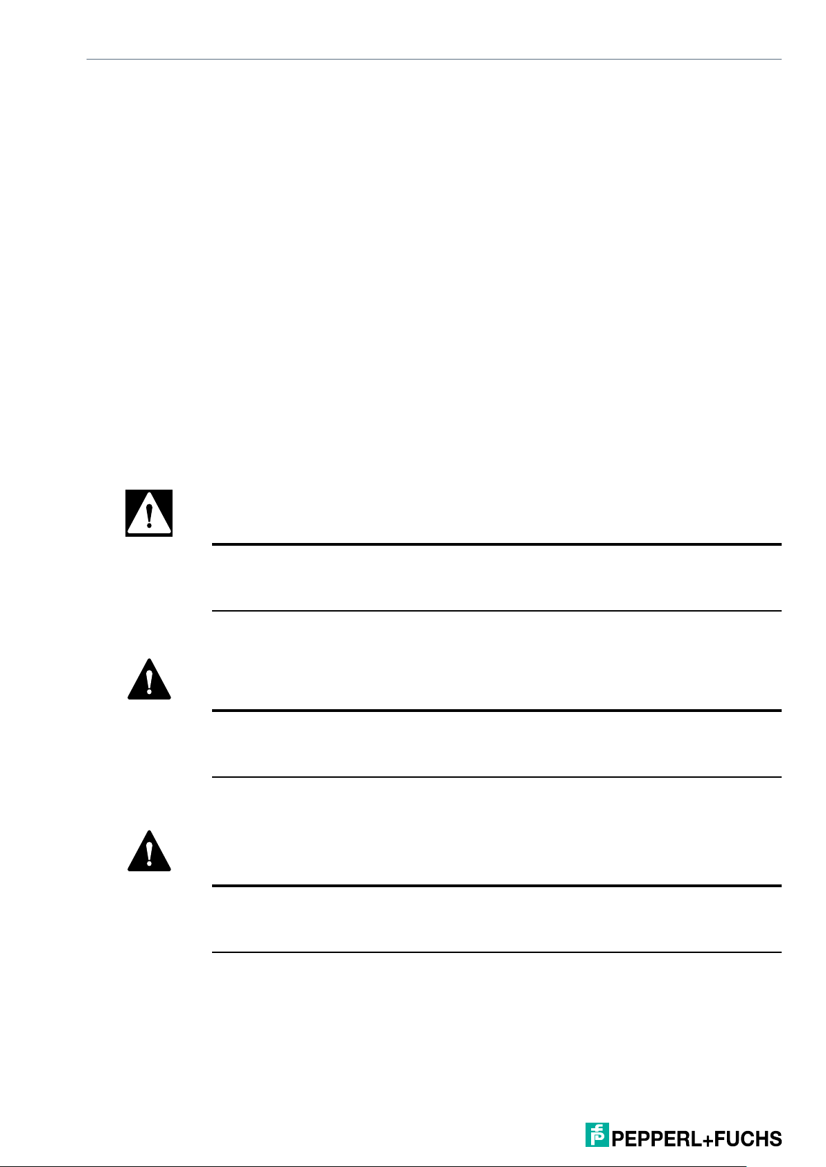
DANGER!
This symbol warns you of an immediate and present danger.
If you do not observe this warning message, there is a risk of personal injury and
even death.
WARNING!
This symbol warns you of a potential fault or hazard.
If you do not observe this warning message, there is a risk of personal injury or
severe property damage.
CAUTION!
This symbol warns you of a potential fault.
Failure to observe this warning message may result in the product or any systems
and plants connected to it malfunctioning or suering a complete failure.
2018-06
6
Page 7

ImporTanT noTes abouT The InsTruCTIon manual
Information messages
Note
This symbol draws your attention to important information.
Example
This symbol indicates an example.
Tip
This symbol indicates a tip is provided.
Handling instructions
This symbol highlights an action. You are prompted to perform an action or sequence
of actions.
1.2. Notes About The Manual
Please read the manual carefully before initial commissioning.
The instruction manual contains important information on the function and safety
regulations. If you do not observe this information, the intended use in explosion-hazardous areas cannot be guaranteed.
Observe the information given in this manual during commissioning and use of the
product.
2018-06
There is no responsibility for actuality. Pepperl+Fuchs GmbH reserves the right to
make changes to this document.
Prior to use, make sure that you have the latest version of the user manual. Check the
homepage www.pepperl-fuchs.com or contact your contact person at Pepperl+Fuchs
for clarication.
The gures in this manual are for illustration purposes only, and may dier from the
actual design in its appearance.
7
Page 8

ImporTanT noTes abouT The InsTruCTIon manual
DANGER!
Do not make any changes to the device that are not intended or been approved by
Pepperl+Fuchs.
Improper handling of the power module can void the type approval to operate in ex-
plosion-hazardous areas.
Non-compliance excludes warranty claims.
1.3. General Warning Messages
WARNING!
Only operate the devices when assembled.
Do not clean the device in explosion-hazardous areas. Do not wipe it dry.
Switch o the device immediately if you believe that the device can no longer be
operated safely after damaging eects or abnormalities in general (ingress of
water, uids, exposure to temperatures outside the specied range etc.).
Note general statutory regulations or directives on occupational safety, accident
prevention regulations and environmental protection laws, e.g., Ordinance on
Industrial Safety and Health (BetrSichV).
Do not open the device.
You may not make any changes to the device. You may not exchange or replace
any components. Explosion protection is no longer guaranteed for non-speci-
ed components.
Ensure safe handling during use through adequate stability and freedom of
movement.
Immediately remove the device from the explosion-hazardous area in the event
of damage to the housing.
IEC 60079-19 and IEC 60079-17 stipulate that you as the operator of electrical
plants in explosion-hazardous areas are obligated to appoint an electrician to
check that these plants are in perfect condition.
Do not insert any objects into the housing or other openings of the handheld
scanner. Openings on the device must not be obstructed, blocked, or covered.
Dispose of the device and the associated components correctly, as required by
law, by an approved company.
2018-06
8
Page 9

ImporTanT noTes abouT The InsTruCTIon manual
Note
Note the relevant deployment and operational regulations for electrical plants
(e.g., Directive 99/92/EC, Directive 2014/34/EU or the applicable national regulations, IEC 60 079-14, and the series DIN VDE 0100).
As the operator, perform maintenance and repair work for the device properly in
explosion-hazardous areas.
Maintenance
No ongoing maintenance is required when the mounting instructions, the ambient
conditions and proper operation are observed.
Inspection
The operator must appoint an electrician to check an electrically powered device in
explosion-hazardous areas, to ensure it is in correct condition (IEC 60079-19 and IEC
60079-17).
Repairs
Repairs may only be performed by the manufacturer or persons commissioned and
trained for this purpose.
WARNING!
The device is factory-sealed. It may be opened only by trained and qualied personnel at the factory.
Commissioning
Before you put the device into operation, check whether all the necessary components are available.
2018-06
9
Page 10

TeChnICal DaTa
TeChnICal DaTa
2. Technical Data
2.1. Explosion Protection
II 2G Ex eb q [ib IIC/IIB] IIC T4 Gb
II 2D Ex tb [ib] IIIC T135 °C Db
-25 °C ≤ Ta ≤ +60 °C
Test certicate
IBExU18ATEX1051
IECEx IBE 18.0010
Manufacturer
Pepperl+Fuchs GmbH
Lilienthalstraße 200
68307 Mannheim, Germany
info@de.pepperl-fuchs.com
2.2. Technical Data–Power Module for 1-D Handheld
Readers
PSU-IDM160-BD1D-J1-DC-S-N0
Description Power supply for the intrinsically safe supply of wired 1-D barcode readers
IDM160-D-1D-J1* and Bluetooth base station IDMx61-B-J1*
Electrical Data
Interfaces eld
side (Ex e)
Interfaces
scanner side
(Ex i)
RS232/RS422 USB RS232/RS422 USB
RS232 USB RS232 USB
PSU-IDM160-BD1D-J1-DC-U-N0
PSU-IDM160-BD1D-J1-AC-S-N0
PSU-IDM160-BD1D-J1-AC-U-N0
Operating voltage (nominal)
Voltage
range
Max. power
consumption
Frequency
range
10
24 VDC 230 VAC
18 VDC ... 30 VDC 90 VAC ... 253 VAC
7.1 W 16 W
- 50 Hz ... 60 Hz
2018-06
Page 11

TeChnICal DaTa
TeChnICal DaTa
PSU-IDM160-BD1D-J1-DC-S-N0
Power supply
cable
Data cable 0.2 mm² … 2.5
mm² (24 AWG …
14 AWG), 3-pin
Data cable max.
length
Ambient conditions
Operating
temperature
Storage
temperature
Relative
humidity
Housing
material
Mechanical Data
15 m 5 m 15 m 5 m
PSU-IDM160-BD1D-J1-DC-U-N0
0.2 mm² … 2.5 mm² (AWG24 … AWG14), 3-pin
0.2 mm² … 2.5
mm² (24 AWG …
14 AWG), 4-pin
-25 °C to 60 °C
-40 °C to 60 °C
95% non-condensing
PSU-IDM160-BD1D-J1-AC-S-N0
0.2 mm² … 2.5
mm² (24 AWG …
14 AWG), 3-pin
Aluminum
PSU-IDM160-BD1D-J1-AC-U-N0
0.2 mm² … 2.5
mm² (24 AWG …
14 AWG), 4-pin
Degree of protection
Dimensions (W
x H x D)
Weight approx. 3.1 kg
140 mm x 250 mm x 56 mm
IP64
2.3. Technical Data—Power Module for 2-D Handheld Readers
PSU-IDM260-D-2D-J1-DC-S-N0 PSU-IDM260-D-2D-J1-AC-S-N0
Description Power supply for the intrinsically safe supply of wired 2-D barcode readers
IDM260-D-2D-J1*
Electrical Data
Interfaces eld
side (Ex e)
Interfaces
scanner side
(Ex i)
RS232/RS422
RS232
Operating voltage (nominal)
Voltage
range
Max. power
consumption
2018-06
24 VDC 230 VAC
18 VDC ... 30 VDC 90 VAC ... 253 VAC
7.1 W 16 W
11
Page 12

TeChnICal DaTa
PSU-IDM260-D-2D-J1-DC-S-N0 PSU-IDM260-D-2D-J1-AC-S-N0
Frequency
range
Power supply
cable
Data cable 0.2 mm² … 2.5 mm² (24 AWG … 14 AWG), 3-pin
Data cable max.
length
Ambient conditions
Operating
temperature
Storage
temperature
Relative
humidity
Mechanical Data
Housing
material
Degree of protection
- 50 Hz ... 60 Hz
0.2 mm² … 2.5 mm² (AWG24 … AWG14), 3-pin
15 m
-25 °C to 60 °C
-40 °C to 60 °C
95% non-condensing
Aluminum
IP64
Dimensions (W
x H x D)
Weight approx. 3.1 kg
140 mm x 250 mm x 56 mm
2.4. Use
The power module is used for the intrinsically safe supply of devices.
The power module makes it possible to supply power in the explosion-hazardous
areas Zone 1 and Zone 21.
12
2018-06
Page 13

3. SyStem Structure
The power module is an accessory that supplies power to the wired Pepperl+Fuchs
handheld scanners IDM160-D-1D-J1*, IDM260-D-2D-J1* as well as to Bluetooth base station IDMx61-B-J1-BT-N0 and charging cradle IDMx61-C-BT-N0.
The corresponding system congurations of the power module with the respective
handheld scanners can be found in the manuals for the Pepperl+Fuchs IDM handheld
scanner series.
sysTem sTruCTure
2018-06
13
Page 14

CommIssIonIng
CommIssIonIng
4. Commissioning
4.1. Installation
Structure of the power module
1.
The power module is fastened to a stable base using the four mounting holes at the
1
corners of the base plate
1
Figure 1. Mounting points for installation
. The holes each have a diameter of 7 mm.
1
2. The connections for equipotential bonding (M5 x 10) are located on both the front
2
and back of the power module
2
.
2
14
Figure 2. Equipotential bonding connection
WARNING!
Equipotential bonding must be present for the entire duration
while the intrinsically safe circuits are being established!
2018 -0 6
Page 15

CommIssIonIng
CommIssIonIng
3.
1
Terminal compartment under covering xture
2
Cable gland M16 x 1.5 for consumers
3
Cable gland M16 x 1.5 for data transfer
4
Cable gland M20 x 1.5 for power supply
Figure 3. Terminal compartment and cable glands
WARNING!
1
2
3
4
Do not open the housing in the explosion-hazardous area!
Before the device is put into operation in explosion-hazardous areas, it must be
ensured that the housing is completely closed again and screwed on properly.
Note
Changes to the wiring may only be carried out by trained and qualied personnel.
4. The terminal assignment is located under the unscrewable opening on the front of
the power module.
1
Ex e terminal compartment to connect the power supply and the data line
2
Ex i terminal compartment to connect the consumers
1
2
Figure 4. Terminal compartment
2018 -0 6
15
Page 16

CommIssIonIng
4.2. Pin assignment in the terminal compartment
PSU-IDM160-BD-1D-J1-DC-S-N0 and PSUIDM260-D-2D-J1-DC-S-N0
X4
X1
Figure 5. Terminal blocks in the terminal compartment
Assignment for Ex e terminal compartment
Terminal no. Designation Description
X2
X3
X5
X6
X7
X8
X9
X10
X11
X12
X13
X1 +/- L + = 24 V DC
X2 -/N - = 0 V DC
X3 PE Protective earth
X4 GND RS232
X5 TxD RS232
X6 Shield RS232/RS422
X7 T+ RS422
X8 T- RS422
Assignment for Ex i terminal compartment
Terminal no. Designation
X9 RxD
X10 GND
X11 PE
X12 GND
X13 +UB
16
2018 -0 6
Page 17

CommIssIonIng
4.5. Pin assignment in the terminal compartment PSU-IDM160-BD-1D-J1-DC-U-N0
X4
X1
Figure 6. Terminal blocks in the terminal compartment
Assignment for Ex e terminal compartment
Terminal no. Designation Description
X1 +/- L + = 24 V DC
X2 -/N - = 0 V DC
X2
X3
X5
X6
X7
X8
X9
X10
X11
X12
X13
X3 PE Protective earth
X4 GND USB
X5 Shield USB
X6 n. c.
X7 D+ USB
X8 D- USB
Assignment for Ex i terminal compartment
Terminal no. Designation
X9 RxD
X10 GND
X11 PE
X12 GND
X13 +UB
2018 -0 6
17
Page 18

CommIssIonIng
4.6. Pin assignment in the terminal compartment
PSU-IDM160-BD-1D-J1-AC-S-N0 and PSUIDM260-D-2D-J1-DC-S-N0
X4
X1
Figure 7. Terminal blocks in the terminal compartment
Assignment for Ex e terminal compartment
Terminal no. Designation Description
X2
X3
X5
X6
X7
X8
X9
X10
X11
X12
X13
X1 +/- L L = 100 ... 250 V DC
X2 -/N N = Neutral conductor
X3 PE Protective earth
X4 GND RS232
X5 TxD RS232
X6 Shield RS232/RS422
X7 T+ RS422
X8 T- RS422
Assignment for Ex i terminal compartment
Terminal no. Designation
X9 RxD
X10 GND
X11 PE
X12 GND
X13 +UB
18
2018 -0 6
Page 19

CommIssIonIng
4.7. Pin assignment in the terminal compartment PSU-IDM160-BD-1D-J1-AC-U-N0
X4
X1
Figure 8. Terminal blocks in the terminal compartment
Assignment for Ex e terminal compartment
Terminal no. Designation Description
X1 +/- L L = 100 ... 250 V DC
X2 -/N N = Neutral conductor
X2
X3
X5
X6
X7
X8
X9
X10
X11
X12
X13
X3 PE Protective earth
X4 GND USB
X5 Shield USB
X6 n. c.
X7 D+ USB
X8 D- USB
Assignment for Ex i terminal compartment
Terminal no. Designation
X9 RxD
X10 GND
X11 PE
X12 GND
X13 +UB
2018 -0 6
19
Page 20

aCCesso rIes
aCCesso rIes
5. Accessories
Designation Description
Wired handheld barcode scanner
IDM160-D-1D-J1-SU-N-N0 Wired handheld scanner for 1-D codes
ATEX & IECEx Zone 1/21
IDM160-D-1D-J1-SU-P-N0 Wired handheld scanner for 1-D codes
ATEX & IECEx Zone 1/21
Supports PDF417 barcode
IDM260-D-2D-J1-S1-N-N0 Wired handheld scanner for 2-D codes
ATEX & IECEx Zone 1/21
Wireless handheld barcode scanner
IDM161-M-1D-J1-BT-N-N0 Bluetooth handheld scanner for 1-D codes
ATEX & IECEx Zone 1/21
IDM161-M-1D-J1-BT-P-N0 Bluetooth handheld scanner for 1-D codes
ATEX & IECEx Zone 1/21
Supports PDF417 barcode
IDM261-M-2D-J1-BT-N-N0 Bluetooth handheld scanner for 2-D codes
ATEX & IECEx Zone 1/21
Base station/charging cradle
IDMx61-B-J1-BT-N0 Bluetooth base station/charging cradle
ATEX & IECEx Zone 1/21
For IDMx61 Bluetooth handheld scanner
IDMx61-B-N0-BT-N0 Bluetooth base station/charging cradle
No explosion protection
For IDMx61 Bluetooth handheld scanner
IDMx61-C-N0-BT-N0 Charging cradle
No explosion protection
For IDMx61 Bluetooth handheld scanner
Power module
PSU-IDM160-BD-1D-J1-DCS-N0
PSU-IDM160-BD-1D-J1-DCU-N0
Power module for wired 1-D handheld scanner & Bluetooth base station
ATEX & IECEx Zone 1/21
RS232 connection, 24 VDC
For IDM160-D-1D-J1* and IDMx61-B-J1*
Power module for wired 1-D handheld scanner & Bluetooth base station
ATEX & IECEx Zone 1/21
USB connection, 24 VDC
For IDM160-D-1D-J1* and IDMx61-B-J1*
PSU-IDM160-BD-1D-J1-ACS-N0
PSU-IDM160-BD-1D-J1-ACU-N0
20
Power module for wired 1-D handheld scanner & Bluetooth base station
ATEX & IECEx Zone 1/21
RS232 connection, 230 VAC
For IDM160-D-1D-J1* and IDMx61-B-J1*
Power module for wired 1-D handheld scanner & Bluetooth base station
ATEX & IECEx Zone 1/21
USB connection, 230 VAC
For IDM160-D-1D-J1* and IDMx61-B-J1*
2018 -0 6
Page 21

Designation Description
aCCesso rIes
PSU-IDM260-D-2D-J1-DCS-N0
Power module for wired 2-D handheld scanner
ATEX & IECEx Zone 1/21
RS232 connection, 24 VDC
For IDM260-D-2D-J1*
PSU-IDM260-D-2D-J1-ACS-N0
Power module for wired 2-D handheld scanner
ATEX & IECEx Zone 1/21
RS232 connection, 230 VAC
For IDM260-D-2D-J1*
PSU-IDMx61-BC-N0-N0 Power supply for non-explosion-hazardous base station & charger
No explosion protection
For IDMx61-B-N0-BT-N0 and IDMx61-C-N0-BT-N0
Cordset for wired handheld scanner/power module
CBL-IDMx60-D-J1-S-S18-N0 RS232 connection cable wired 1-D/2-D handheld scanner
ATEX & IECEx Zone 1/21
1.8 m length, smooth
For IDMx60-D-*
CBL-IDMx60-D-J1-S-C38-N0 RS232 connection cable wired 1-D/2-D handheld scanner
ATEX & IECEx Zone 1/21
3.8 m length, spiral
For IDMx60-D-*
CBL-IDM160-D-J1-U-S18-N0 RS232 connection cable wired 1-D handheld scanner
ATEX & IECEx Zone 1/21
1.8 m length, smooth
For IDM160-D-*
CBL-IDM160-D-J1-U-C38-N0 RS232 connection cable wired 1-D handheld scanner
ATEX & IECEx Zone 1/21
3.8 m length, spiral
For IDM160-D-*
Cordset for base station/power module
CBL-IDMx61-B-N0-S-S18-N0 RS232 connection cable base station
No explosion protection
1.8 m length, smooth
For IDMx61-B-N0*
CBL-IDMx61-B-N0-S-C38-N0 RS232 connection cable base station
No explosion protection
3.8 m length, spiral
For IDMx61-B-N0*
CBL-IDMx61-B-N0-U-S18-N0 USB connection cable base station
No explosion protection
1.8 m length, smooth
For IDMx61-B-N0*
CBL-IDMx61-B-N0-U-C38-N0 USB connection cable base station
No explosion protection
3.8 m length, spiral
For IDMx61-B-N0*
CBL-IDMx61-B-J1-S-S18-N0 RS232 connection cable base station
ATEX & IECEx Zone 1/21
1.8 m length, smooth
For IDMx61-B-J1*
2018 -0 6
21
Page 22

aCCesso rIes
Designation Description
CBL-IDMx61-B-J1-S-C38-N0 RS232 connection cable base station
ATEX & IECEx Zone 1/21
3.8 m length, spiral
For IDMx61-B-J1*
CBL-IDMx61-B-J1-U-S18-N0 USB connection cable base station
ATEX & IECEx Zone 1/21
1.8 m length, smooth
For IDMx61-B-J1*
CBL-IDMx61-B-J1-U-C38-N0 USB connection cable base station
ATEX & IECEx Zone 1/21
3.8 m length, spiral
For IDMx61-B-J1*
Accessories
SCANNER-HOLDER-ID-
Tripod holder for IDMx6x handheld scanner
Mx6x-TRIPOD
SCANNER-HOLDER-ID-
Desktop holder for IDMx6x handheld scanner
Mx6x-DESKTOP
SCANNER-HOLDER-U1AG1-N0
SCANNER-HOLDER-U1XX00-N0
HOLDER-BRACKET-XX00IDMx61-B-N0
Stainless steel holder for IDMx6x handheld scanner, compatible
with AG1 surrounding enclosure
Stainless steel holder for IDMx6x handheld scanner, compatible
with AG-XX00 surrounding enclosure
Stainless steel bracket for mounting the base station IDMx61-BJ1-BT-N0 to the AG-XX00 surrounding enclosure
BAT-IDMx61-M Replacement battery li-ion
For IDM161-M* and IDM261-M*
S-RN2/DB9-5-N0 RS232 cable with SUB-D9 plug (female) and open cable ends with
wire end ferrules, 5 m length
S-RN2/DB9-20-N0 RS232 cable with SUB-D9 plug (female) and open cable ends with
wire end ferrules, 20 m length
S-UN2/USB-5-N0 USB cable with USB Type A plug (male) and open cable ends with
wire end ferrules, 5 m length
DATL-IDM-DB-S-XX00-N0 Cordset for wired 1-D handheld scanner IDM160-D-1D-J1-S*,
2-D handheld scanner IDM260-D-2D-J1-S* and the Bluetooth
base station IDMx61-B-J1-BT-N0 to VisuNet GXP in the AG-XX00
housing
Note: supports RS232 scanner/base station only!
DATL-A3 -1.5-1 Supply line for 90 – 240 VAC supply
3 x 1.5 mm², diameter 8.1 mm
Assembly 6 x 1.5 mm² wire end ferrules
22
2018 -0 6
Page 23

Pepperl+Fuchs Quality
Download our latest policy here:
www.pepperl-fuchs.com/quality
www.pepperl-fuchs.com
www.pepperl-fuchs.com
www.pepperl-fuchs.com
Subject to modifications
Subject to modifications
Subject to modications · © Pepperl+Fuchs
Printed in Germany
Printed in Germany
Printed in Germany · 2018-06 · DOCT-6119
© Pepperl+Fuchs
© Pepperl+Fuchs
·
·
Part. No. 000000 00/00 00
Part. No. 000000 00/00 00
·
·
 Loading...