

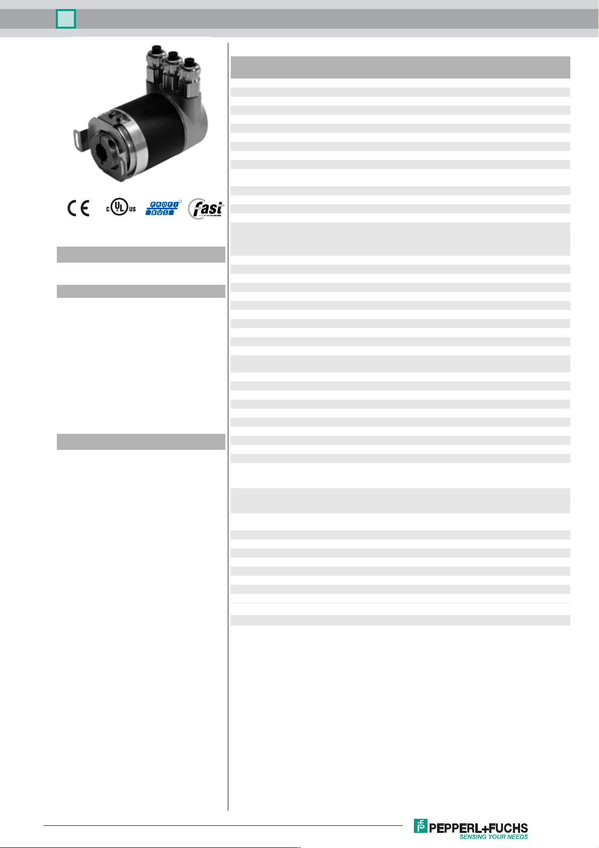
Multiturn absolute encoder PSM58
Technical data
General specifications
Detection type photoelectric sampling
Device type Multiturn absolute encoder
Functional safety related parameters
R
Model Number
PSM58
Features
• Industrial standard
housing Ø58 mm
• PROFIBUS interface
• 30 Bit multiturn
• Speed transfer
• Extended scaling functions
• Programmable limit switches
• Commissioning mode
• Recessed hollow shaft
Description
This series of PROFIBUS rotary encoders is based
on the modern fast technology of singleturn sampling and the mechanical gear box of the multiturn
unit. The absolute encoder corresponds to the
PROFIBUS profile for encoders, order no. 3.062.
Operation is supported based on Class 1 and Class
2.
For operation based on Class 1, position data and
diagnostic data bytes 1 ... 16 are available. In addi-
tion, the direction of the code can be selected as
either cw ascending (clockwise rotation, code
course ascending) or cw descending (clockwise rotation, code course descending).
If the rotary encoder is operated according to Class
2, additional functions to those from Class 1 are
available. These include scaling of the resolution
per revolution and the overall resolution, as well as
the preset function. In addition, expanded diagnostic reporting is supported.
Besides, the rotary encoder offers extended functionalities such as speed transfer, extended scaling
functions, programmable limit switches and a commissioning mode.
The removable connecting hood contains a slide
switch for setting the terminating resistor and the
rotary switches for setting the address. Assign a
fixed address and bus termination to the encoder
with this switches.
The absolute encoder is mounted directly onto the
application shaft, without any coupling. Rotation of
the absolute encoder is prevented by a torque rest.
MTTF
d
Mission Time (TM) 20 a
L
1.9 E+11 at 6000 rpm and 20/40 N axial/radial shaft load
10h
Diagnostic Coverage (DC) 0 %
Electrical specifications
Operating voltage U
No-load supply current I
Power consumption P
Time delay before availability t
Linearity ± 2 LSB at 16 Bit, ± 1 LSB at 13 Bit, ± 0,5 LSB at 12 Bit
Output code binary code
Code course (counting direction) programmable,
Interface
Interface type PROFIBUS
Resoluti
on
Single turn up to 16 Bit
Multit
urn 14
Overall resolution up to 30 Bit
Transfer rate 0.0096 ... 12 MBit/s
Standard conformity PNO profile 3.062, RS-485
Connection
Terminal compartment in removable housing cover
Standard conformity
Degree of protection DIN EN 60529, IP65
Climatic testing DIN EN 60068-2-30 , no moisture condensation
Emitted interference EN 61000-6-4:2007
Noise immunity EN 61000-6-2:2005
Shock resistance DIN EN 60068-2-27, 100 g, 6 ms
Vibration resistance DIN EN 60068-2-6, 20 g, 10 ... 2000 Hz
Ambient conditions
Operating temperature -40 ... 85 °C (-40 ... 185 °F)
Storage temperature -40 ... 85 °C (-40 ... 185 °F)
Mechanical specifications
Material
ation 1 housing: powder coated aluminum
Combin
Combination 2 (Inox) housing: stainless steel
Mass approx. 600 g (combination 1)
Rotational speed max. 12000 min
Moment of inertia 30 gcm
Starting torque ≤ 3 Ncm (version without shaft seal)
Tightening torque, fastening screws max. 1.8 Nm
Shaft load
le offset ± 0.9 °
Ang
Axial offset static: ± 0.3 mm, dynamic: ± 0.1 mm
Radial offset static: ± 0.5 mm, dynamic: ± 0.2 mm
Approvals and certificates
UL approval cULus Listed, General Purpose, Class 2 Power Source
B
0
0
v
70 a
10 ... 30 V DC
max. 230 mA at 10 V DC
max. 100 mA at 24 V DC
max. 2.5 W
< 1000 ms
cw ascending (clockwise rotation, code course ascending)
cw descending (clockwise rotation, code course
descending)
Bit
IP66 (with shaft seal)
flange: aluminum
shaft: stainless steel
flange: stainless steel
shaft: stainless steel
approx. 1200 g (combination 2)
-1
2
Release date: 2016-02-16 16:50 Date of issue: 2016-02-16 t49155_eng.xml
Refer to “General Notes Relating to Pepperl+Fuchs Product Information”.
1
Multiturn absolute encoder PSM58
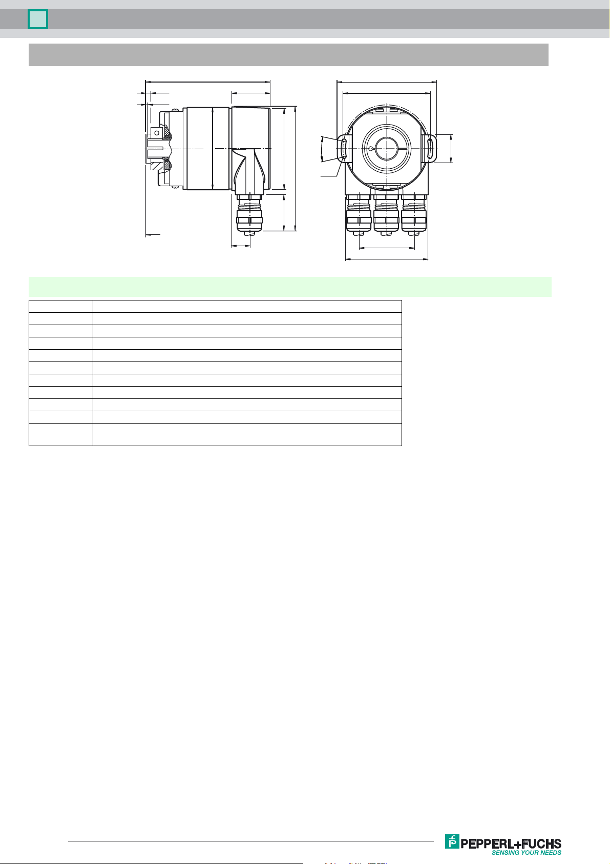
Dimensions
L
2.5
max. insertion
depth = 30
min. insertion
Lay-on edge
torque rest
depth = 15
5
ø 59
12.7
27.5
ø 58
25
L: Singleturn = 87
Multiturn = 98
Electrical connection
Terminal Explanation
⊥ Ground connection for power supply
B (left) Data line B (pair 1), Bus In
A (left) Data line A (pair 1), Bus In
(-) 0 V
(+) 10 V ... 30 V
B (right) Data line B (pair 2), Bus Out
A (right) Data line A (pair 2), Bus Out
(-) 0 V
(+) 10 V ... 30 V
The supply lines only have to be connected once (regardless to which terminal).
The outgoing bus is being uncoupled while the terminal resistor is on.
The arrangement of the terminals is shown in the section operating elements.
72
ø 63
20°
88
R 1.6
40
60
20
Release date: 2016-02-16 16:50 Date of issue: 2016-02-16 t49155_eng.xml
Refer to “General Notes Relating to Pepperl+Fuchs Product Information”.
2

Multiturn absolute encoder PSM58
x10
x1
Indicating and operating elements
Termination resistor
Supply voltage
R
T
ON
RS 485 interface
Supply voltage
Error indicator
LED red
Bus Out
Data line A
Data line B
Bus IN
+-+
A
BAB-
0
0
9 1
9 1
2
2
8
8
3
3
7
7
4
4
6
6
5
5
x1
x10
Data line A
Data line B
2
Addressing
Adjusting the participant address
The participant address can be adjusted with the rotary switches. The address can be defined between 1 and 99, and may
only be assigned once.
Adjusting the termination resistor
The terminating resistor RT (220 Ω) can be connected to the circuit by means of the switch:
LED-indicators
LED red LED green Meaning
off off No voltage supply
Encoder ready, no configuration data received.
on on
on
flashing
flashing on Encoder ready, no communication with master (i.e. wrong address setting)
on off Data timeout (> 40 s). (i.e. data lines interrupted)
off on Normal operation, Data Exchange Mode
off flashing Installation Mode in Data Exchange Mode.
possible reasons:
- wrong address adjusted
- wrong bus wiring
Parameterising or configuration error. Encoder receives data of incorrect length or inconsistant data.
possible reason:
- adjusted encoder resolut
ion exceeds
participant X last participant
R
T
ON
8
7
ON
Status indicator
LED green
0
9 1
2
3
4
6
5
x10
R
T
9 1
8
7
6
x1
0
2
3
4
5
Release date: 2016-02-16 16:50 Date of issue: 2016-02-16 t49155_eng.xml
Refer to “General Notes Relating to Pepperl+Fuchs Product Information”.
3

Multiturn absolute encoder PSM58
Principle of data transmission
GSD file
Software
Definition of device class
enter parameter
Data base
Control
Parameter ("DDLM_Set_Prm")
onetime at start up
cyclical data interchange
(e. g. position value)
Parameter table encoder classes P+F 2.1 and P+F 2.2
Octet number (Byte) Parameter Bit number
1...8 PROFIBUS standard parameters
9 Direction of rotation 0
Class 2 functionality 1
Commissioning Diagnostics 2
Scaling function 3
Reserved 4
Reserved 5
Activate manufacturer specific parameters (Octet 26) 6
Reserved 7
10 ... 13 Desired measuring steps (reference: Octet 26, Bit 0 and 1)
14 ... 17 Overall resolution
18 ... 25 Reserved
26 Reference for desired measuring steps 0
1
Activate commissioning mode 2
Reduced diagnosis 3
Reserved 4
Activate lower software limit switch 5
Activate upper software limit switch 6
Activation of the parameters from Octet 27 7
27 ... 30 Lower limit switch
31 ... 34 Upper limit switch
35 ... 38 Physical measuring steps
39 Reserved 0
Rotary encoder type (singleturn or multiturn) 1
Reserved 2
Reserved 3
Selection of the unit for speed transfer 4
5
Reserved 6
Reserved 7
Encoder
Release date: 2016-02-16 16:50 Date of issue: 2016-02-16 t49155_eng.xml
Refer to “General Notes Relating to Pepperl+Fuchs Product Information”.
4

Multiturn absolute encoder PSM58
Order code
PSM58 – R0BN–
Number of bits singleturn
13 8192 (standard)
16 65536
Number of bits multiturn
12 4096 (standard)
14 16384
Option 2
N Not expanded
Output code
B Binary
Option 1
0 No option
Exit position
R Radial
Connection type
AG Removable housing cover with terminal compartment
AZ Removable housing cover with M12 connectors
Shaft dimension/flange version
F1A Recessed hollow shaft Ø10 mm x 30 mm
F2A Recessed hollow shaft Ø12 mm x 30 mm
F3A Recessed hollow shaft Ø15 mm x 30 mm
Housing material
N Aluminium, powder coated
I Inox
W Aluminium, powder coated with shaft seal
Principle of operation
M Multiturn
Shaft version
S Recessed hollow shaft
Data format
P PROFIBUS
Release date: 2016-02-16 16:50 Date of issue: 2016-02-16 t49155_eng.xml
Refer to “General Notes Relating to Pepperl+Fuchs Product Information”.
5
 Loading...