

Page 1
Release date 2020-08-06 DOCT-6918 Refer to „General Notes Relating to Pepperl+Fuchs Product Information“
Validity
Specifi c processes and instructions in this instruction manual require special
provisions to guarantee the safety of the operating personnel.
Target Group, Personnel
Responsibility for planning, assembly, commissioning, operation,
maintenance, and dismounting lies with the plant operator.
The personnel must be appropriately trained and qualifi ed in order to carry
out mounting, installation, commissioning, operation, maintenance, and
dismounting of the device. The trained and qualifi ed personnel must have
read and understood the instruction manual.
Reference to Further Documentation
Observe laws, standards, and directives applicable to the intended use
and the operating location. Observe Directive 1999/92/EC in relation to
hazardous areas.
The corresponding datasheets, manuals, declarations of conformity, ECtype-examination certifi cates, certifi cates, and control drawings if applicable
(see datasheet) are an integral part of this document. You can fi nd this
information under www.pepperl-fuchs.com.
Intended Use
PS*-7* plugs are intended for use with PS*-4* sockets in the hazardous
locations outlined in the corresponding certifi cates to create a connection
point between two devices.
Mounting and Installation
Observe the installation instructions according to IEC/EN 60079-14.
1. Installation of sockets PS*-4*
Loosen the cover screws and detach the cover from the wall socket.
Open the cable gland and push the cable through it.
Strip the cable outer sheath to a suitable length.
Strip the individual cores to a suitable length and connect them to the relevant
terminals.
Connect the ground conductor to the grounding terminal.
Make sure all cores are terminated using the correct torque, including the
ground conductor.
Secure the cable tightly in the gland by screwing the cap to the correct torque.
Carefully place the cover back onto the wall socket and tighten the fi xing
screws to the correct torque.
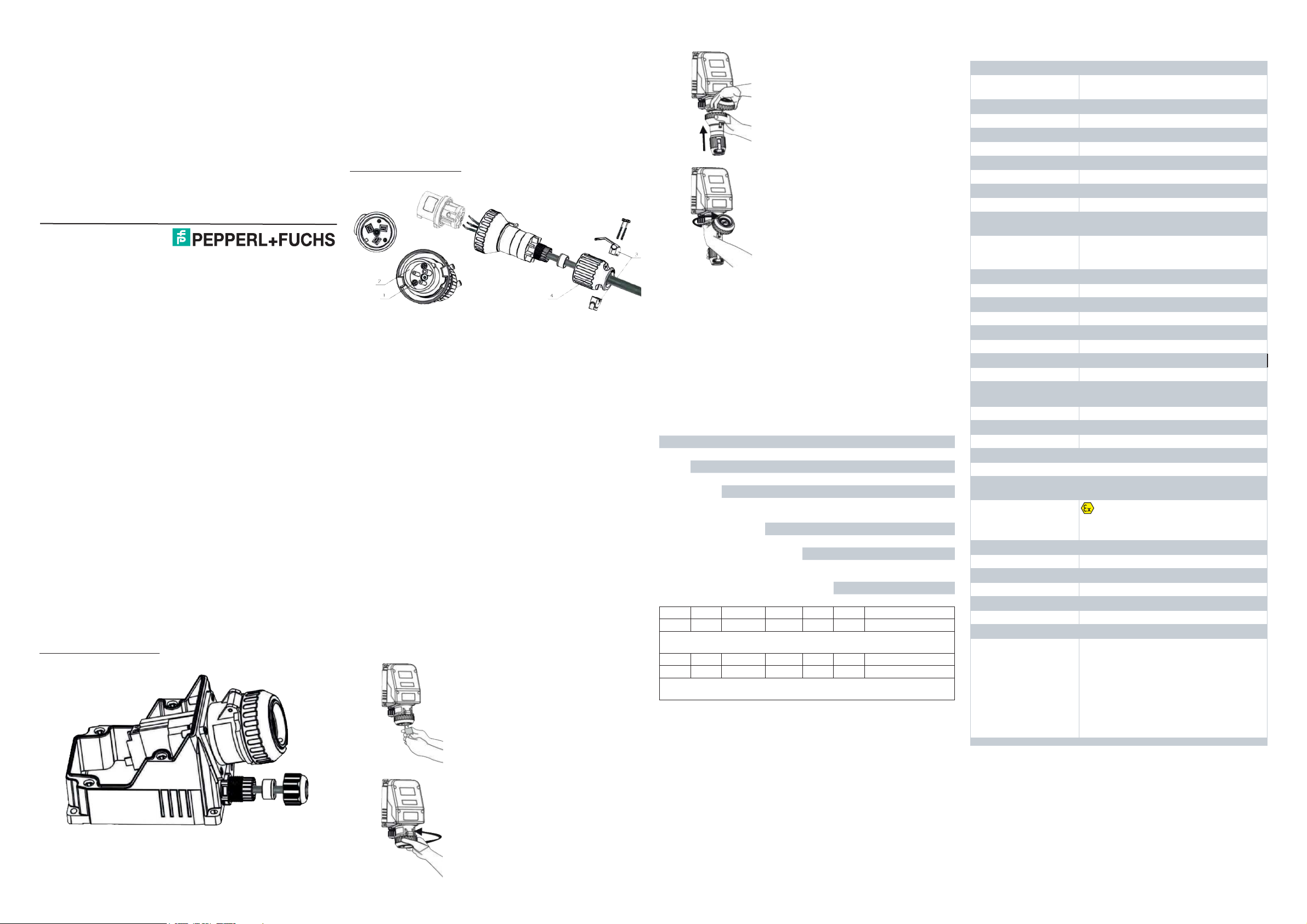
2. Installation of plugs PS*-7*
Unscrew the screws (1) near the pins inside the front part (2) until you can
detach the front part from the housing.
Unscrew the two screws which hold the strain relief (3) and loosen the
strain relief.Unscrew the end part (4) completely until it is detached from the
enclosure.
Push the end part (4) over the cable.
Push the cable through the gasket of the housing until it appears at the front
part.
Strip the insulation of the individual cores of the cable.
Connect the cores to the individual terminals of the front part (2). Connect
each conductor to its respective terminal. Connect the grounding conductor
to the grounding terminal.
Reconnect the front part (2) to the housing by fi xing the two screws (2).
Screw the end part (4) back onto the housing.
Attach the strain relief (3) by means of the two screws.
Operation, Maintenance, Repair
Observe IEC/EN 60079-17 for maintenance and inspection.
The device must be disconnected from the power supply prior to installation
and maintenance. The power supply may be activated only after all the
circuits required for operation have been fully assembled and connected.
Do not modify or manipulate the device.
Modifi cations are permitted only if approved in this instruction manual.
The PS* sockets may only be used with associated PS* plugs.
Use the plugs and sockets only when they are clean and not damaged.
If a padlock was used to protect
the socket against misuse, then the
padlock has to be detached.
Open the bayonet catch by turning it
counter-clockwise by approx. 120°.
Technical Specifi cations
General
Type and variants
PS*-4*, see type code table
PS*-7*, see type code table
Electrical specifications
Operating voltage
see table
Operating current see table
Terminal capacity see table
Supply frequency 50/60 Hz
Function plug or socket
Usage category see table
Number of poles see table
Color coding according
to IEC 60309
see table
Protective contact
position according to
IEC 60309
see table
Mechanical specifications
Cable type non-armored cables
Cover fixing see table
Degree of protection IP66
Number of cable entries see table, 1x cable gland, 1x stopping plug
Mass see table
Dimensions see table
Material
Housing PS*-4*
carbon loaded, antistatic glass fiber reinforced
polyester (GRP)
Housing PS*-7* polyamide (PA)
Finish inherent color black
Ambient conditions
Ambient temperature -40 ... 55 °C (-40 ... 131 °F)
Data for application in connection with hazardous areas
EU-type examination
certificate
SIRA 11 ATEX 1044
Marking
II 2 GD
Ex de IIC T6 Gb
Ex t IIIC T80 °C Db
International approvals
IECEx approval IECEx SIR 11.0026
Conformity
Degree of protection EN 60529
Usage category IEC / EN 60947
CE marking 102
Plug connection IEC 60309
Standards
EN60079-0:2012
EN60079-1:2014
EN60079-7:2015
EN60079-31:2014
and/or
IEC60079-0:2011
IEC60079 -1:2014
IEC60079-7:2015
IEC60079-31:2013
Sockets PS*-4*
Plugs PS*-7*
Delivery, Transport, Disposal
Disposing of device and packaging must be in compliance with the applicable
laws and guidelines of the respective country.
Type Code / Model Number
Device type
PS Plugs and Sockets Ex de
| Operating current
| nn max. A, see data table
| | Variant
| | -4 socket
| | -7 plug
| | | Number of poles
| | | 3 ... 5 see data table
| | | | Pin configuration
| | | | nn
pins and protective contact
positioning, see data table
| | | | | Auxiliary contacts
| | | | | 00 none
PS 125 -4 5 06 00 Example
Example: Socket Ex de max. 125 A, 380 ... 415 V, 5-pole red, protective
contact position 6 h
PS 16 -7 3 04 00 Example
Example: Plug Ex de max. 16 A, 110 ... 113 V, 3-pole yellow, protective
contact position 4 h
Push the plug into the socket so
that the nose of the plug fi ts into the
respective opening in the socket
fl ange.
Activate the socket by turning the
plug 30° clockwise.
Secure the IP protection of the plug
and socket assembly by closing the
bayonet catch of the plug by turning
it 120° clockwise.
Brief Instructions
Pepperl-Fuchs GmbH
Lilienthalstrasse 200
69307 Mannheim, Germany
Tel. +49 621 776-0
Fax +49 621 776-1000
Document No.: DOCT-6918
Edition: 08/2020
Copyright Pepperl+Fuchs
www.pepperl-fuchs.com
ENG
Page 2
Release date 2020-08-06 DOCT-6918 Refer to „General Notes Relating to Pepperl+Fuchs Product Information“
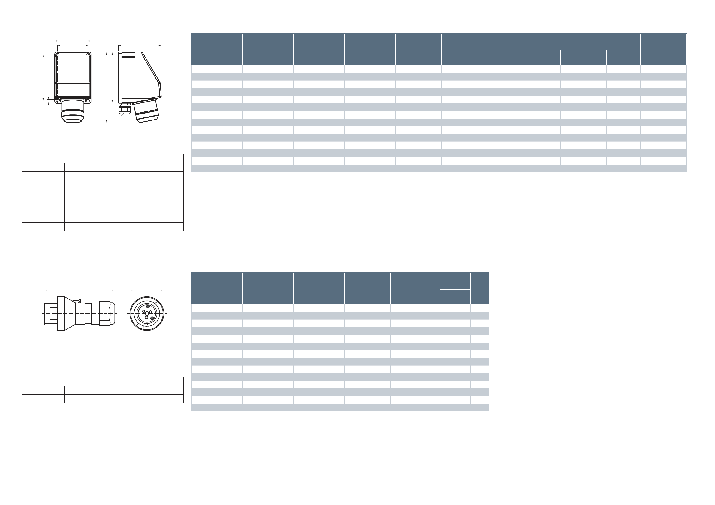
Dimensions Sockets PS*-4*
H
B
C
A
K
SW1
J
G
Dimensions Plugs PS*-7*
L D
Dimension values see data table.
Image and drawing are generic for this device type and may deviate from the
specifi c variant.
Legend
L
Total length
D
Diameter
Dimension values see data table.
Image and drawing are generic for this device type and may deviate from the
specifi c variant.
Legend
A
External dimension
B
External dimension
C
External dimension, depth
G
Mounting holes distance
H
Mounting holes distance
J
Mounting holes diameter
K
Maximum external dimension
SW1
Cable entry
Variant-Specifi c Data Sockets PS*-4*
Type
Operating
voltage
[V]
Operating
current
max. [A]
Main
terminals
capacity
[mm2]
Main
terminals
torque
[Nm]
Usage category
Number
of poles
Color
coding
according
to IEC
60309
Protective
contact
position
according
to IEC
60309
Number
of cable
entries
Clamping
range
[mm]
External dimensions
[mm]
Mounting
[mm]
Mass
approx.
[kg]
Cover screws
A B C K G H J Mx qty.
Torque
[Nm]
PS16-430400 100 ... 130 16 2.5 2.5 AC3: 690 V AC - 16 A 3 yellow 4 h 2x M25 8 ... 17 156 103 122 223 142 86 6 1.2 M4 4 2.5
PS16-430600 200 ... 250 16 2.5 2.5 AC3: 690 V AC - 16 A 3 blue 6 h 2x M25 8 ... 17 156 103 122 223 142 86 6 1.2 M4 4 2.5
PS16-440600 380 ... 415 16 2.5 2.5 AC3: 690 V AC - 16 A 4 red 6 h 2x M25 8 ... 17 176 123 147 241 163 106 6 1.2 M4 4 2.5
PS16-440700 480 ... 500 16 2.5 2.5 AC3: 690 V AC - 16 A 4 black 7 h 2x M25 8 ... 17 176 123 147 241 163 106 6 1.2 M4 4 2.5
PS16-450600 380 ... 415 16 2.5 2.5 AC3: 690 V AC - 16 A 5 red 6 h 2x M25 8 ... 17 176 123 147 241 163 106 6 1.2 M4 4 2.5
PS32-440600 380 ... 415 32 6 2.5 AC3: 690 V AC - 32 A 4 red 6 h 2x M32 12 ... 21 211 133 162 294 198 118 6 1.8 M4 4 2.5
PS32-440700 480 ... 500 32 6 2.5 AC3: 690 V AC - 32 A 4 black 7 h 2x M32 12 ... 21 211 133 162 294 198 118 6 1.8 M4 4 2.5
PS32-450600 380 ... 415 32 6 2.5 AC3: 690 V AC - 32 A 5 red 6 h 2x M32 12 ... 21 211 133 162 294 198 118 6 1.8 M4 4 2.5
PS63-440600 380 ... 415 63 16 3 AC3: 690 V AC - 63 A 4 red 6 h 2x M50 22 ... 35 371 201 248 472 352 181 9 8.25 M6 4 3
PS63-440700 480 ... 500 63 16 3 AC3: 690 V AC - 63 A 4 black 7 h 2x M50 22 ... 35 371 201 248 472 352 181 9 8.25 M6 4 3
PS63-450600 380 ... 415 63 16 3 AC3: 690 V AC - 63 A 5 red 6 h 2x M50 22 ... 35 371 201 248 472 352 181 9 8.83 M6 4 3
PS125-440600 380 ... 415 125 50 3 AC3: 690 V AC - 125 A 4 red 6 h 2x M63 27 ... 48 431 249 274 538 411 228 9 13 M6 4 3
PS125-440700 480 ... 500 125 50 3 AC3: 690 V AC - 125 A 4 black 7 h 2x M63 27 ... 48 431 249 274 538 411 228 9 8.25 M6 4 3
PS125-450600 380 ... 415 125 50 3 AC3: 690 V AC - 125 A 5 red 6 h 2x M63 27 ... 48 431 249 274 538 411 228 9 14 M6 4 3
Variant-Specifi c Data Plugs PS*-7*
Type
Operating
voltage
[V]
Operating
current
max. [A]
Main
terminals
capacity
[mm2]
Main
terminals
torque
[Nm]
Number
of poles
Color
coding
according
to IEC
60309
Protective
contact
position
according
to IEC
60309
Clamping
range
[mm]
External
dimensions
[mm]
Mass
approx.
[kg]
D L
PS16-730400 110 ... 130 16 2.5 0.8 3 yellow 4 h 6.5 ... 18.5 73 163 0.35
PS16-730600 200 ... 250 16 2.5 0.8 3 blue 6 h 6.5 ... 18.5 73 163 0.35
PS16-740600 380 ... 415 16 2.5 0.8 4 red 6 h 6.5 ... 20 77 187 0.35
PS16-740700 480 ... 500 16 2.5 0.8 4 black 7 h 6.5 ... 20 77 187 0.35
PS16-750600 380 ... 415 16 2.5 0.8 5 red 6 h 6.5 ... 20 84 187 0.35
PS32-740600 380 ... 415 32 6 0.8 4 red 6 h 10 ... 28 101 232 0.7
PS32-740700 480 ... 500 32 6 0.8 4 black 7 h 10 ... 28 101 232 0.7
PS32-750600 380 ... 415 32 6 0.8 5 red 6 h 10 ... 28 101 232 0.7
PS63-740600 380 ... 415 63 16 0.8 4 red 6 h 15 ... 35 111 262 0.81
PS63-740700 480 ... 500 63 16 0.8 4 black 7 h 15 ... 35 111 262 0.81
PS63-750600 380 ... 415 63 16 0.8 5 red 6 h 15 ... 35 111 262 0.86
PS125-740600 380 ... 415 125 50 0.8 4 red 6 h 20 ... 57 121 298 1.25
PS125-740700 480 ... 500 125 50 0.8 4 black 7 h 20 ... 57 121 298 1.25
PS125-750600 380 ... 415 125 50 0.8 5 red 6 h 20 ... 57 121 298 1.3
 Loading...