

Page 1

FACTORY AUTOMATION
MANUAL
WCS-PNG210
WCS PROFINET IO
Interface Module
Page 2

WCS-PNG210
With regard to the supply of products, the current issue of the following document is ap-
plicable: The General Terms of Delivery for Products and Services of the Electrical Indus-
try, published by the Central Association of the Electrical Industry (Zentralverband
Elektrotechnik und Elektroindustrie (ZVEI) e.V.) in its most recent version as well as the
supplementary clause: "Expanded reservation of proprietorship"
Page 3

WCS-PNG210
1 Introduction................................................................................. 4
1.1 Content of this Document ................................................................... 4
1.2 Target Group, Personnel...................................................................... 4
1.3 Symbols Used ...................................................................................... 4
2 Product Description ................................................................... 6
2.1 Use and Application............................................................................. 6
2.2 Dimensions........................................................................................... 6
2.3 Design of the Device............................................................................ 7
3 Installation................................................................................. 10
3.1 Mounting ............................................................................................. 10
3.2 Electrical Connection ........................................................................ 11
3.3 Dismounting ....................................................................................... 13
4 Commissioning......................................................................... 15
4.1 Introduction ........................................................................................ 15
4.2 Connecting WCS Readers................................................................. 16
4.3 Connecting the WCS-PNG210 to the Network ................................ 16
4.4 Integrating WCS-PNG210 into the Network..................................... 17
4.5 Data Format for Modules ................................................................... 20
5 Appendix ................................................................................... 22
5.1 Cable Routing in the RS-485 Bus ..................................................... 22
5.2 Data Cables and Accessories ........................................................... 25
3
Page 4

WCS-PNG210
Introduction
1 Introduction
1.1 Content of this Document
This document contains information required to use the product in the relevant phases of the
product life cycle. This may include information on the following:
■
Product identification
■
Delivery, transport, and storage
■
Mounting and installation
■
Commissioning and operation
■
Maintenance and repair
■
Troubleshooting
■
Dism ounting
■
Disposal
Note!
Visit www.pepperl-fuchs.com to access further documentation for full information about the
product.
The documentation comprises the following parts:
■
This document
■
Datasheet
In addition, the documentation may comprise the following parts, if applicable:
■
EU-type examination certificate
■
EU declaration of conformity
■
Attestation of conformity
■
Certificates
■
Control drawings
■
Instruction manual
■
Other documents
1.2 Target Group, Personnel
Responsibility for planning, assembly, commissioning, operation, maintenance, and
dismounting lies with the plant operator.
Only appropriately trained and qualified personnel may carry out mounting, installation,
commissioning, operation, maintenance, and dismounting of the product. The personnel must
have read and understood the instruction manual and the further documentation.
Prior to using the product make yourself familiar with it. Read the document carefully.
2018-03
4
Page 5
WCS-PNG210
Introduction
1.3 Symbols Used
This document contains symbols for the identification of warning messages and of informative
messages.
Warning Messages
You will find warning messages, whenever dangers may arise from your actions. It is mandatory
that you obser ve these warning messages for your personal safety and in order to avoid
property damage.
Depending on the risk level, the warning messages are displayed in descending order as
follows:
Danger!
This symbol indicates an imminent danger.
Non-observance will result in personal injury or death.
Warning!
This symbol indicates a possible fault or danger.
Non-observance may cause personal injury or serious property damage.
Caution!
This symbol indicates a possible fault.
Non-observance could interrupt the device and any connected systems and plants, or result in
their complete failure.
Informative Symbols
Note!
This symbol brings important information to your attention.
Action
This symbol indicates a paragraph with instructions. You are prom pted to perform an action or
a sequence of actions.
2018-03
5
Page 6
WCS-PNG210
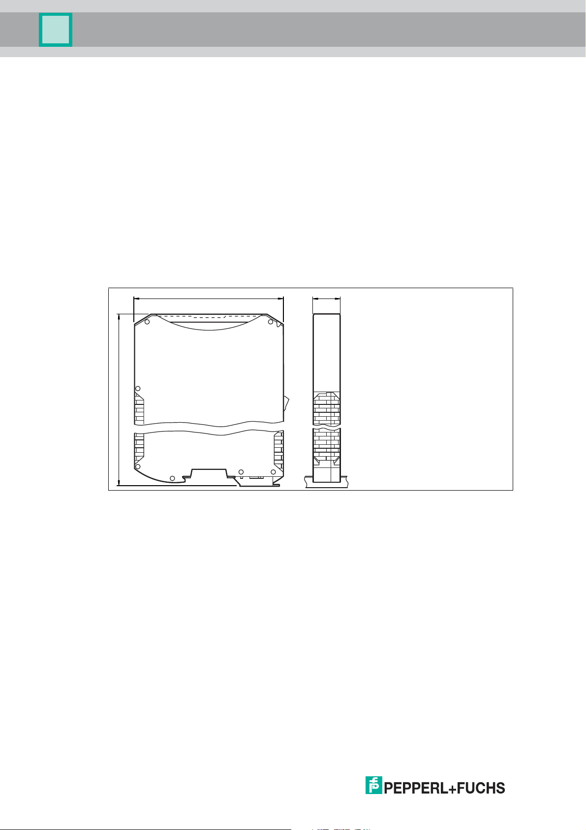
117
100
23
Product Description
2 Product Description
2.1 Use and Application
The WCS-PN G210 interface module acts as an interface between the WCS reader and the
PROFINET IO controller. The device has two PROFINET ports. The second port can be used,
for example, as an outgoing PROFINET port. The data between the WCS reader and WCSPNG210 is transmitted via an RS-485 interface. The data from the WCS-PNG210 to the
controller is transmitted via the PROFINET protocol.
You can connect a maximum of four WCS readers of type LS221 (and/or LS121) to one WCSPNG210 interface module. If you connect several WCS readers, they must have different
addresses. The number of connected WCS readers is configured in the hardware project
settings.
2.2 Dimensions
The interface module housing has the following dimensions.
Figure 2.1 Dimen sions
2018-03
6
Page 7
WCS-PNG210
3
4
5
6
2
1
Product Description
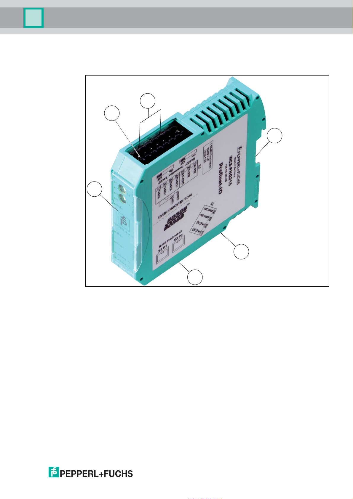
2.3 Design of the Device
Device Components
Figure 2.2 Interface module overview
1 X1: RS-485 interface
2 RS-485 bus termination slide switch
3 Mounting bracket
4 X2: Connection for power supply
5 X3: PROFINET IO comm unication interface
6 Front panel with rotary coding switches and indicator lights
2018-03
7
Page 8
WCS-PNG210
Power/State
1
2
4
8
S4
S5
State
WCS-PNG210 Modul
A
B
C
D
0
1
2
3
4
5
6
7
8
9
A
B
C
D
0
1
2
3
4
5
6
7
8
9
State
Power
Link/Act. P1
Link/Act. P2
PROFINET
Product Description
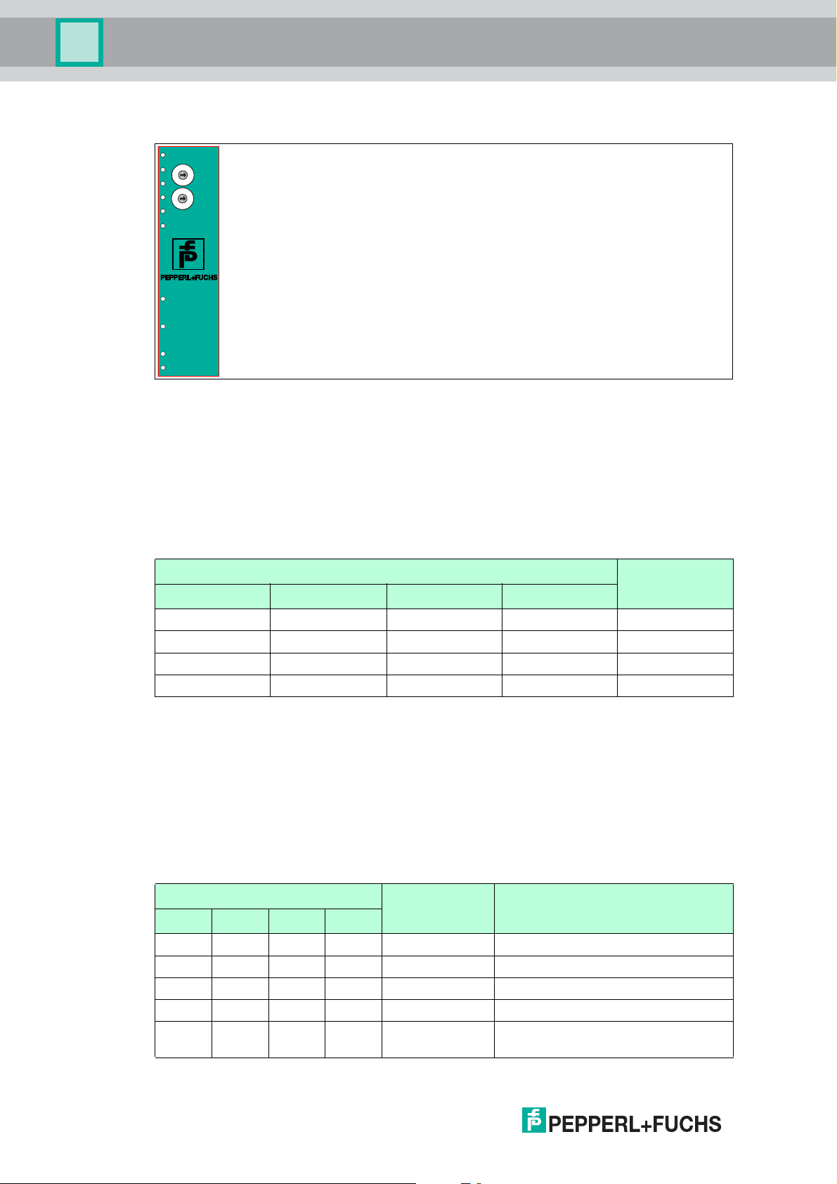
Front panel
Figure 2.3 Front panel overview
Power:
The "Power" LED is green: The WCS-PNG210 interface module is correctly connected to the
power supply.
State:
The "State" LED is green: Data exchange is taking place with the WCS readers. Using the four
"Error No/Select ID" LEDS, the number of the currently polled WCS reader is displayed.
ErrorNo/Select ID Reader address
8 4 2 1
0 0 0 1 0
0 0 1 0 1
0 1 0 0 2
1 0 0 0 3
Table 2.1 Display of the four LEDs "Erro r No/Select ID " when the "State" LED lights up green
The "State" LED is red: The interface module has detected an error or a warning. The interface
module displays the binar y coded error and/or warning number via the "Error No/Select ID"
LEDs.
Error (No. 1...5): Switch the interface module off and back on. If the error occurs
again, the module must be replaced.
Warning (No. 6...15): The warning provides information. The interface module displays
the warning for one m inute and then resets automatically.
ErrorNo/Select ID LED Error number Error description
LED8 LED4 LED2 LED1
0 0 0 0 0 Reserved
0 0 0 1 1 Hardware error
0 0 1 0 2 EEPROM error
0 0 1 1 3 Internal memory error
0 1 0 0 4 Fieldbus hardware error or incorrect
fieldbus ID
2018-03
8
Page 9

WCS-PNG210
Product Description
ErrorNo/Select ID LED Error number Error description
LED8 LED4 LED2 LED1
0 1 0 1 5 Script error
0 1 1 0 6 Reserved
0 1 1 1 7 Communication WCS reader, RS
1 0 0 0 8 Communication WCS reader, RS
1 0 0 1 9 Communication WCS reader, RS
1 0 1 0 10 General fieldbus error
1 0 1 1 11 Parity or fram e check error
1 1 0 0 12 Reserved
1 1 0 1 13 Fieldbus configuration error
1 1 1 0 14 Fieldbus data buffer overflow
1 1 1 1 15 Reserved
Table 2.2 Meaning of the error codes (four LEDs display "Error No/Se lect ID", if the "State" is
send buffer overflow
receive buffer overflow
timeout
illumin ated red and thus indicates an error or a warning )
Rotary coding switches S4 and S5
The two switches control the operating modes. Ensure that the two switches are at position 0
to enable the data exchange mode.
PROFINET State:
LED "PROFINET State" PROFINET interface state
Lights up green Data exchange in progress
Flashes green PROFINET is initialized, waiting for connection with IO controller
Lights up red Error with PROFINET hardware
Flashes red Error during PROFINET initialization
Table 2.3 "PROFINET State" LED display
PROFINET Power:
The "PROFINET Power" LED is green: The LED is connected directly to the electrically isolated
supply voltage of the PROFINET side.
PROFINET Link/Activity P1:
The "Link/Activity" LED on port 1 is controlled directly by the PROFINET processor and is
green if the Ethernet link pulses are found. When there is data traffic on the network, the LED
flashes green at the same speed as the sent/received data.
PROFINET Link/Activity P2:
The "Link/Activity" LED on port 2 is controlled directly by the PROFINET processor and is
green if the Ethernet link pulses are found. When there is data traffic on the network, the LED
flashes green at the same speed as the sent/received data.
2018-03
9
Page 10

WCS-PNG210
2
1
Installation
3 Installation
3.1 Mounting
Mounting the modules
The module is fastened to a DIN mounting rail with a width of 35 mm using a snap-on fixing
method.
Figure 3.1 Mounting
1. Hook the module (1) into the DIN mounting rail (2) from above and press it down until it snaps
into place.
The module is mounted.
Note!
Heat dissipation
You may place other modules to the left and right of the module.
Above and below the modules, there must be at least 5 cm of free space for heat dissipation.
2. You must connect the DIN mounting rail to the sw itch cabinet's equipotential busbar. The
connection wire must have a cross section of at least 10 mm2.
Note!
Vertical installation
You can also install the DIN mounting rail vertically, so that the modules can be rotated by 90°
for mounting.
2018-03
10
Page 11
WCS-PNG210
Reading head
PROFINET
Interface
WCS.-LS221
WCS-PNG210
RS 485 -
RS 485 +
24 V (Pwr)
0 V (Pwr)
X2-1
X2-2
X1-4
X1-5
X1-6
X1-7
SUB
GND
SDA
SDB
GND UB+
PE
PE
PROFINET
2. Port
Ethernet
RJ45
1. Port
Ethernet
RJ45
UB+
GND
RS 485+
RS 485-
Installation
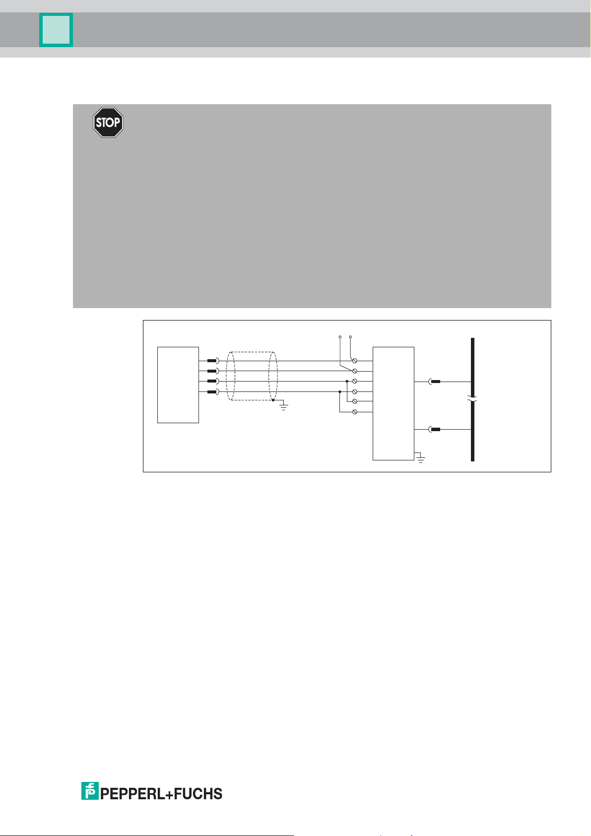
3.2 Electrical connection
Danger!
Device damage due to incorrect installation
A faulty installation of cables and connection lines can endanger the function and the electrical
safety of the device.
■
Note the permissible core cross section of the conductor.
■
If you are using stranded conductors, make sure that these stranded conductors are
crimped with wire end ferrules.
■
Make sure that conductors are insulated all the way up to the terminal.
■
Observe the tightening torque for the screws on the terminal. The tightening torque is
0.5 Nm.
■
Using an inappropriate tool may damage the screw heads. Use a slot-head screwdriver of
size 3.5 x 0.5.
■
Connecting an alternating current can damage the device or cause the device to
malfunction. Connect the device to direct current (DC).
Figure 3.2 Electrical connection
Plug X1 is located on the top side of the interface module, plug X2 on the underside.
Connection technology
You must/may use the following connection technology when wiring the assembly:
■
Standard screw/plug connection (supply + RS)
■
8-pin RJ45 connector (PROFINET IO connection)
In the case of the standard screw terminals, one line per connection point can be clamped. To
tighten the screws, use a screwdriver with a blade width of 3.5 mm.
Permissible cable cross section:
■
Flexible cable with wire end ferrule: 1 x 0.25 ... 1.5 mm
■
Solid cable: 1 x 0.25 ... 1.5 mm
2
The plug-in terminal strip represents a combination of standard screw connections and plug
connectors. The plug connector is coded and can therefore not be plugged in incorrectly.
2018-03
2
11
Page 12
WCS-PNG210
Installation
Connecting the power supply
Connect the operating voltage (10 VDC...30 VDC ) to terminals 1 and 2 of the 4-pin plug X2 on
the interface module. In addition, note the label on the module.
The "Power" LED lights up green.
Terminal Description
1 UB (Pwr) Operating voltage interface module/
2 0 V (Pwr) Ground interface module/ground WCS reader
3 Not used Not used
4 Not used Not used
Table 3.1 Termin al X2
Equipotential bonding connection
The connection to equipotential bonding occurs automatically when attaching to the DIN
mounting rail.
operating voltage WCS reader
PROFINET IO communication interface
This interface can be found on the m odule in the form of two 8-pin RJ45 sockets on the bottom
of the housing.
Insert the PROFINET connector into the RJ45 socket(s) with the label "RJ45 PROFINET IO".
Note!
Ensure that the cable length to the neighboring Ethernet nodes is at least 0.6 m.
Preparing to use the RS-485 interface
For operation on an RS-485 interface, the terminal on connector X1 must be connected as
follows:
1. Connect terminal 4 "Rx 422+" to terminal 6 "Tx 422+".
2. Connect terminal 5 "Rx 422-" to terminal 7 "Tx 422-".
Terminal Description
4 Rx 422+ RS-485+ data line to WCS reader
5 Rx 422- RS-485- data line to WCS reader
6 Tx 422+ Connect terminal 6 "Tx 422+" to terminal 4 "Rx 422+"
7 Tx 422- Connect terminal 7 "Tx 422-" to terminal 5 "Rx 422-"
Table 3.2 Termin al X1
12
2018-03
Page 13

WCS-PNG210
*) RS485-Termination:
Rx422 = o
Tx422 = on
1
2
3
4
5
6
7
Rx232
Tx232
AP-GND
Rx422+
Rx422-
Tx422+
Tx422-
RS485+
RS485-
Rx422* Termination Tx422*
On O On O
X1
Installation
Note!
RS-485 bus termination
If the interface module is operated as the first or last physical device in an RS-485 bus, there
must be a bus term ination on this module. To do this, set the slide switch "Rx 422 Termination"
to "Off" and the slide switch "Tx 422 Termination" to "On". This activates the RS-485 terminator
(150 Ω) built into the interface module.
If you only connect one WCS reader to the interface module, you must always activate the RS485 terminator, see also Cable routing in the RS-485 bus.
2018-03
13
Page 14
WCS-PNG210
4
3
2
1
Installation
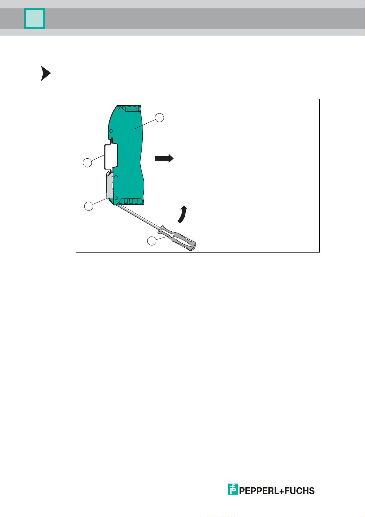
3.3 Dismounting
Dismounting the modules
Use a suitable slot-head screwdriver for dismounting the module.
1. Disconnect all the supply and signal lines.
Figure 3.3 Dismoun ting
2. Insert the screwdriver (2) into the groove of the mounting bracket (3).
3. Press the screwdriver (2) in the specified direction until the lock on the DIN mounting rail (4)
opens, see figure.
4. Then press the module (1) upwards and lift it out of the DIN mounting rail.
2018-03
14
Page 15

WCS-PNG210
Commissioning
4 Commissioning
4.1 Introduction
Warning!
Danger to life due to defective work
Errors during installation and commissioning can cause life-threatening injuries and significant
property damage.
■
Installation and commissioning m ay only be carried out by trained personnel in
accordance with the safety regulations.
Components
To commission the m odule, you require the following components:
■
WCS-PNG210 interface module
■
Connection cable from the interface module to the reader
■
Connector for the PROFINET connection to the interface module
■
Ethernet cable
■
10 VDC...33 VDC power supply
■
GSDML file (the GSDML file can be obtained free of charge from our website
www.pepperl-fuchs.com).
Connecting the interface module
To ensure that the assembly functions correctly, you must carry out the following steps during
commissioning:
1. Assign a PROFINET address.
Note!
On delivery, the module does not yet have an IP address. In normal operation, the IP address is
usually assigned to the module by the PROFINET IO controller (PLC).
2. Assign a PROFINET device name.
Note!
On delivery, the module does not yet have a device name. The device name is assigned to the
gateway via the project planning software.
3. Connect the module to PROFINET using the interface labeled "RJ45 PROFINET IO".
4. To commission the process equipment (reader), please refer to its manual.
5. Ground the DIN mounting rail onto which the assembly is snapped.
6. Connect the direct current to the terminals provided.
7. Use any planning tool for project planning. The GSDML file can be downloaded from our
website: ww w.pepperl-fuchs.com. Simply enter the product name or item number in the
Product/Keyword search box and click Search.
Note!
A more detailed description of the procedure for the individual steps is provided on the
following pages.
2018-03
15
Page 16

WCS-PNG210
Commissioning
4.2 Connecting WCS readers
If you connect several WCS readers to one interface module, the WCS readers must have
different addresses. This will allow the programmable logic controller to allocate the data to the
correct WCS readers. If you only connect one WCS reader to an interface module, this WCS
reader always receives the address 0. You can connect up to four WCS readers to an interface
module via an RS-485 cable. On delivery, the default address of each WCS reader is 0. Refer
to the configuration instructions for the WCS reader if you need to change the address of the
WCS reader.
WCS reader terminal pin
2 2 1 1 X2-1
4 4 2 2 X1-4
1 1 3 4 X1-5
3 3 5 3 X2-2
Table 4.1 Connecting the WCS reader(s)
Interface module terminalWCS2A WCS2B WCS3A WCS3B
Setting the number of connected WCS readers
Set the number of connected WCS readers in the hardware project settings, see chapter 4.4.
4.3 Connecting the WCS-PNG210 to the network
The connection to the PROFINET IO is made via the two "RJ45 PROFINET IO" sockets on the
underside of the interface module. The front socket is labeled "X3 P1", and the rear socket is
labeled "X3 P2".
Pin assignment X3 P1 & X3 P2
Terminal Designation
1 TD+ Transmission line +
2 TD- Transmission line -
3 RD+ Receive line +
4 n.c. Not connected
5 n.c. Not connected
6 RD- Receive line -
7 n.c. Not connected
8 n.c. Not connected
Table 4.2 Termin als of the 8-pin "RJ45 PROFINET IO" sockets
Note!
The cable to the surrounding modules on the Ethernet line must be at least 0.6 m long.
16
Connecting the device to the controller
Plug the PROFINET connector into the RJ45 socket. Use a Cat. 5 data cable.
Setting data exchange mode
Set the "S4" and "S5" rotary switches to position 0.
2018-03
Page 17

WCS-PNG210
Commissioning
4.4 Integrating WCS-PNG210 into the network
Caution!
Malfunction due to incorrectly configured devices
Incorrectly configured devices can cause malfunction of the plant.
■
Only put devices into operation after they have been configured correctly.
To operate the module described in this manual, you will need a GSDML file. The GSDML file
must be imported into the corresponding configuration tool prior to commissioning the module.
The GSDML file can be downloaded from our website: www.pepperl-fuchs.com. Simply enter
the product name or item number in the Product/Keyword search box and click Search.
Select your product from the list of search results. Click on the information you require in the
product information list, e.g., Software.
A list of all available downloads is displayed.
PROFINET address assignment
On delivery, the interface m odule does not yet have an IP address. In normal operation (data
exchange mode), the IP address is usually assigned to the module by the PROFINET IO
controller (PLC). For this purpose, the module has a device name that is used to address it.
PROFINET device name
On delivery, the module does not yet have a device name. The device nam e is assigned to the
module via the project planning software. The following rules from the PROFINET specification
apply to the device name:
■
It consists of one or more name parts separated by a dot
■
The total length is 1 to 240 characters.
■
The length of a name part is between 1 and 63 characters.
■
A name part consists exclusively of lowercase letters, numbers, and the hyphen.
■
Neither the first nor the last character of a name part is a hyphen.
■
The first part of the name does not begin with "port-xyz" or "port-xyz-abcde", where a, b,
c, d, e, x, y, and z are digits.
■
It does not have the form "k.l.m.n", where k, l, m, and n are numbers between 0 and 999.
Note!
Various configuration tools are available to allow you to configure the interface module. This
manual describes how to configure a Siemens SIMATIC controller as an example. If you are
using a PLC from a different manufacturer, the process is similar to the one described here.
2018-03
17
Page 18
WCS-PNG210
Commissioning
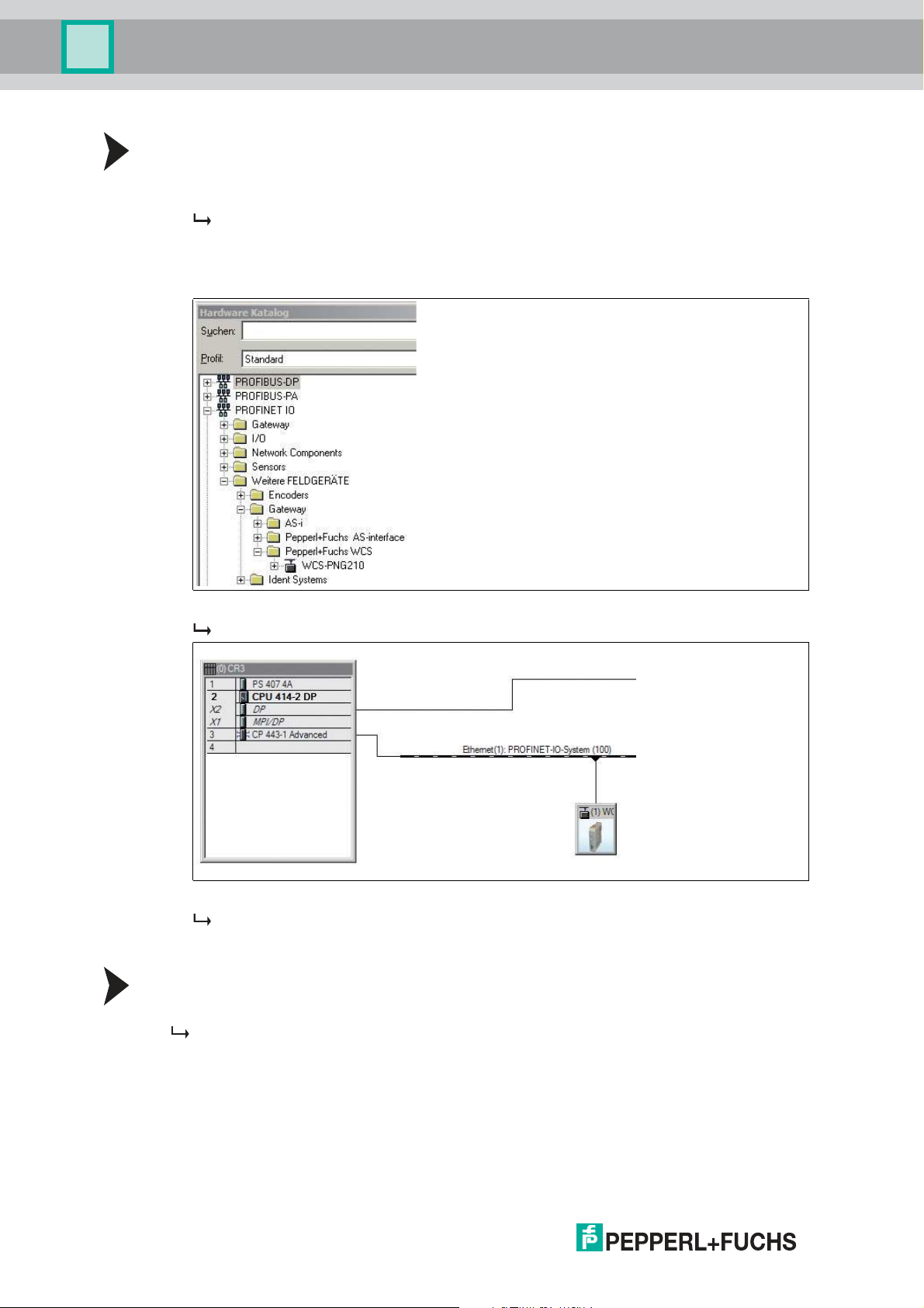
Adding the device to the network
1. Open SIMATIC Manager and select the PROFINET IO system.
2. Install the GSDML file by clicking on Options and then Install GSD File.
The device data is added to the hardware catalog.
3. Open the hardware catalog and browse through the tree structure until you see a WCSPNG210 symbol (PROFINET IO > Additional Field Devices > Gateway > Pepperl+Fuchs
WCS).
4. Drag the WCS-PNG210 from the tree structure and drop it into your PROFINET IO system.
The symbol for the WCS-PNG210 is shown in the PROFINET IO system.
5. Double-click on the device symbol.
The Properties window opens.
6. Enter the required network configuration.
Searching for a device on the network
To see which devices are on the network, click on Browse in the Edit Ethernet Node window.
The PLC interrogates the network to see which PROFINET nodes are present (Broadcast
query). A list of the connected devices is displayed in the window.
18
2018-03
Page 19

WCS-PNG210
Commissioning
Changing the device name
Note!
The PLC must not communicate with the device via PROFINET while you are changing the
device name. An error message will be output if you try to change the device name while the
plant is in operation.
1. Stop PROFINET communication if it is active.
2. Select Pepperl+Fuchs WCS from the list of nodes and click on OK.
3. In the field Assign device name, enter the device name for the interface module. Click on
Assign Name.
The interface module is given the name you entered and can then be uniquely identified
by the PLC.
4. In the WCS module Properties window, enter the new device name and save the
configuration.
The PLC will recognize the name of the device and will be able to communicate with it.
Note!
An LED on the device can be made to flash using the configuration tools. If you have a number
of WCS-PNG210 interface modules on the network, this function will enable to you to uniquely
identify each device. Select the device from the list of Ethernet modules and click on Flash.
The "State" LED on the relevant WCS-PNG210 interface module will start to flash.
Depending on your application, select one, two, three, or four connected WCS readers and the
operating mode. When in the "only Position" operating mode, the WCS readers output their
position. In the "Position and Speed" operating mode, the WCS readers output their position
and the speed at which they are currently moving.
Regardless of the number of WCS readers, 1 byte is reserved for querying the diagnosis of the
WCS readers in the master. For the response data, 4 bytes are reserved per WCS reader in the
"only Position" operating mode (configuration data for 4 WCS readers: 0x20, 0xD1, 0xD1,
0xD1, 0xD1). In the "Position and Speed" operating mode, 6 bytes are reserved per WCS
reader (configuration data for 4 WCS readers: 0x20, 0xD2, 0xD2, 0xD2, 0xD2).
2018-03
19
Page 20

WCS-PNG210
Commissioning
Setting the number of readers, operating mode, and addresses
1. Open the hardware catalog and browse through the tree structure until you see the WCSPNG210 symbol (PROFINET IO > Additional Field Devices > Gateway > Pepperl+Fuchs
WCS).
2. Click on + next to the WCS-PNG210 symbol to expand the tree structure.
3. Select the module with the appropriate number of readers and operating mode and drag it
into the window where the modules are listed.
The selected module is added to the list.
4. To change the input and output address of the module, double-click on the module and
enter the addresses in the Properties window.
5. Click on Transfer to transfer all the settings to the PLC.
4.5 Data format for modules
In "only Position" operating mode, 4 bytes are reserved for each WCS reader.
Bit 7 6 5 4 3 2 1 0
Byte 0 0 0 0 0 0 P18 P17 P16
Byte 1 P15 P14 P13 P12 P11 P10 P09 P08
Byte 2 P07 P06 P05 P04 P03 P02 P01 P00
Byte 3 0 0 0 DB ERR OUT A1 A0
Table 4.3 Data format for each conn ected WCS reader in "only Position" ope rating mode, reader
address = 0.. .3
20
2018-03
Page 21

WCS-PNG210
Commissioning
In "Position and Speed" operating mode, 6 bytes are reserved for each WCS reader.
Bit 7 6 5 4 3 2 1 0
Byte 0 0 0 0 0 0 P18 P17 P16
Byte 1 P15 P14 P13 P12 P11 P10 P09 P 08
Byte 2 P07 P06 P05 P04 P03 P02 P01 P 00
Byte 3 0 0 0 DB ERR OUT A1 A0
Byte 4 0 0 0 0 0 0 0 0
Byte 5 0 S06 S05 S04 S03 S02 S01 S00
Table 4.4 Data format for each connected WCS reader in "Position and Speed" operating mode,
Pxx: position data, P00 = LSB
Sxx: speed (in multiples of 0.1 m/s), S00 = LSB
Example: Byte 5 = 00011011 = 27, corresponds to 2.7 m/s
A1, A0: reader address, 00 = WCS reader address #1
DB: pollution display, 1 = cleaning necessary
OUT: code rail loss, 0 = code rail recognized
ERR: error display, error code (LEDs)
reader address = 0...3
Address bits A1 and A0
A1 A0 Reader address
0 0 Reader address 0
0 1 Reader address 1
1 0 Reader address 2
1 1 Reader address 3
Status bits
DB ERR OUT Description
0 0 0 Current position value binary coded in
P00...P18
0 0 1 WCS reader outside of the code rail,
not a position value
P0...P18=0: WCS reader partly
outside the code rail
P0=1, P2...P18=0: WCS reader
completely outside of the code rail
1 0 0 Current position value binary coded in
P00...P18
1 0 1 No position value, WCS reader
outside of the code rail
X 1 X No position value, error message from
WCS reader, error number binary
coded in P00...P18
Optical state of WCS
reader
Good
Good
Poor
Poor
-
2018-03
21
Page 22

WCS-PNG210
Reading head
Interface or control
(PLC)
Appendix
5 Appendix
5.1 Cable Routing in the RS-485 Bus
The data cables must always form an in-line connection between the first and the last node.
This in-line connection must end with a terminator.
The RS-485 terminators are integrated in the WCS readers and can be switched on and off
with the interface module.
If only one WCS reader is connected, one device is connected at the beginning and one
device is connected at the end of the data line.
22
Figure 5.1 Connection o f one reading head
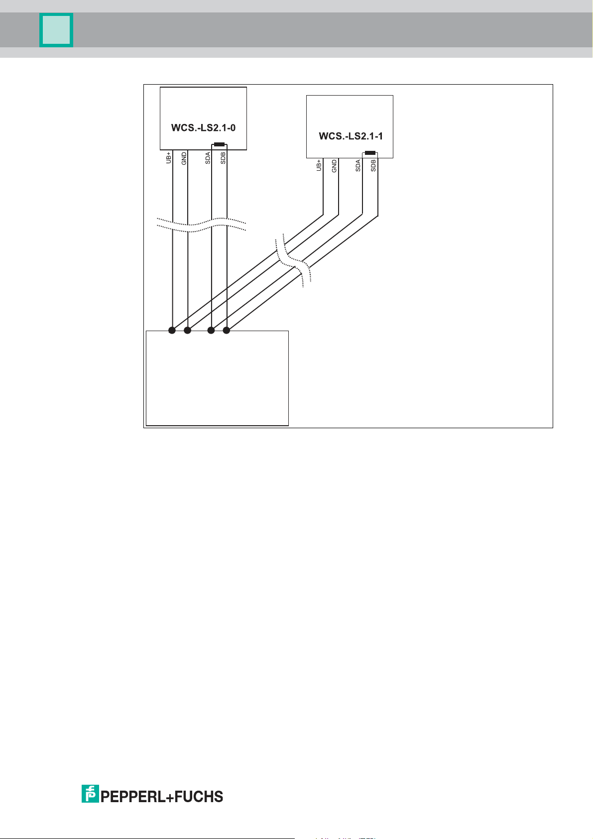
If two WCS readers are connected to one interface module, there are two wiring versions:
■
Version A:
One WCS reader is located at the beginning and one WCS reader at the end of the data
line. For both WCS readers, the RS-485 terminator is activated. The interface module is
located between these two readers and does not have an RS-485 terminator. Each WCS
reader is connected to the interface module by a separate data cable.
2018-03
Page 23
WCS-PNG210
Interface or control
(PLC)
Reading head
Reading head
Appendix
Figure 5.2 Connection of two reading heads, Version A
■
Version B:
The interface module is located at the beginning of the data line; one WCS reader is
located at the end of the data line. Both need the RS-485 terminator. The second WCS
reader is connected to the line connection between the interface module and the first
WCS reader through a short spur (length <1 m). Use a bus terminal to connect the spur.
2018-03
23
Page 24

WCS-PNG210
Reading head
Reading head
Interface or control
(PLC)
Spur line (max. 1 m)
Bus terminal
Appendix
Figure 5.3 Connection o f two reading heads, Version B
The wiring version used depends on w hich is best suited for the application. If three or four
WCS readers are used on the same interface module, connect these using spurs as shown in
variant B.
24
2018-03
Page 25

WCS-PNG210
Appendix
5.2 Data Cables and Accessories
RS-485 data cable
For the RS-485 data transfer path, a four-wire, shielded, twisted pair data cable must be used.
One wire pair is used for the supply voltage, and one pair for the RS-485 data connection. The
maximum length of the cable depends on the data transfer capacity of the data cable—corecore—and on the cross section of the cables for power supply of the WCS readers. For data
transfer, a small core cross section, and thus small cable capacitance is an advantage,
whereas for the power supply the largest possible cross section is required. The table below
shows the possible cable lengths depending on the cable cross section.
In the calculations, the worst-case scenario was assum ed: All WCS readers are located at the
end of the data line. In the case of large cable lengths, and when connecting multiple WCS2
readers with heating, six-wire data cable (3 x 2) can be used. These data cables use two pairs
for the power supply (doubling the cable cross section), and one pair for the RS-485 data line.
Capacitance (corecore)
60 pF 500 m 500 m 300 m
90 pF 500 m 450 m 275 m
120 pF 500 m 400 m 250 m
The table shows the possible cable lengths depending on the cable capacitance (core-core).
The number of connected WCS readers is of no significance.
RS-485 interface
19.2 KB (LS246) 62.5 KB (LS221) 187.5 KB (LS211)
WCS-DCS / WCS-DCF data cables
There are 2 types of data cable available:
. WCS-DCS for stationary cable routing
. WCS-DCF for trailing cable and drag chain installations.
The data cables are twisted pairs and have a tinned copper braided shield. The braided shield
surrounds all wire pairs. The parameters of the data cable for RS-485 and SSI data transfer
applications are listed in the table below.
WCS-DCS WCS-DCF
Capacitance (core-core) 95 pF/m 60 pF/m
Cross section
Number of wires 6 (3 x 2) 6 (3 x 2)
External diameter 5.8 mm 7.5 m m
Temperature range -30 °C ... 70 °C -40 °C ... 70 °C
Order designation WCS-DCS WCS-DCF
0.14 mm
2
0.25 mm
2
2018-03
25
Page 26

WCS-PNG210
Appendix
Single-ended female cordsets and adapter cables
Field-attachable female connectors M12 x 1
straight 4 6 mm – 8 mm V1-G-PG9
angled 4 6 mm – 8 mm V1-W-PG9
straight 5 6 mm – 8 mm V15-G-PG9
angled 5 6 mm – 8 mm V15-W-PG9
straight 6 6 mm – 8 mm V17-G-PG9
angled 6 6 mm – 8 mm V17-W-PG9 *)
Table 5.1 *) Cable outlet on top, not variable
Shielded connection cable with molded single-ended female cordset
straight 4 2 m V1-G-2M-PUR-ABG
straight 4 5 m V1-G-5M-PUR-ABG
angled 4 2 m V1-W-2M-PUR-ABG
angled 4 5 m V1-W-5M-PUR-ABG
straight 5 5 m V15-G-5M-PU R-ABG
angled 5 5 m V15-W-5M-PUR-ABG
straight 8 2 m V19-G-2M-PU R-ABG
straight 8 5 m V19-G-5M-PU R-ABG
Number of poles Cable diameter Order designation
Number of poles Cable length Order designation
26
2018-03
Page 27

FACTORY AUTOMATION –
SENSING YOUR NEEDS
Worldwide Headquarters
Pepperl+Fuchs GmbH
68307 Mannheim · Germany
Tel. +49 621 776-0
E-mail: info@de.pepperl-fuchs.com
USA Headquarters
Pepperl+Fuchs Inc.
Twinsburg, Ohio 44087 · USA
Tel. +1 330 4253555
E-mail: sales@us.pepperl-fuchs.com
Asia Pacific Headquarters
Pepperl+Fuchs Pte Ltd.
Company Registration No. 199003130E
Singapore 139942
Tel. +65 67799091
E-mail: sales@sg.pepperl-fuchs.com
www.pepperl-fuchs.com
Subject to modifications
Copyright PEPPERL+FUCHS • Printed in Germany
/ TDOCT5839__ENG
03/2018
 Loading...