

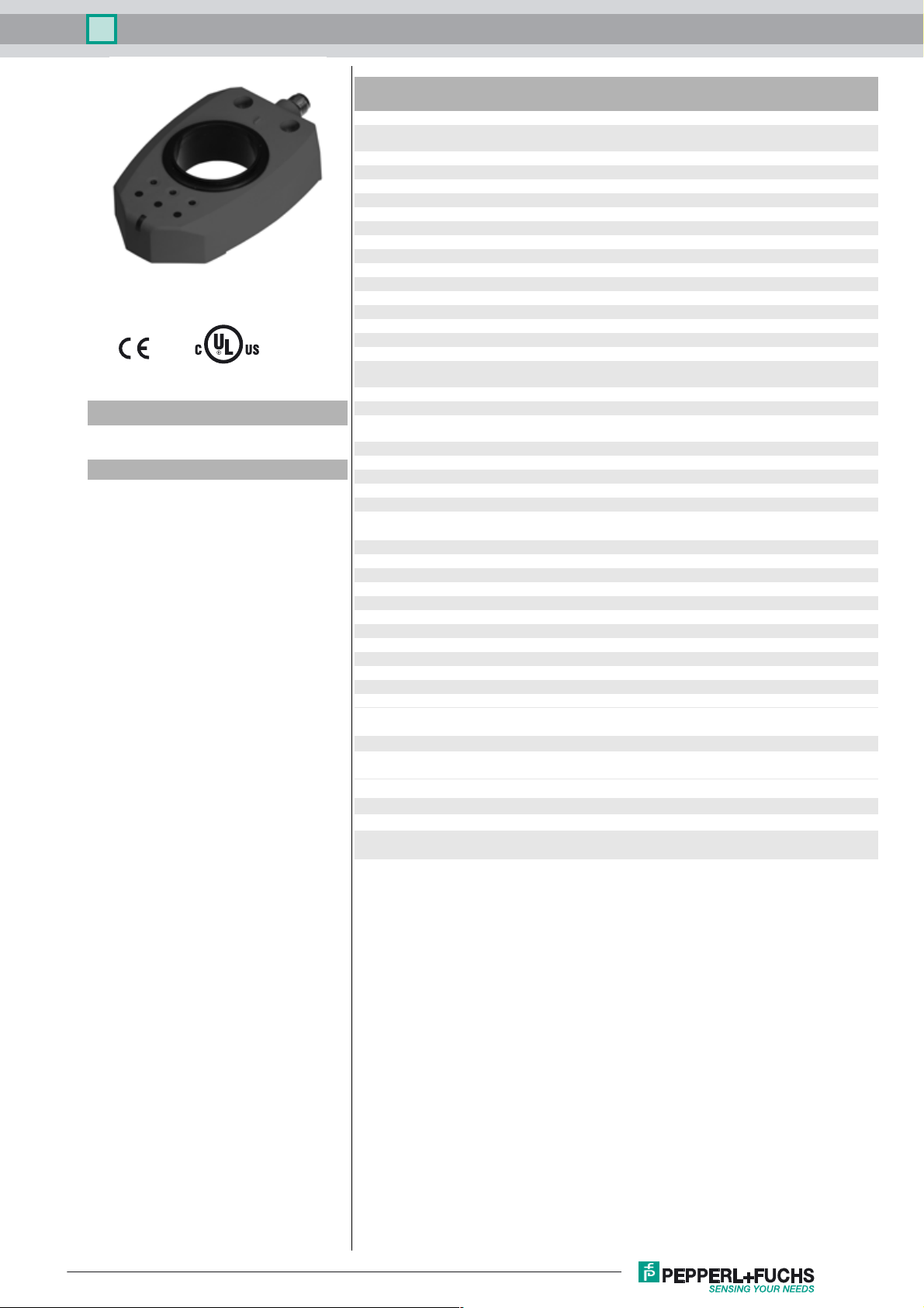
Ind. angular measuring system PMI90DV-F130-I2E2-V15
Technical data
General specifications
Model Number
PMI90DV-F130-I2E2-V15
Features
• Analog position indicator with end
position monitoring
• 2 configurable switching frames
• Preset range of angle measurement 0 ... 90°
• Extended analog signal range
Measurement range max. 180°
Adjustment range 180° , 2 switch frames programmable
Nominal ratings
Operating voltage U
Reverse polarity protection reverse polarity protected
Repeat accuracy ± 0.25 °
Resolution 0.2 °
Temperature drift 0.02 ° / °C (-25 °C ... 70 °C)
No-load supply current I
Functional safety related parameters
MTTFd 234 a
Mission Time (T
Diagnostic Coverage (DC) 0 %
Indicators/operating means
LED yellow 1 switching state, Switching output 1
LED yellow 2 switching state, Switching output 2
LED PWR/ERR status display LED, green/red (Power on / missing actuator /
LED I Activator within measuring range
Switching output
Output type 2 switch outputs PNP, NO , reverse polarity protected ,
Operating current I
Switching hysteresis 1 °
Voltage drop ≤ 3 V
Short-circuit protection pulsing
Analog output
Output type current output
Linearity error ± 1.5 ° , (with original actuator)
Transfer characteristics
Internal measurement cycle 30 ms
Ambient conditions
Ambient temperature -25 ... 70 °C (-13 ... 158 °F)
Mechanical specifications
Connection type 5-pin, M12 x 1 connector
Degree of protection IP67
Material
Housing PBT
Target mild steel, e. g. 1.0037, SR235JR (formerly St37-2)
Mass 180 g
Compliance with standards and
directives
Standard conformity
Standards EN 60947-5-2:2007
B
0
) 20 a
M
L
min. 90°
18 ... 30 V DC
≤ 45 mA
keylock)
short-circuit protected , programmable
≤ 100 mA
3.8 ... 20.5 mA (R
IEC 60947-5-2:2007
< 400 Ω)
L
Release date: 2014-08-19 09:41 Date of issue: 2014-08-19 239077_eng.xml
Refer to “General Notes Relating to Pepperl+Fuchs Product Information”.
Approvals and certificates
UL approval cULus Listed, General Purpose, Class 2 Power Source
CCC approval CCC approval / marking not required for products rated
≤36 V
1
Ind. angular measuring system PMI90DV-F130-I2E2-V15
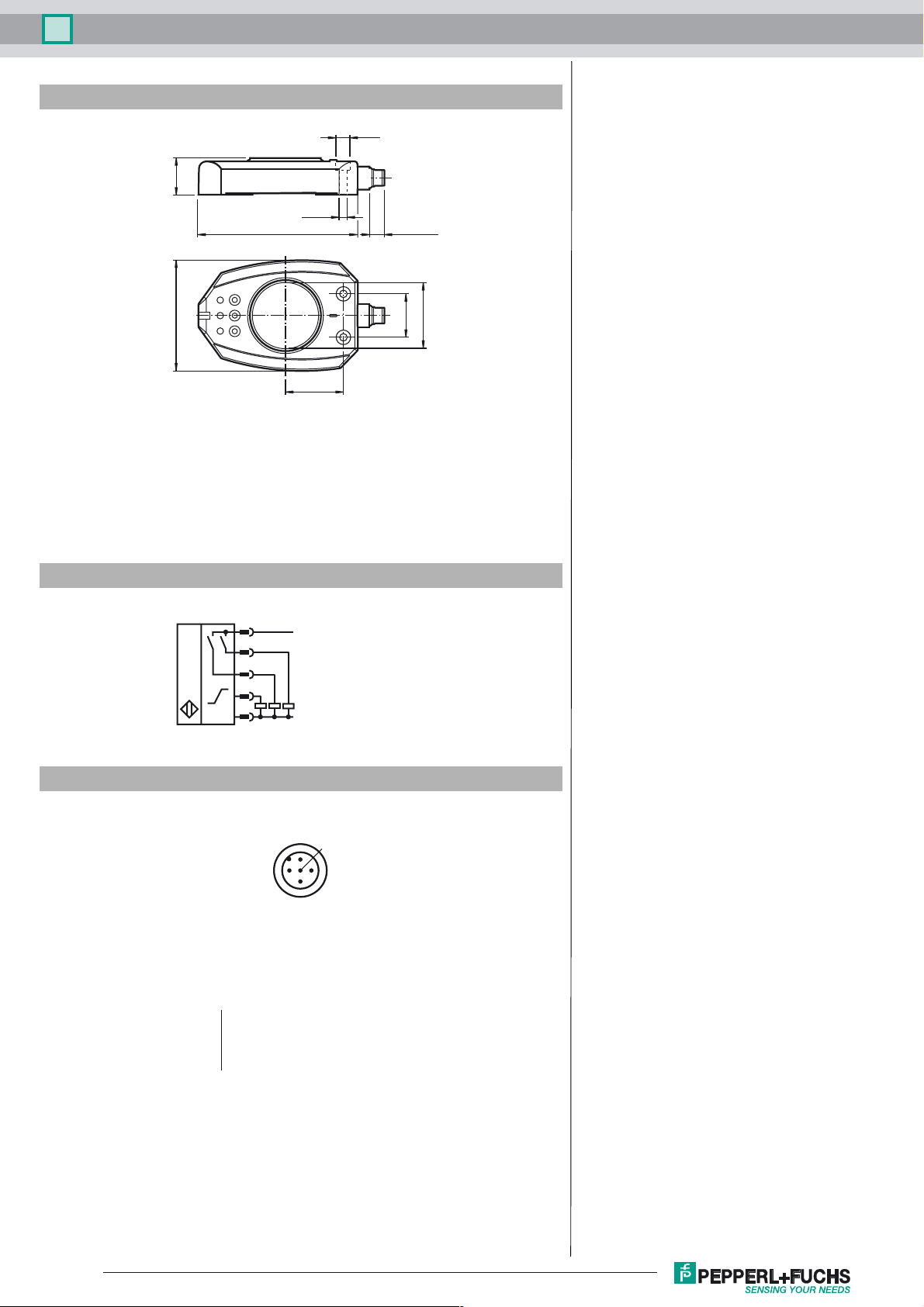
Dimensions
ø 10
26
ø 5.2
110 10.3 ± 0.3
76.5
Electrical Connection
30
ø 41.5
40
1
4
2
5
3
L+
S1
S2
I
L-
Pinout
1
5
2
Wire colors in accordance with EN 60947-5-2
1 BN
2 WH
3 BU
4 BK
5 GY
(brown)
(white)
(blue)
(black)
(gray)
4
3
Release date: 2014-08-19 09:41 Date of issue: 2014-08-19 239077_eng.xml
Refer to “General Notes Relating to Pepperl+Fuchs Product Information”.
2

Ind. angular measuring system PMI90DV-F130-I2E2-V15
Accessories
BT-F130-A
Actuator for F130 series
V15-G-2M-PVC
Female cordset, M12, 5-pin, PVC cable
V15-W-2M-PVC
Female cordset, M12, 5-pin, PVC cable
Functional Description
The inductive angular positioning system is a measuring system designed to detect the angular position of valve actuators and valves. The system is equipped with an analog output I (4 mA ... 20 mA) for continuous position detection, as well as two switching outputs (S1 and S2) for monitoring the end position.
Actuator BT-F130-A is normally attached to the rotary system component to detect the position. This actuator rotates in the central hole on the
sensor and contains the metal insert required for detecting the position. The component is optimally adapted to the mechanical requirements of
valves and valve actuators.
Factory Default Setting
The sensor is set at the factory to monitor a range of 0° ... 90°. Switching output S1 is positioned at 0°; switching output S2 is positioned at 90°.
The switching range of both switching outputs is ± 6° around the relevant switching point.
The analog ouput has a power reserve from -30° to +30 beyond the measuring range. The lower trip value of the power reserve (-30°) is 3.8 mA.
The upper trip value of the power reserve (+30°) is 20.5 mA. Beyond this power reserve, an output current of 3.6 mA is adopted.
Behavior of the current output at a measuring range of 90°:
0° 90° 120° 180° 270° 330° 0°
3.8 mA ... 20.5 mA
3.8 mA ... 20.5 mA
Direction of rotation
3.6 mA
Direction of rotation
3.6 mA
3.8 mA ... 20.5 mA
3.8 mA ... 20.5 mA
Programming the Measuring System (General)
For best results when adjusting the process, the measuring system can be programmed using keys S1, I, and S2. If the keylock is active, it must
first be deactivated. The sensor indicates that the keylock is active by changing the color of the "Power/Error" LED to red when a button is
pressed. To unlock the buttons, press and hold the S1 and S2 buttons simultaneously for 3 seconds. The color of the "Power/Error" LED changes
to green. The buttons are no longer locked.
Note:
When programming the monitoring area (analog output), the switching points of the two switching outputs (S1 and S2) are always automatically
adopted from the start and end point of the monitoring area. If different switching points or switching windows need to be programmed, this step
must always be performed after the monitoring area has been programmed.
Programming the Monitoring Area
The monitoring area represented by the analog output can be programmed within a range of 90° ... 180°.
1. Press and hold the I key for > 2 seconds. The flashing yellow LED I indicates that the device is ready for the start point of the analog ramp
to be programmed.
2. Move the actuator to the position you wish to define as the start point of the analog ramp. Then press the I key. The yellow LED I lights up
for 2 seconds and then starts to flash again. This indicates that the device is ready for the end point of the analog ramp to be programmed.
3. Move the actuator to the position that you wish to define as the end point of the analog ramp.
Note:
When the actuator rotates, the first 30° define the direction of rotation of the measurement range in which the values of the analog output
increase (clockwise/counterclockwise).
4. Briefly press the I key. The setting is then stored in the nonvolatile memory of the sensor. The yellow LED I then lights up continuously to
indicate that programming was successful.
The entire signal range (4 mA ... 20 mA) of the analog output is scaled to the programmed angle segment.
Note: Programming a 90° Angle Segment
If an angle segment of 90° is to be programmed for the analog output, you can capitalize on the fact that the angle segment must be a minimum
of 90°. In this instance, when programming the angle segment (step 3), move the actuator to a position that is less than 90° but greater than 30°
in relation to the starting position. When this position is confirmed by pressing the relevant key, the sensor automatically calculates and stores
the position value for 90°.
Note: Programming a 180° Angle Segment
If an angle segment of 180° is to be programmed for the analog output, you can capitalize on the fact that the angle segment must be a maximum
of 180°. In this instance, when programming the angle segment (step 3), you can move the actuator to a position that is greater than 180° in relation to the starting position. When this position is confirmed by pressing the relevant key, the sensor automatically calculates and stores the
position value for 180°.
Programming Different Switching Windows
The switching windows of the two switching outputs (S1 and S2) can be configured within the monitoring area as required. The process for programming the switching window for switching output S1 is described here as an example. The switching window for switching output S2 is programmed in exactly the same way, just using the S2 key.
1. Press and hold the S1 key for > 2 seconds. The flashing yellow LED indicates that the device is ready for the start point of the switching
Release date: 2014-08-19 09:41 Date of issue: 2014-08-19 239077_eng.xml
Refer to “General Notes Relating to Pepperl+Fuchs Product Information”.
3

Ind. angular measuring system PMI90DV-F130-I2E2-V15
window for switching output S1 to be programmed.
2. Move the actuator to the position you wish to define as the start point of the switching window for switching output S1.
3. Briefly press the S1 key. The yellow S1 LED lights up for 2 seconds and then starts to flash again. This indicates that the device is ready for
the end point to be programmed.
4. Move the actuator to the position you wish to define as the end point of the switching window for switching output S1.
Note:
At the end of programming, the area covered by the actuator will be the angle range in which the switching output is active.
5. Briefly press the S1 key. The setting is then stored in the nonvolatile memory of the sensor. The yellow S1 LED then lights up continuously
to indicate that programming was successful.
Note:
If, in the time that elapses between the start and end points of the switching window being programmed, the actuator does not move, the smallest
possible switching window is programmed with a width of ± 2.5° around the actuator.
Note:
If the start or end point of the switching window is less than 6° from the start or end of the monitoring area, the start or end point of the switching
window is automatically set at 6° past the edge of the monitoring area.
Example: The edge of the monitoring area is set at 90°. You program the start of the switching window at 60° and the end of the switching window
at 85°. In this case, the switching range will extend from 60° to 96°.
Activating the keylock
The keylock is not activated initially. Press any button on the sensor briefly to determine whether the keylock is active. If the color of the "Power/
Error" LED remains green, the keylock is inactive and if the color of the "Power/Error" LED changes to red, the keylock is active. To activate the
keylock, press and hold the S1 and S2 keys simultaneously for 3 seconds. The color of the "Power/Error" LED changes to red.
Using a different actuating element
You can use a different actuator instead of the BT-F130-A actuator provided, which must be positioned centrally in the sensor opening. When using a different actuating element, the element must fulfill all requirements relating to the material, dimensions and distance to the sensitive surface on the sensors (see table). Failing to
fulfill all of these requirements may reduce the accuracy/resolution of the sensor or even cause the sensor to stop functioning.
Dimensions when using a different actuating element
d2
d1
t
C
L
A
B
D
w
d3
E
A Drive shaft
B Insulation ring made from non-conductive material
C Separate actuator (L ≥23 mm)
D Sensitive surface on the sensors (black, cylindrical inner surface)
E Sensor
Actuator (C) can be placed on the insulating ring made from non-conductive material (B) or inserted
in this ring.
Dimension
t2 mm
w7.5 mm
L ≥ 23mm
d1 Depending on the drive shaft material
d2 Select so that the distance between the edges of the act uator and the sensitive
d3 41.5 mm
Actuator material Mild steel such as S235JR+AR (previously St37-2)
S235JR+AR (previously St37-2): max. 19 mm
Stainless steel 1.4435 / AISI 316L (V4A): max. 21 mm
Stainless steel 1.4305 / AISI 303 (V2A): max. 23 mm
surface on the sensor is 1 ... 2 mm.
Release date: 2014-08-19 09:41 Date of issue: 2014-08-19 239077_eng.xml
Refer to “General Notes Relating to Pepperl+Fuchs Product Information”.
4
 Loading...