

Pepperl Fuchs PMI40-F90-IU-IO-V15 Data Sheet
Inductive positioning system PMI40-F90-IU-IO-V15
Technical Data
General specifications
Switching element function Analog current or voltage output, programmable
Object distance 0.5 ... 3 mm , recommended: 1.5 mm
Measurement range 0 ... 40 mm
Linearity range 1 ... 39 mm
Nominal ratings
Model Number
PMI40-F90-IU-IO-V15
Features
• Parameterization and diagnosis via IOLink
• Measuring range 0 ... 40 mm
• Parameterisable measuring range
• Analog current or voltage output,
programmable
Application
Attention!
If the sensor is supplied via an IO-Link-Master, ensure that the sum of the no-load supply
current and operating currents of all sensor
outputs does not exceed the maximum current the IO-Link-Master can supply.
Accessories
BT-F90-W
Damping element for sensors of type F90, F112, and F166;
side hole
MH-F90
Mounting bracket for mounting of F90 sensors
V15-G-2M-PVC
Female cordset, M12, 5-pin, PVC cable
V15-W-2M-PVC
Female cordset, M12, 5-pin, PVC cable
Operating voltage UB12 ... 30 V DC
Reverse polarity protection reverse polarity protected
Linearity error within measuring range: ± 0.8 mm
Repeat accuracy R ± 0.1 mm
Resolution 50 µm
Temperature drift ± 0.5 mm (-25 °C ... 70 °C)
No-load supply current I
Operating voltage indicator LED green
Functional safety related parameters
MTTFd 365 a
Mission Time (T
Diagnostic Coverage (DC) 0 %
Indicators/operating means
LED S3 Damping element in the configured analog measuring range
LED STATUS Status display LED, green/red (Power on, communication/error,
Interface
Interface type IO-Link (via C/Q = Pin 4)
Device profile Smart Sensor
Transfer rate COM 2 (38.4 kBaud)
Value range 0000h ... 3200h
IO-Link Revision 1.1
Min. cycle time 2.3 ms
Process data witdh Process data input: 16 Bit
SIO mode support yes
Device ID 0x200201 (2097665)
Compatible master port type A
Analog output
Output type current output 4-20 mA voltage output 0 - 5 V DC 0 ... 10 V DC ,
Load resistor current output: ≤ 400 Ω
Short-circuit protection voltage output: current limit
Ambient conditions
Ambient temperature -25 ... 85 °C (-13 ... 185 °F)
Mechanical specifications
Connection type 5-pin, M12 x 1 connector
Degree of protection IP67 / IP69K
Material
Housing
Target
Mass 56 g
Compliance with standards and
directives
Standard conformity
Standards
Approvals and certificates
UL approval cULus Listed, Class 2 Power Source, Type 1 enclosure
) 20 a
M
(13 ... 30 V when analog voltage output is parameterized)
within linearity range: ± 0.4 mm
≤ 40 mA
0
missing damping element)
Process data output: none
programmable
voltage output: ≥ 1000 Ω
PBT, stainless steel 1.4571 , brass, nickel-plated
mild steel, e. g. 1.0037, SR235JR (formerly St37-2)
EN 60947-5-2:2007
EN 60947-5-2/A1:2012
IEC 60947-5-2:2007
IEC 60947-5-2 AMD 1:2012
EN 60947-5-7:2003
EN61131-9:2013
IEC 60947-5-7:2003
IEC 61131-9:2013
Release date: 2018-01-18 13:37 Date of issue: 2018-01-18 315189_eng.xml
Refer to “General Notes Relating to Pepperl+Fuchs Product Information”.
Pepperl+Fuchs Group
1
Inductive positioning system PMI40-F90-IU-IO-V15
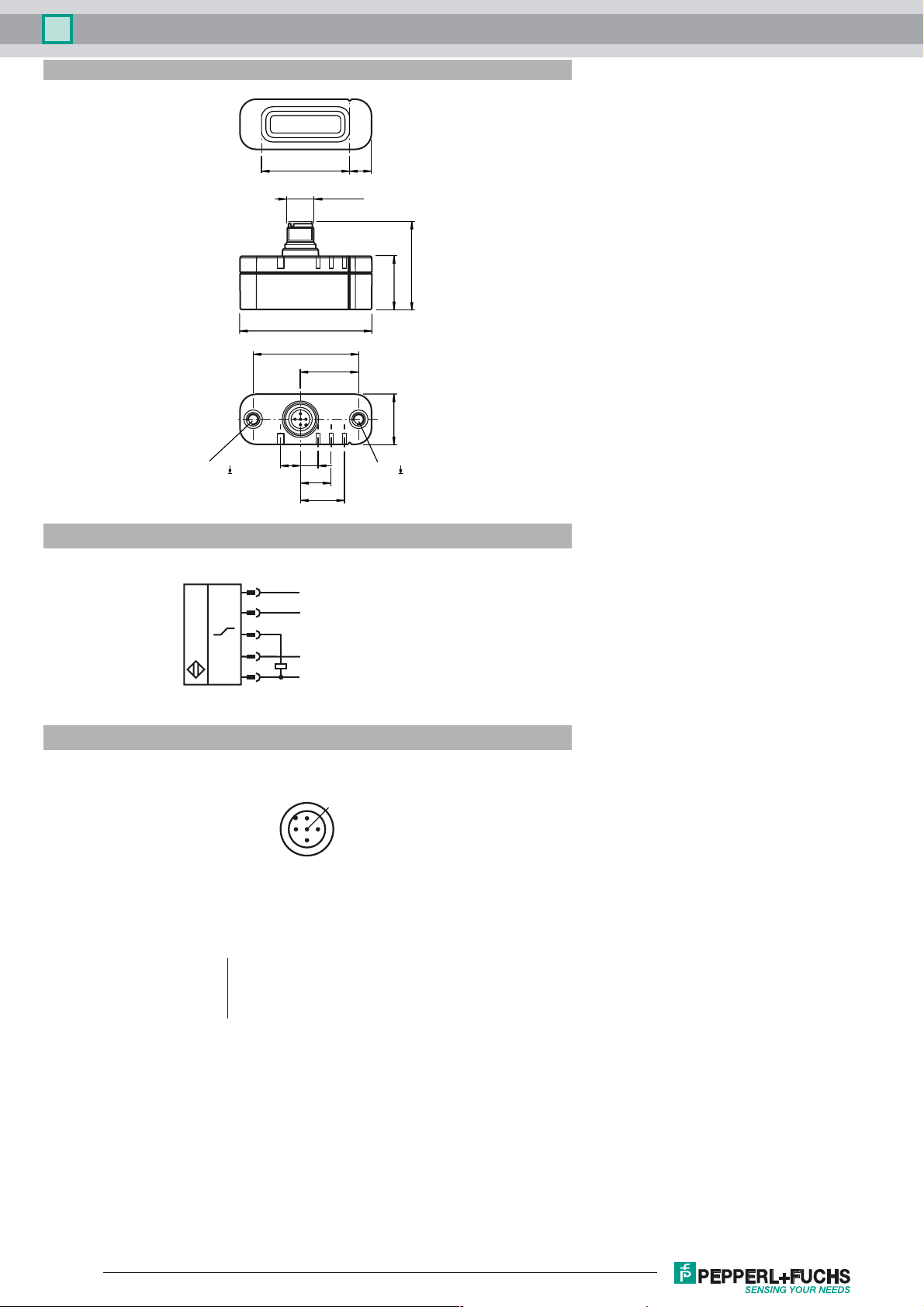
Dimensions
40 10
M12 x 1
40
24.5 ± 0.2
60.3 ± 0.2
48
26.5
23 ± 0.2
M5, 6 M5, 6
9 8
14
20
Electrical Connection
Pinout
Wire colors in accordance with EN 60947-5-2
1 BN
2 WH
3 BU
4 BK
5 GY
1
4
5
2
3
2
L+
C/Q
Analog
n.c.
L-
1
3
(brown)
(white)
(blue)
(black)
(gray)
5
4
Release date: 2018-01-18 13:37 Date of issue: 2018-01-18 315189_eng.xml
Refer to “General Notes Relating to Pepperl+Fuchs Product Information”.
2
Pepperl+Fuchs Group
 Loading...