

Pepperl Fuchs PMI360DV-F130-IU-V15 Instruction manual
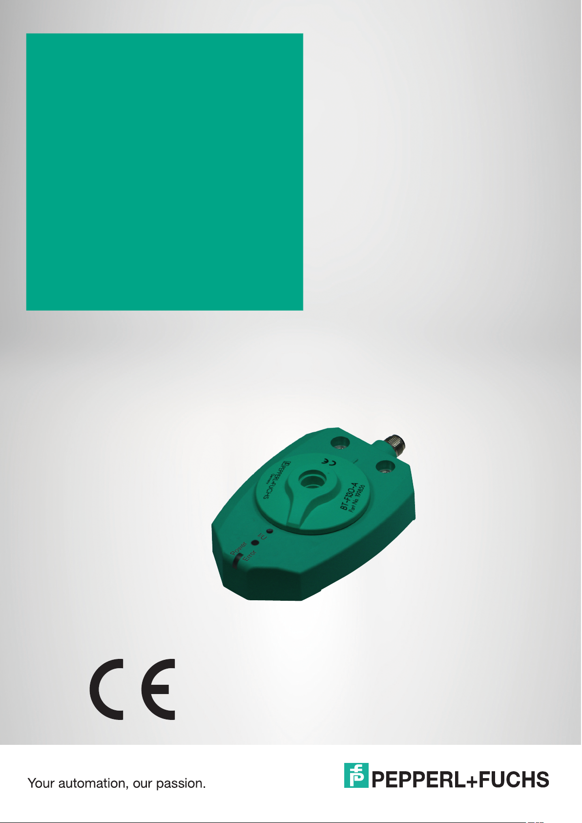
PMI360DV-F130-IU-V15
Inductive angle positioning
system
Manual

With regard to the supply of products, the current issue of the following document is applicable: The
General Terms of Delivery for Products and Services of the Electrical Industry, published by the Central
Association of the Electrical Industry (Zentralverband Elektrotechnik und Elektroindustrie (ZVEI) e.V.)
in its most recent version as well as the supplementary clause: "Expanded reservation of proprietorship"
Worldwide
Pepperl+Fuchs Group
Lilienthalstr. 200
68307 Mannheim
Germany
Phone: +49 621 776 - 0
E-mail: info@de.pepperl-fuchs.com
North American Headquarters
Pepperl+Fuchs Inc.
1600 Enterprise Parkway
Twinsburg, Ohio 44087
USA
Phone: +1 330 425-3555
E-mail: sales@us.pepperl-fuchs.com
Asia Headquarters
Pepperl+Fuchs Pte. Ltd.
P+F Building
18 Ayer Rajah Crescent
Singapore 139942
Phone: +65 6779-9091
E-mail: sales@sg.pepperl-fuchs.com
https://www.pepperl-fuchs.com

PMI360DV-F130-IU-V15
Contents
1 Introduction................................................................................................................ 4
2 Declaration of Conformity......................................................................................... 5
3 Safety .......................................................................................................................... 6
3.1 Symbols Used ................................................................................................ 6
3.2 Intended use .................................................................................................. 6
3.3 General safety instructions .......................................................................... 6
4 Product Description .................................................................................................. 7
4.1 Use and Applications .................................................................................... 7
4.2 Displays and controls.................................................................................... 8
4.3 Delivery package ........................................................................................... 8
4.4 Accessories.................................................................................................... 8
4.4.1 Connection Cables ................................................................................... 9
4.4.2 Actuator............................................................................................. 9
5 Installation................................................................................................................10
5.1 Note on safety .............................................................................................. 10
5.2 Mounting....................................................................................................... 10
5.3 Electrical connection................................................................................... 12
6 Commissioning........................................................................................................ 13
6.1 Programming the analog output ................................................................ 13
7 Output function in normal operation ..................................................................... 15
7.1 Function of the Analog Output I/U ............................................................. 16
8 Maintenance and Repair ......................................................................................... 18
8.1 Maintenance.................................................................................................18
8.2 Resetting the output functions to default.................................................. 18
9 Troubleshooting.......................................................................................................19
9.1 Faults when programming the output ....................................................... 19
9.2 Faults during operation............................................................................... 20
10 Disposal.................................................................................................................... 21
2020-01
3

PMI360DV-F130-IU-V15
Introduction
1 Introduction
Congratulations
You have chosen a device manufactured by Pepperl+Fuchs. Pepperl+Fuchs develops, produces and distributes electronic sensors and interface modules for the market of automation
technology on a worldwide scale.
Symbols used
The following symbols are used in this manual:
Note
This symbol draws your attention to important information.
Handling instructions
You will find handling instructions beside this symbol
Contact
If you have any questions about the device, its functions, or accessories, please contact us at:
Pepperl+Fuchs Group
Lilienthalstraße 200
68307 Mannheim, Germany
Telephone: +49 (0)621 776-1111
Fax: +49 (0)621 776-271111
Email: fa-info@de.pepperl-fuchs.com
2020-01
4

PMI360DV-F130-IU-V15
ISO9001
Declaration of Conformity
2 Declaration of Conformity
This product was developed and manufactured in line with the applicable European standards
and directives.
Note
A declaration of conformity can be requested from the manufacturer.
The product manufacturer, Pepperl+Fuchs Group, 68307 Mannheim, Germany, has a certified
quality assurance system that conforms to ISO 9001.
2020-01
5
PMI360DV-F130-IU-V15
Safety
3 Safety
3.1 Symbols Used
Safety-Relevant Symbols
Danger!
This symbol indicates an imminent danger.
Non-observance will result in personal injury or death.
Warning!
This symbol indicates a possible fault or danger.
Non-observance may cause personal injury or serious property damage.
Caution!
This symbol indicates a possible fault.
Non-observance could interrupt the device and any connected systems and plants, or result in
their complete failure.
Informative Symbols
Note
This symbol brings important information to your attention.
Action
This symbol indicates a paragraph with instructions. You are prompted to perform an action or
a sequence of actions.
3.2 Intended use
The inductive angle positioning system PMI360DV-F130... was designed for position detection
on valve actuators or valves. In addition to these main applications, the inductive angle positioning system PMI360DV-F130... is also suitable for the precision, non-contact detection of all
movement sequences in applications where machine or system components rotate or swivel
around an axis with a maximum diameter of 41.5 mm.
3.3 General safety instructions
Responsibility for planning, assembly, commissioning, operation, maintenance, and dismounting lies with the plant operator.
Installation and commissioning of all devices may be performed only by trained and qualified
personnel.
It is dangerous for the user to carry out modifications and/or repairs and doing so will void the
warranty and exclude the manufacturer from any liability. In the event of any serious errors, stop
using the device. Secure the device against unintended operation. To have the device repaired,
return it to your local Pepperl+Fuchs representative or your sales center.
Note
Disposal
Electronic waste is hazardous. When disposing of the equipment, observe the current statutory
requirements in the respective country of use, as well as local regulations.
2020-01
6
PMI360DV-F130-IU-V15
Product Description
4 Product Description
4.1 Use and Applications
The inductive angular positioning system PMI360DV-F130-IU-V15 is a measuring system
designed for the non-contact detection of the angular position of valve actuators and valves.
The system offers flexible, user-friendly parameterization functions and is suitable for the universal detection and feedback of rotary movements around a fixed rotation point in all areas of
machine and plant construction.
The PMI360DV-F130-IU-V15 has an analog output for the analog indication of angular positions. For high resistance loads (>3.3 k), the angular position is output as a voltage value 0 ...
10 V DC and for low resistance loads (<400 ), as a current value 4 ... 20 mA.
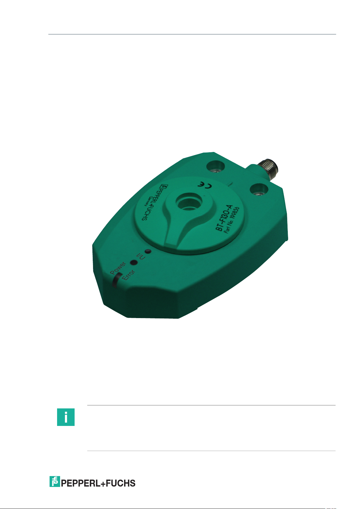
The actuator BT-F130-A (see chapter 4.4) is usually attached to the rotary system component
to detect the position. This actuator rotates in the central hole on the PMI360DV-F130-IU-V15,
contains a metal insert required for position detection and is adapted perfectly to the mechanical requirements of valves or valve actuators.
Note
In principle, the actuator BT-F130-A is not required. A damping element made from
construction steel such as S235JR+AR (previously St37-2) must then be mounted on the rotary
system component. This damping element must fulfill all requirements relating to the material,
dimensions and distances to the inductive angular positioning system PMI360DV-F130... See
chapter 5.2
2020-01
7
 Loading...