

Inductive positioning system PMI210-F110-IU-V1
Technical data
General specifications
Switching element function analog, current or voltage output
Object distance max. 6 mm
Measurement range 0 ... 210 mm
Nominal ratings
Model Number
PMI210-F110-IU-V1
Features
• Analog output 0 V ... 10 V/4 mA ...
20 mA
• Measuring range 0 ... 210 mm
Operating voltage U
Reverse polarity protection reverse polarity protected
Linearity error ± 0.4 mm
Repeat accuracy R ± 0.2 mm
Resolution 210 µm
Temperature drift ± 0.5 mm (-25 °C ... 70 °C)
No-load supply current I
Operating voltage indicator LED green
Functional safety related parameters
MTTFd 310 a
Mission Time (TM) 20 a
Diagnostic Coverage (DC) 0 %
Analog output
Output type 1 current output: 4 ... 20 mA
Load resistor current output: ≤ 400 Ω
Short-circuit protection voltage output: pulsing
Ambient conditions
Ambient temperature -25 ... 70 °C (-13 ... 158 °F)
Mechanical specifications
Connection type 4-pin, M12 x 1 connector
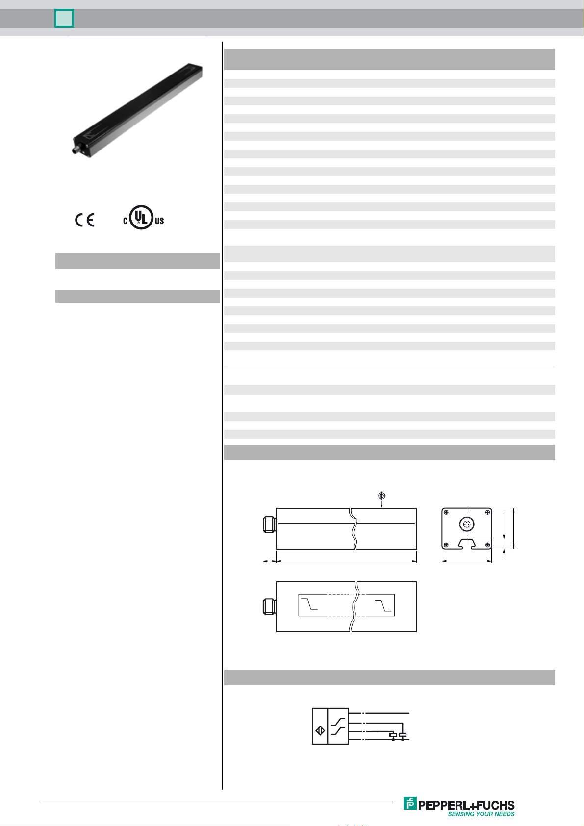
Housing length L 250 mm
Degree of protection IP65
Material
Housing PA 6 / AL
Target mild steel, e. g. 1.0037, SR235JR (formerly St37-2)
Note The data relating to accuracy only apply to a distance to the
Compliance with standards and
directives
Standard conformity
Standards EN 60947-5-2:2007
Approvals and certificates
UL approval cULus Listed, General Purpose, Class 2 Power Source
CCC approval CCC approval / marking not required for products rated ≤36 V
B
0
18 ... 30 V DC
≤ 40 mA
1 voltage output: 0 ... 10 V
voltage output: ≥ 1000 Ω
object to be detected of 1 ... 6 mm.
IEC 60947-5-2:2007
Dimensions
0V/4mA
Electrical Connection
IU
I
Core colours in accordance with
EN 60947-5-2.
30.5
8 ± 0.15
L17
10V/20mA
1
(BN)
4
(BK)
I
2
(WH)
U
3
(BU)
+ UB
4 - 20 mA
0 - 10 V
- UB
41 ± 0.15
Release date: 2012-05-14 13:27 Date of issue: 2016-05-03 191142_eng.xml
Refer to “General Notes Relating to Pepperl+Fuchs Product Information”.
1
Inductive positioning system PMI210-F110-IU-V1
j
Pinout
1
5
2
Wire colors in accordance with EN 60947-5-2
1 BN
2 WH
3 BU
4 BK
(brown)
(white)
(blue)
(black)
4
3
Accessories
BT-F110-G
Damping element for F110 housing sensors; front screw holes
BT-F110-W
Damping element for F110 housing sensors; lateral screw holes
V1-G-2M-PVC
Female cordset, M12, 4-pin, PVC cable
MH-F110
Mounting bracket for mounting F110 series sensors
Instruction manual
• Security advice
Warn ing
• Sensor Properties
The inductive positioning system F110 provides both, a current and voltage signal at the outputs, which is
proportional to the position of the attenuating element.
Output signals: 4 mA ... 20 mA and 0 V ... 10 V
• Attenuating element
The inductive position encoding system F110 is optimally
adjusted to the geometry of the attenuating elements we offer
(see accessories, below).
Note
This product must not be used in applications, where safety of persons
depend on the correct device function.
This product is not a safety device according to EC machinery directive.
13
≥ 41
When using your own attenuating elements, you
must ensure that the active surface of the attenuating element has a width of exactly 13 mm and
overlaps the entire sensor width (41 mm).
A different width has a direct impact on the achievable resolution and accuracy of the system.
≥ 4
Spacing between sensor and attenuating element is from 0 ... 6 mm.
Sensing accuracy is guaranteed between 1 ... 6 mm..
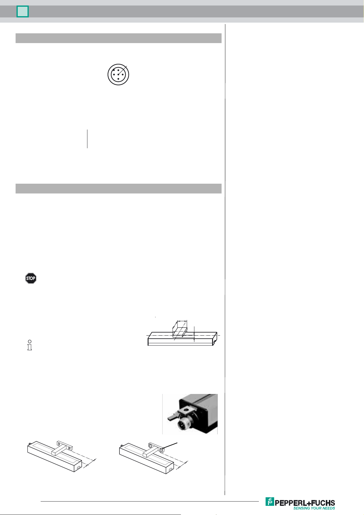
• Installation and operation
Notes on installation
- A flush installation is possible.
- Fixation and installation of the positioning system F110 is carried out by
the use of t-slides. This provides a flexible adaptation to the field situation.
- The distance between the measuring field (bordered area at the front of
the sensor) and the fixing base or fixing element of the attenuating element must at least be 6 mm.
screw head
6
• Notes on operation
The sensor accuracy can be guaranteed, when the spacing between attenuating element and sensor is
within an interval of 1 ... 6 mm.
Refer to “General Notes Relating to Pepperl+Fuchs Product Information”.
6
2
Release date: 2012-05-14 13:27 Date of issue: 2016-05-03 191142_eng.xml

Inductive positioning system PMI210-F110-IU-V1
When the attenuating element leaves the measurement range (figures below):
- the last valid value is maintained at the voltage output until the attenuating element re-enters the valid range.
- the last valid value is maintained at the current output for 0.5 seconds. Afterwards, the output changes to a fault current of 3.6 mA until the attenuating element
re-enters the valid range.
• Definition of measuring range / of measured position
The measured attenuating elements (actuators) position refers to half its width (middle of the actuator). The measuring range starts and ends when the attenuating
element overlaps the labeled measuring area on the sensor at transversal motion (see left figure above).
start of measuring range measured position end of measuring range
w/2
width w of actuator
labeled measuring area
actuator
motion direction of actuator
• Accessories
Attenuating elements Mounting brackets
BT-F110-G BT-F110-W MH-F110
Straight cables: V1-G-2M-PVC (4 wire)
Angled cables: V1-W-2M-PVC (4 wire)
Release date: 2012-05-14 13:27 Date of issue: 2016-05-03 191142_eng.xml
Refer to “General Notes Relating to Pepperl+Fuchs Product Information”.
3
 Loading...