

Inductive positioning system PMI14V-F112-U-V3
Technical data
General specifications
Switching element function Analog voltage output
Installation flush
Object distance max. 2.5 mm
Measurement range 0 ... 14 mm
Nominal ratings
Model Number
PMI14V-F112-U-V3
Features
•Analog output 0...10V
• Scaleable measurement range,
programmable via key
• Measuring range 0 ... 14 mm
Operating voltage U
Reverse polarity protection reverse polarity protected
Linearity error ± 0.3 mm
Repeat accuracy R ± 0.05 mm
Resolution 33 µm
Temperature drift ± 0.4 mm
No-load supply current I
Operating voltage indicator LED
Functional safety related parameters
MTTFd 490 a
Mission Time (T
Diagnostic Coverage (DC) 0 %
Analog output
Output type 1 voltage output: 0 ... 10 V
Load resistor ≥ 2000 Ω
Short-circuit protection limited to 6 mA
Ambient conditions
Ambient temperature -25 ... 70 °C (-13 ... 158 °F)
Mechanical specifications
Connection type M8 x 1 connector, 3-pin
Housing material diecast zinc, not laquered or coated
Degree of protection IP67
Material
Target mild steel, e. g. 1.0037, SR235JR (formerly St37-2)
Note The data relating to accuracy only apply to a distance to the
Compliance with standards and
directives
Standard conformity
Standards EN 60947-5-2:2007
Approvals and certificates
UL approval cULus Listed, Class 2 Power Source, Type 1 enclosure
CCC approval CCC approval / marking not required for products rated ≤36 V
B
0
) 20 a
M
18 ... 30 V DC
≤ 20 mA
object to be detected of 1 ... 2.5 mm.
EN 60947-5-2/A1:2012
IEC 60947-5-2:2007
IEC 60947-5-2 AMD 1:2012
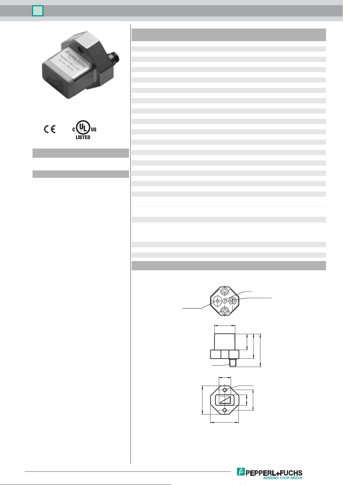
Dimensions
Countersunk
button
LED
V3 connector
25
20
30.5
41
M8 x 1
14
2 x ø 4.3
0V
35
10V
35
25
15
Release date: 2017-09-11 09:21 Date of issue: 2017-09-11 263762_eng.xml
Refer to “General Notes Relating to Pepperl+Fuchs Product Information”.
1
Inductive positioning system PMI14V-F112-U-V3
Electrical Connection
Pinout
Wire colors in accordance with EN 60947-5-2
1 BN
3 BU
4 BK
1
4
3
L+
L-
4
13
(brown)
(blue)
(black)
Additional Information
≥ 18
8
≥ 4
≥ 10
Accessories
BT-F90-W
Damping element for sensors of type F90, F112, and F166; side hole
V3-WM-2M-PUR
Cable socket, M8, 3-pin, PUR cable
Information on Installation and Operation
Safety Information
This product must not be used in applications in which the safety of persons
depends on the function of the device.
Warn un g
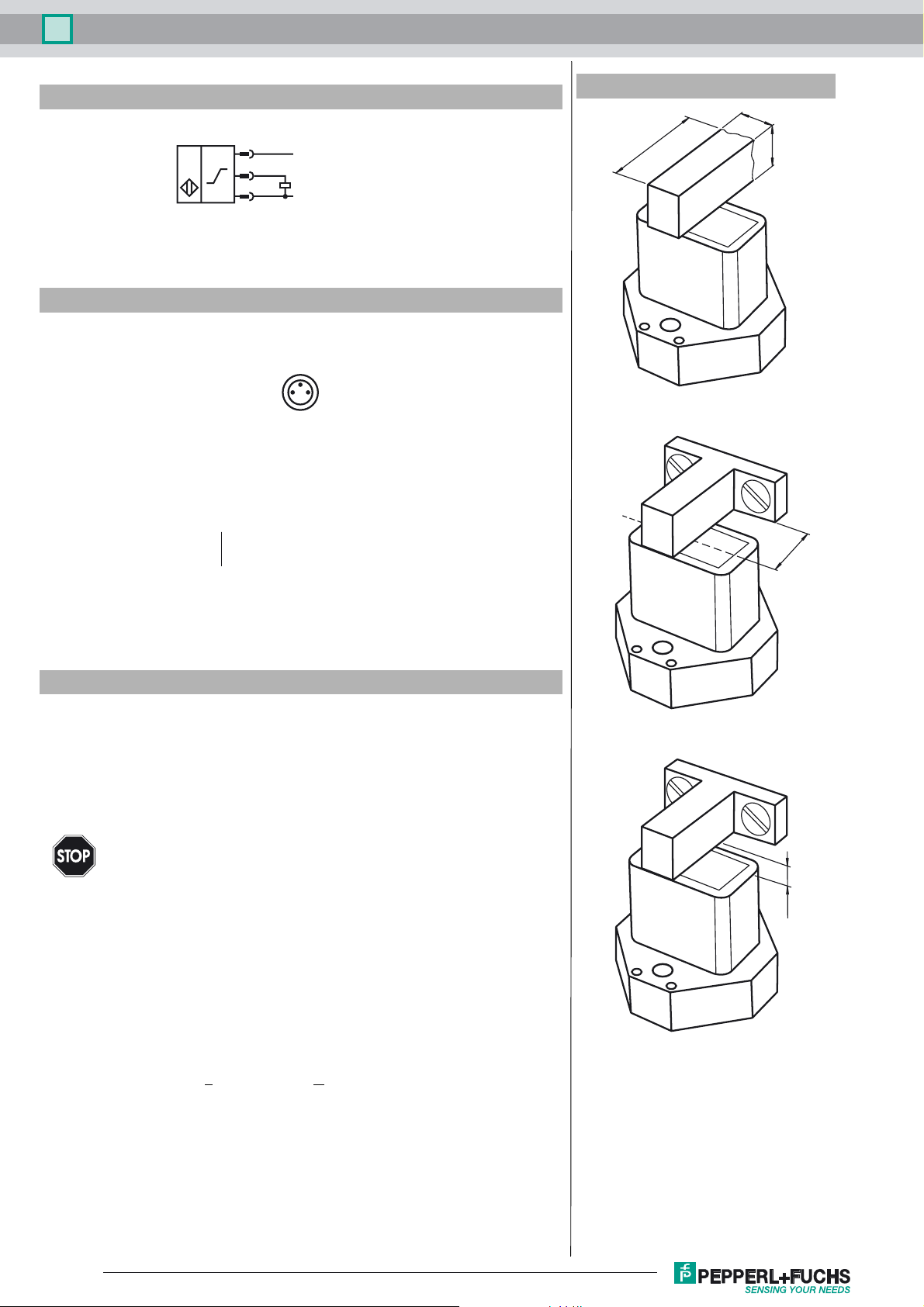
Actuator
The linear position measurement system is optimally aligned to the geometry of Pepperl+Fuchs actuators.
Using Your Own Actuators
Generally speaking, it is possible for you to use your own actuators. The specified measurement accuracy of the sensor will be achieved only if the actuator has the following properties:
• Material: construction steel such as S235JR+AR (previously St37)
• Dimensions (L x W x H): >
• The active surface of the actuator must protrude across the entire sensor width.
Note:
The width of the actuator must be precisely 8 mm. If the width of the actuator deviates from
this value, the position values will differ.
This product is not a safety component as specified in the EU Machinery Directive.
18 mm x 8 mm x > 4 mm
≤ 2.5
Installation
• It is possible to flush mount the device.
• The distance between the center of the measurement field (framed area on the front
Refer to “General Notes Relating to Pepperl+Fuchs Product Information”.
2
Release date: 2017-09-11 09:21 Date of issue: 2017-09-11 263762_eng.xml

Inductive positioning system PMI14V-F112-U-V3
panel of the sensor) and the fixing base or fixing elements (e.g., protruding screw heads) of the actuator must be at least 10 mm.
Operating Instructions
The specified measurement accuracy is achieved if the distance of the actuator from the sensor surface is max. 2.5 mm.
Definition of the Measuring Range/Measured Position
The measured position of the actuator is based on half of the width (center of the actuator).
The measuring range starts and ends when the actuator covers the measurement field marked on the sensor with half of its width in the
course of its longitudinal movement.
start of measuring range measured position end of measuring range
w/2
width w of actuator
labeled measuring area
actuator
motion direction of actuator
Release date: 2017-09-11 09:21 Date of issue: 2017-09-11 263762_eng.xml
Refer to “General Notes Relating to Pepperl+Fuchs Product Information”.
3
 Loading...