

Pepperl Fuchs PMI14V-F112-U-IO-V31 Data Sheet
Inductive positioning system PMI14V-F112-U-IO-V31
Technical data
General specifications
Switching element function Analog voltage output
Installation flush
Object distance max. 2.5 mm
Measurement range 0 ... 14 mm
Nominal ratings
Model Number
PMI14V-F112-U-IO-V31
Features
• Parameterization and diagnosis
via IO-Link
•Analog output 0...10V
• Measuring range 0 ... 14 mm
Operating voltage U
Reverse polarity protection reverse polarity protected
Linearity error ± 0.3 mm
Repeat accuracy R ± 0.05 mm
Resolution 33 µm
Temperature drift ± 0.5 mm
No-load supply current I
Operating voltage indicator LED green
Functional safety related parameters
MTTFd 490 a
Mission Time (T
Diagnostic Coverage (DC) 0 %
Interface
Interface type IO-Link
Mode COM 2 (38.4 kBaud)
Value range 0000h ... 7000h
Analog output
Output type voltage output 0 ... 10 V
Load resistor ≥ 2000 Ω
Short-circuit protection limited to 6 mA
Ambient conditions
Ambient temperature -25 ... 70 °C (-13 ... 158 °F)
Mechanical specifications
Connection type M8 x 1 connector, 4-pin
Housing material diecast zinc, not laquered or coated
Degree of protection IP67
Material
Target mild steel, e. g. 1.0037, SR235JR (formerly St37-2)
Note The data relating to accuracy only apply to a distance to the
Compliance with standards and
directives
Standard conformity
Standards EN 60947-5-2:2007
Approvals and certificates
UL approval cULus Listed, Class 2 Power Source, Type 1 enclosure
CCC approval CCC approval / marking not required for products rated ≤36 V
B
0
) 20 a
M
18 ... 30 V DC
≤ 20 mA
object to be detected of 1 ... 2.5 mm.
EN 60947-5-2/A1:2012
IEC 60947-5-2:2007
IEC 60947-5-2 AMD 1:2012
IEC 61131-9:2013
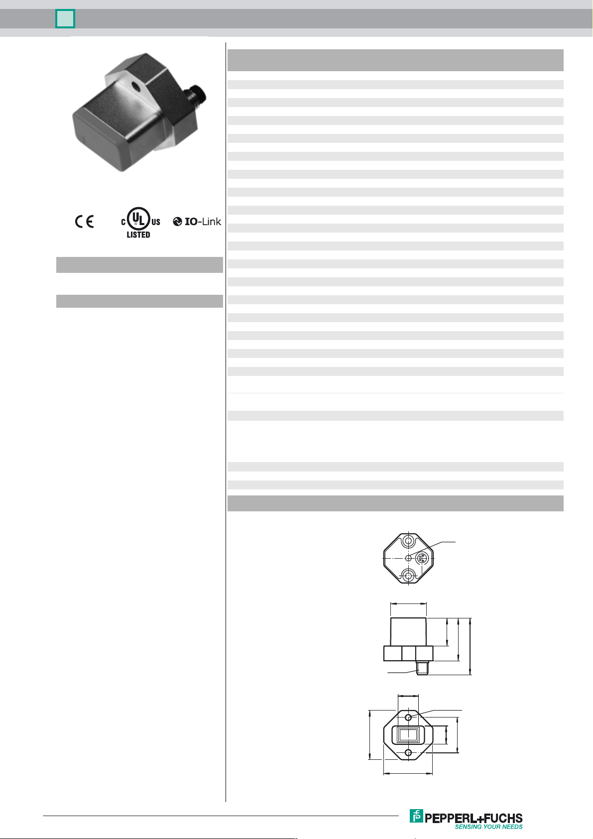
Dimensions
LED
25
20
30.5
41
M8 x 1
14
2 x ø 4.3
35
35
25
15
Release date: 2017-09-11 09:21 Date of issue: 2017-09-11 263760_eng.xml
Refer to “General Notes Relating to Pepperl+Fuchs Product Information”.
1
Inductive positioning system PMI14V-F112-U-IO-V31
Electrical Connection
Pinout
Wire colors in accordance with EN 60947-5-2
1 BN
2 WH
3 BU
4 BK
1
2
4
3
L+
Analog
COM
L-
24
13
(brown)
(white)
(blue)
(black)
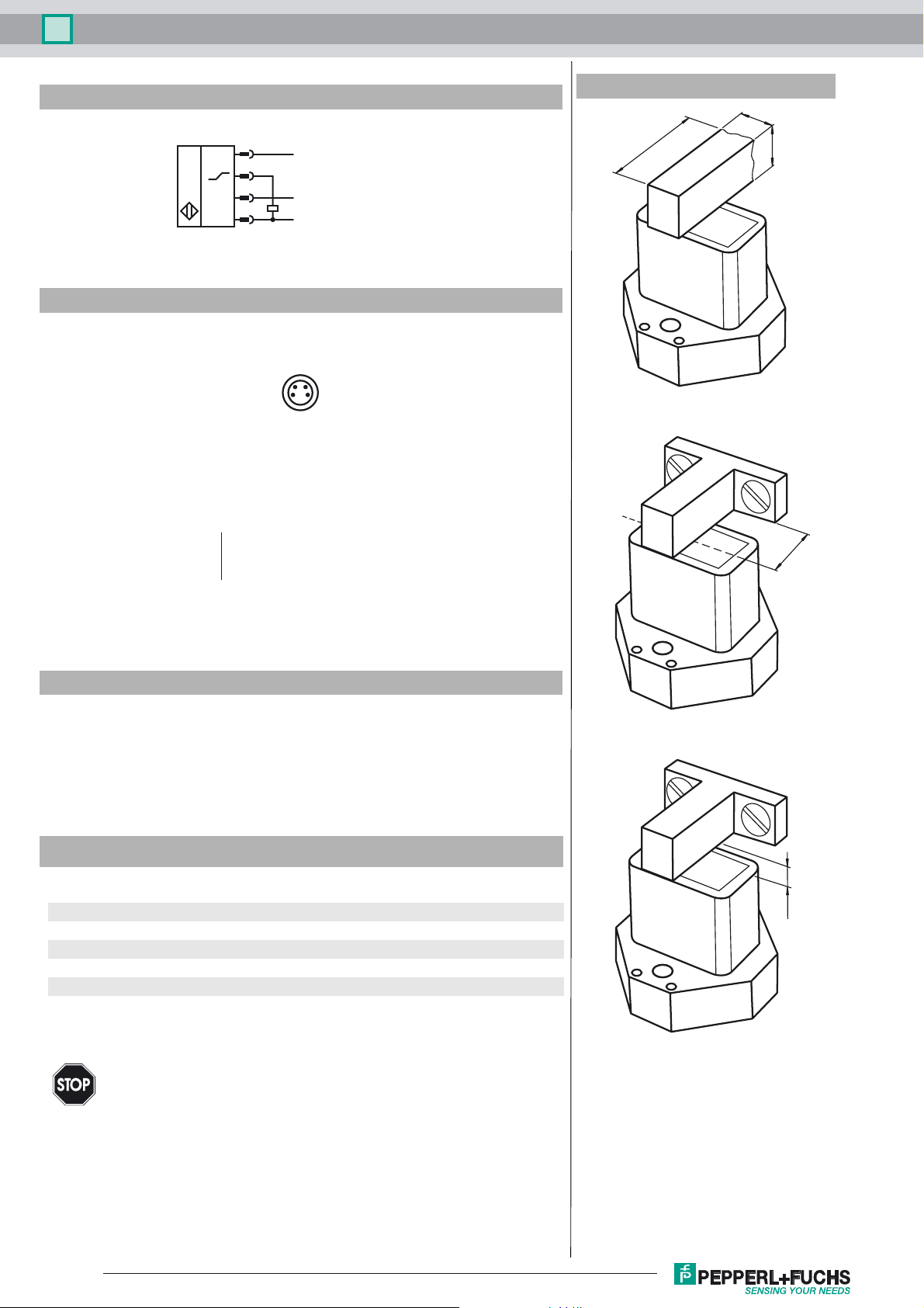
Additional Information
≥ 18
8
≥ 4
≥ 10
Accessories
BT-F90-W
Damping element for sensors of type F90, F112, and F166; side hole
V31-GM-2M-PUR-V1-G
Connection cable, M8 to M12, PUR cable, 4-pin
IO-Link-Master01-USB
IO-Link master, supply via USB port or separate power supply, LED indicators, M12
plug for sensor connection
Description of Sensor Functions
Additional Functions and Parameters (IO-Link)
Additional functions Sensor temperature indicator
Measuring range overrun and underrun indicator
Measuring range Scalable measuring range
Invertible measuring range
Analog output Selectable output type (0 V..10 V; 1 V..5 V)
Information on Installation and Operation
Safety Information
This product must not be used in applications in which the safety of persons
depends on the function of the device.
Warn un g
This product is not a safety component as specified in the EU Machinery Directive.
≤ 2.5
Release date: 2017-09-11 09:21 Date of issue: 2017-09-11 263760_eng.xml
Refer to “General Notes Relating to Pepperl+Fuchs Product Information”.
2
 Loading...