

Inductive positioning system PMI14V-F112-U-IO
Technical data
General specifications
Switching element function Analog voltage output
Installation flush
Object distance max. 2.5 mm
Measurement range 0 ... 14 mm
Nominal ratings
Model Number
PMI14V-F112-U-IO
Features
• Parameterization and diagnosis
via IO-Link
•Analog output 0...10V
• Measuring range 0 ... 14 mm
• Screened lead 2 m
Operating voltage U
Reverse polarity protection reverse polarity protected
Linearity error ± 0.3 mm
Repeat accuracy R ± 0.05 mm
Resolution 33 µm
Temperature drift ± 0.5 mm
No-load supply current I
Operating voltage indicator LED green
Functional safety related parameters
MTTFd 490 a
Mission Time (T
Diagnostic Coverage (DC) 0 %
Interface
Interface type IO-Link
Mode COM 2 (38.4 kBaud)
Value range 0000h ... 7000h
Analog output
Output type voltage output 0 ... 10 V
Load resistor ≥ 2000 Ω
Short-circuit protection limited to 6 mA
Ambient conditions
Ambient temperature -25 ... 70 °C (-13 ... 158 °F)
Mechanical specifications
Connection type 2 m PUR cable , screened
Housing material diecast zinc, not laquered or coated
Degree of protection IP67
Material
Target mild steel, e. g. 1.0037, SR235JR (formerly St37-2)
Note The data relating to accuracy only apply to a distance to the
Compliance with standards and
directives
Standard conformity
Standards EN 60947-5-2:2007
Approvals and certificates
UL approval cULus Listed, Class 2 Power Source, Type 1 enclosure
CCC approval CCC approval / marking not required for products rated ≤36 V
B
0
) 20 a
M
18 ... 30 V DC
≤ 20 mA
object to be detected of 1 ... 2.5 mm.
EN 60947-5-2/A1:2012
IEC 60947-5-2:2007
IEC 60947-5-2 AMD 1:2012
IEC 61131-9:2013
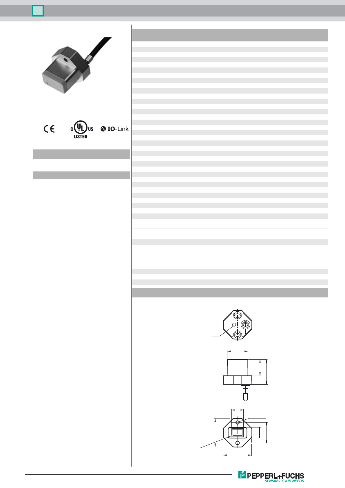
Dimensions
Start
measuring range
LED
35
25
20
30.5
14
2 x ø 4.3
25
15
35
Release date: 2017-09-11 09:21 Date of issue: 2017-09-11 263757_eng.xml
Refer to “General Notes Relating to Pepperl+Fuchs Product Information”.
1
Inductive positioning system PMI14V-F112-U-IO
Electrical Connection
BN
WH
BK
BU
L+
Analog
COM
L-
Accessories
BT-F90-W
Damping element for sensors of type F90, F112, and F166; side hole
V31-GM-2M-PUR-V1-G
Connection cable, M8 to M12, PUR cable, 4-pin
IO-Link-Master01-USB
IO-Link master, supply via USB port or separate power supply, LED indicators, M12
plug for sensor connection
Description of Sensor Functions
Additional Functions and Parameters (IO-Link)
Additional functions Sensor temperature indicator
Measuring range overrun and underrun indicator
Measuring range Scalable measuring range
Invertible measuring range
Analog output Selectable output type (0 V..10 V; 1 V..5 V)
Additional Information
≥ 18
8
≥ 4
≥ 10
Information on Installation and Operation
Safety Information
This product must not be used in applications in which the safety of persons
depends on the function of the device.
Warn un g
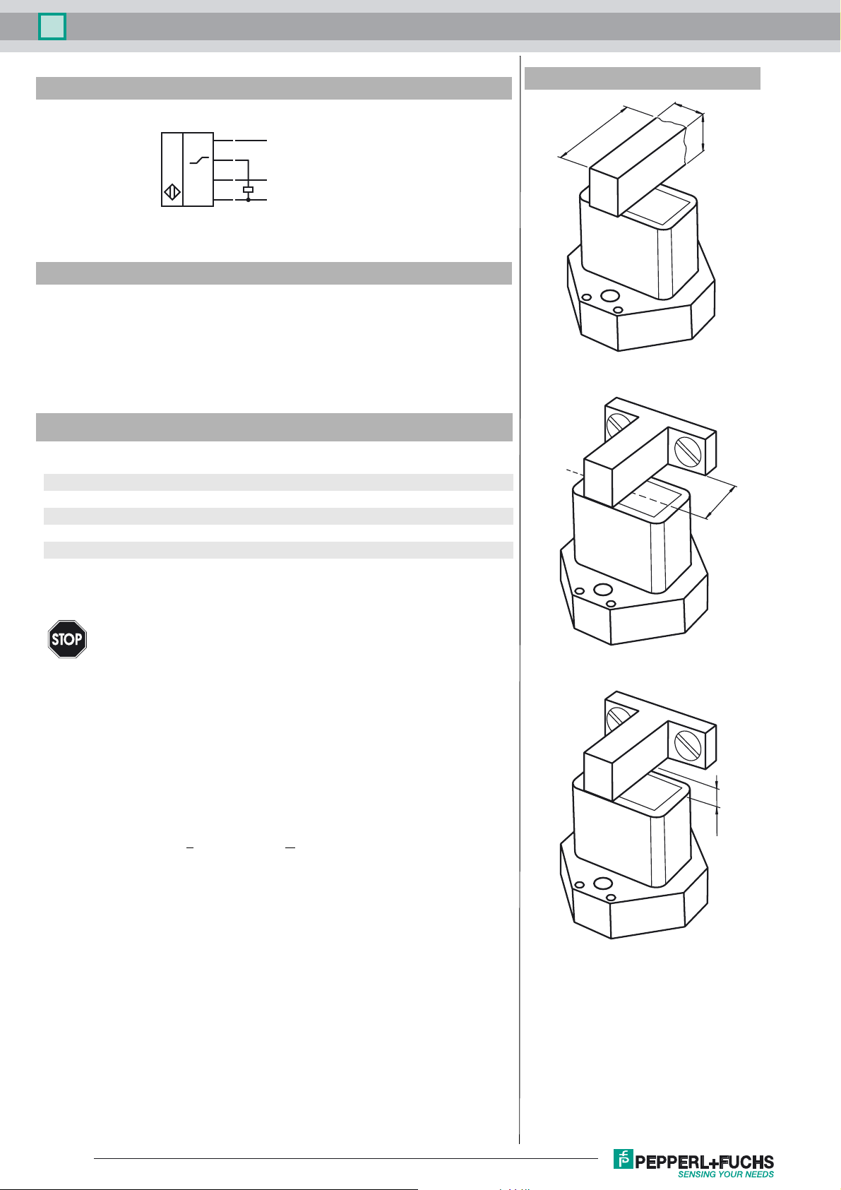
Actuator
The linear position measurement system is optimally aligned to the geometry of Pepperl+Fuchs actuators.
Using Your Own Actuators
Generally speaking, it is possible for you to use your own actuators. The specified measurement accuracy of the sensor will be achieved only if the actuator has the following properties:
• Material: construction steel such as S235JR+AR (previously St37)
• Dimensions (L x W x H): >
• The active surface of the actuator must protrude across the entire sensor width.
Note:
The width of the actuator must be precisely 8 mm. If the width of the actuator deviates from
this value, the position values will differ.
Installation
• It is possible to flush mount the device.
• The distance between the center of the measurement field (framed area on the front
panel of the sensor) and the fixing base or fixing elements (e.g., protruding screw heads)
of the actuator must be at least 10 mm.
Operating Instructions
The specified measurement accuracy is achieved if the distance of the actuator from the
sensor surface is max. 2.5 mm.
This product is not a safety component as specified in the EU Machinery Directive.
18 mm x 8 mm x > 4 mm
≤ 2.5
Definition of the Measuring Range/Measured Position
The measured position of the actuator is based on half of the width (center of the actuator).
Refer to “General Notes Relating to Pepperl+Fuchs Product Information”.
2
Release date: 2017-09-11 09:21 Date of issue: 2017-09-11 263757_eng.xml
 Loading...