

Inductive positioning system PMI120-F90-IU-V1
Technical data
General specifications
Switching element function analog, current or voltage output
Object distance 0.5 ... 3 mm , recommended: 2 mm
Measurement range 0 ... 120 mm
Linearity range 1 ... 119 mm
Nominal ratings
Model Number
PMI120-F90-IU-V1
Features
• Analog output 0 V ... 10 V/4 mA ...
20 mA
• Measuring range 0 ... 120 mm
Operating voltage U
Reverse polarity protection reverse polarity protected
Linearity error within measuring range: ± 0.8 mm
Repeat accuracy ± 0.1 mm
Resolution 125 µm
Temperature drift ± 0.5 mm (-25 °C ... 70 °C)
No-load supply current I
Operating voltage display LED green
Analog output
Output type 1 current output: 4 ... 20 mA
Load resistor current output: ≤ 400 Ω
Short-circuit protection voltage output: pulsing
Ambient conditions
Ambient temperature -25 ... 70 °C (-13 ... 158 °F)
Mechanical specifications
Connection type connector M12 x 1, 4-pin
Protection degree IP67
Material
Housing ABS
Target mild steel, e. g. 1.0037, SR235JR (formerly St37-2)
Compliance with standards and
directives
Standard conformity
Standards EN 60947-5-2:2007
B
0
18 ... 30 V DC
within linearity range: ± 0.4 mm
≤ 40 mA
1 voltage output: 0 ... 10 V
voltage output: ≥ 1000 Ω
IEC 60947-5-2:2007
EN 60947-5-7:2003
IEC 60947-5-7:2003
Approvals and certificates
UL approval cULus Listed, General Purpose, Class 2 Power Source
CCC approval CCC approval / marking not required for products rated
≤36 V
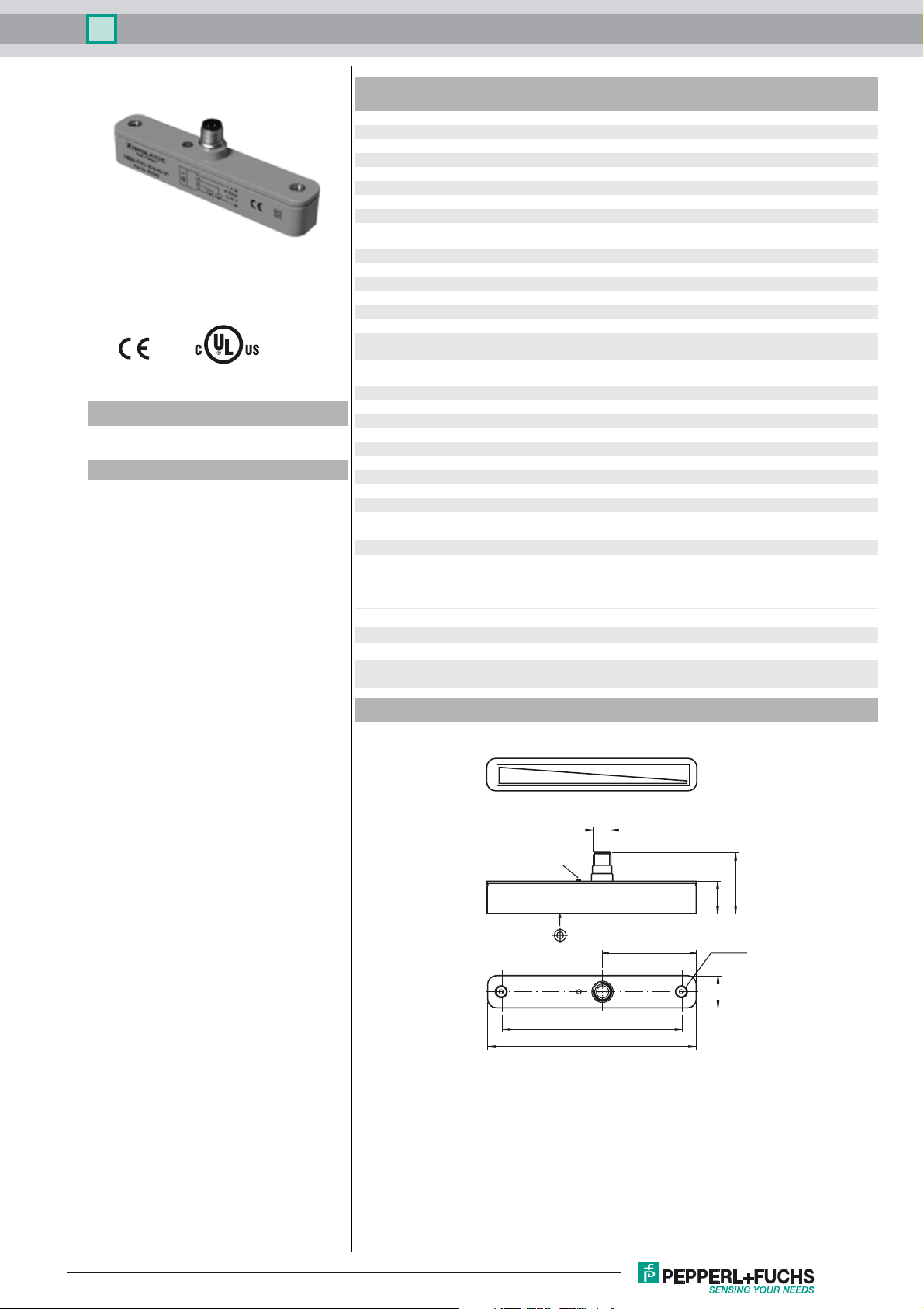
Dimensions
M12 x 1
63
0 V/4 mA
41
22
M5 (2x)
23
10 V/20 mA
LED Power
123
142
Release date: 2013-06-11 15:31 Date of issue: 2013-06-11 191136_eng.xml
Refer to “General Notes Relating to Pepperl+Fuchs Product Information”.
1
Inductive positioning system PMI120-F90-IU-V1
Electrical Connection
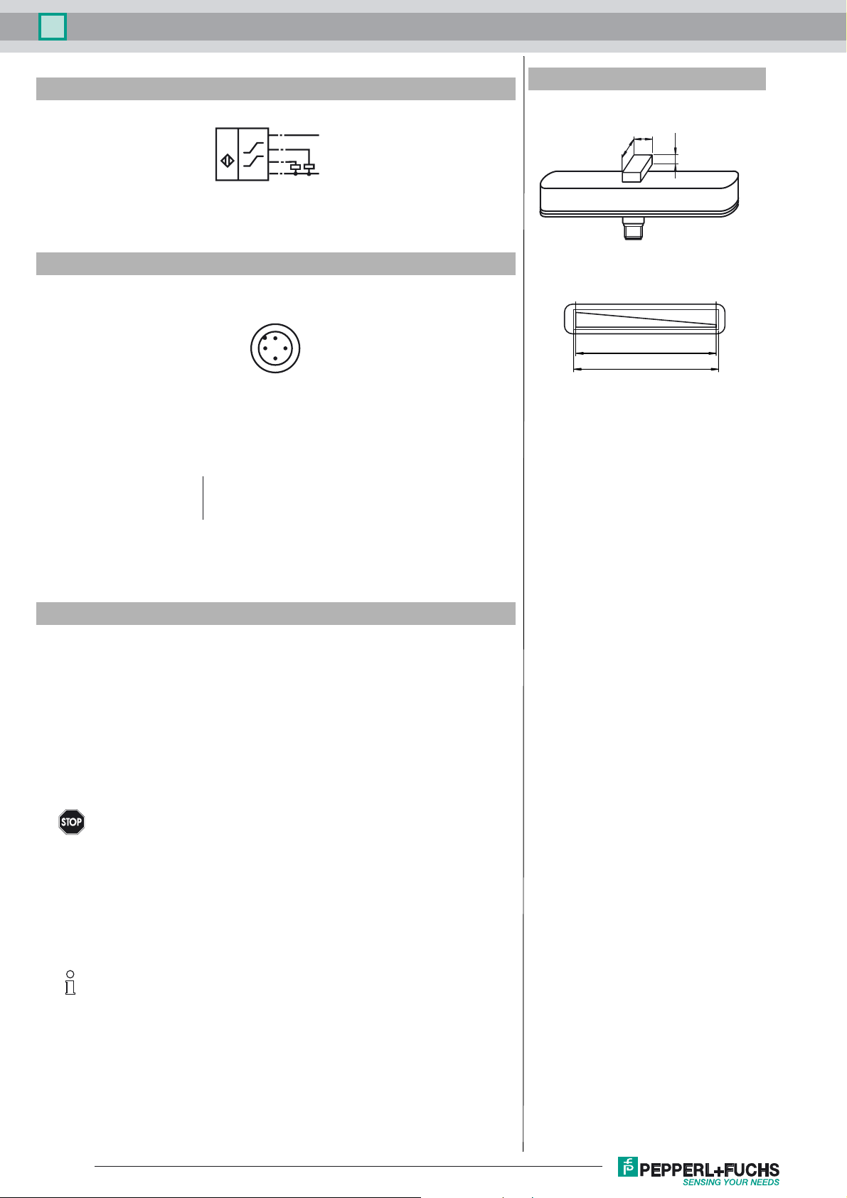
Pinout
Wire colors in accordance with EN 60947-5-2
1 BN
2 WH
3 BU
4 BK
IU
1
(BN)
4
(BK)
I
I
Core colours in accordance with
EN 60947-5-2.
2
U
2
(WH)
3
(BU)
1
3
(brown)
(white)
(blue)
(black)
4-20 mA
4
+ UB
0-10 V
- UB
Additional Information
dimensions for the target object:
8
≥ 18
10 V/20 mA
Linearity range
Measuring range
≥ 4
0 V/4 mA
Accessories
BT-F90-W
Damping element; lateral screw holes
MH-F90
Mounting bracket for mounting of F90 sensors
V1-G-2M-PVC
Female cordset, M12, 4-pin, PVC cable
V1-W-2M-PVC
Female cordset, M12, 4-pin, PVC cable
Operating instructions
• Safety information
Warni ng
• Sensor versions
The F90 linear position measurement system is available in 2 versions.
In the PMI...-F90-IU-V1 version, the position measuring system transmits current and voltage signals proportional to the position of the damping element at the outputs.
The PMI...-F90-IE8-V15 version offers a current signal as well as the option of teaching in two switching
points directly at the sensor independently of one another at the press of a button, which is then indicated
on two switching outputs. Two additional LEDs indicate the output states of the two switching outputs.
Version PMI…-F90-IU-V1
Output signals: 4 mA ... 20 mA and 0 V ... 10 V
Version PMI…-F90-IE8-V15
Output signals: 4 mA ... 20 mA and 2 programmable switching amplifiers
• Programming the PMI…-F90-IE8-V15
The rear of the PMI...-F90-IE8-V15 sensor has two small, slightly recessed push buttons for programming
the switching points. The buttons are marked "teach in" and S1 for switching point S1 and S2 for switching
point S2.
To teach in a switching point, proceed as follows:
- The position detection damping element must be placed at the relevant position, i.e. the switching point
that you wish to teach in.
- Press the corresponding push button for at least two seconds.
The associated switching state LED starts flashing to indicate that the sensor is now in “teach mode”.
This product may not be used in applications where personal safety
depends on the function of the device.
This product is not a safety component as described in EU Machinery Directive.
Only the current output or the voltage output may be used. The unused output must remain
load free.
Note
Refer to “General Notes Relating to Pepperl+Fuchs Product Information”.
2
Release date: 2013-06-11 15:31 Date of issue: 2013-06-11 191136_eng.xml

Inductive positioning system PMI120-F90-IU-V1
- Press the button again to confirm the relevant switching point.
The switching state LED then lights up constantly as long as the damping element is not moved.
The switching point is now taught in and the associated switching point changes to an active state within an actuator adjustment range of ± 1 mm around the taught
switching point.
If the switching point is not confirmed within 80 seconds, the sensor exits “teach mode” and
continues operation with the previous values.
Note
• Damping element
The linear position measurement system is adapted perfectly to the geometry of the damping elements offered in our
product range.
When using other damping elements, always make
sure that the active surface of the damping element
has a width of exactly 8 mm and covers the entire width
Note
of the sensor.
• Installation and operation
Instructions on installation
- Flush installation is possible
- to extend the measuring range, units from the -F90 linear position measurement system can be connected in series (both
behind and adjacent to one another) without a minimum distance.
- The minimum distance between the measuring field (framed area on the sensor front) and mounting base or mounting el-
ements on the damping element must be 3 mm.
Screw head
≥ 18
8
≥ 4
3
• Operating information
The specified measurement accuracy is achieved with an actuator distance of 1 to 3 mm.
If the damping element leaves the measuring area (illustration below):
- the last valid value is retained at the voltage output (PMI…-F90-IU-V1 only) until the damping element enters the valid area again.
- the last valid value is retained for 0.5 seconds at the current output (all types). The output then switches to a fault current of 3.6 mA until the damping element
enters the valid area again.
- the switching amplifiers set to basic state after 0.5 seconds ("normally open").
• Defining the measuring range / measured position
The measured position of the damping element (actuator) is based on half of the width (center of the actuator). The measuring range starts and finishes when half
3
the width of the actuator covers the measurement field marked on the sensor when the actuator makes a longitudinal movement (see left illustration above).
start of measuring range measured position end of measuring range
w/2
width w of actuator
labeled measuring area
actuator
motion direction of actuator
• Accessories
Damping elements Mounting bracket
BT-F90-W MH-F90
Straight cable: V1-G-2M-PVC (4-wire)
Angled cable: V1-W-2M-PVC (4-wire)
Release date: 2013-06-11 15:31 Date of issue: 2013-06-11 191136_eng.xml
Refer to “General Notes Relating to Pepperl+Fuchs Product Information”.
V15-G-2M-PVC (5-wire)
V15-W-2M-PVC (5-wire)
3
 Loading...