

Pepperl Fuchs PMI104-F90-IU-V1 Data Sheet
Inductive positioning system PMI104-F90-IU-V1
Technical data
General specifications
Switching element function analog, current or voltage output
Object distance 0.5 ... 3 mm , recommended: 2 mm
Measurement range 0 ... 104 mm
Linearity range 1 ... 103 mm
Nominal ratings
Model Number
PMI104-F90-IU-V1
Features
• Analog output 0 V ... 10 V/4 mA ...
20 mA
• Measuring range 0 ... 104 mm
Operating voltage U
Reverse polarity protection reverse polarity protected
Linearity error within measuring range: ± 0.8 mm
Repeat accuracy R ± 0.1 mm
Resolution 125 µm
Temperature drift ± 0.5 mm (-25 °C ... 70 °C)
No-load supply current I
Operating voltage indicator LED green
Functional safety related parameters
MTTFd 320 a
Mission Time (T
Diagnostic Coverage (DC) 0 %
Analog output
Output type 1 current output: 4 ... 20 mA
Load resistor current output: ≤ 400 Ω
Short-circuit protection voltage output: pulsing
Ambient conditions
Ambient temperature -25 ... 70 °C (-13 ... 158 °F)
Mechanical specifications
Connection type 4-pin, M12 x 1 connector
Degree of protection IP67
Material
Housing ABS
Target mild steel, e. g. 1.0037, SR235JR (formerly St37-2)
Compliance with standards and
directives
Standard conformity
Standards EN 60947-5-2:2007
Approvals and certificates
EAC conformity TR CU 020/2011
UL approval cULus Listed, General Purpose, Class 2 Power Source
CCC approval CCC approval / marking not required for products rated ≤36 V
B
0
) 20 a
M
18 ... 30 V DC
within linearity range: ± 0.4 mm
≤ 40 mA
1 voltage output: 0 ... 10 V
voltage output: ≥ 1000 Ω
IEC 60947-5-2:2007
EN 60947-5-7:2003
IEC 60947-5-7:2003
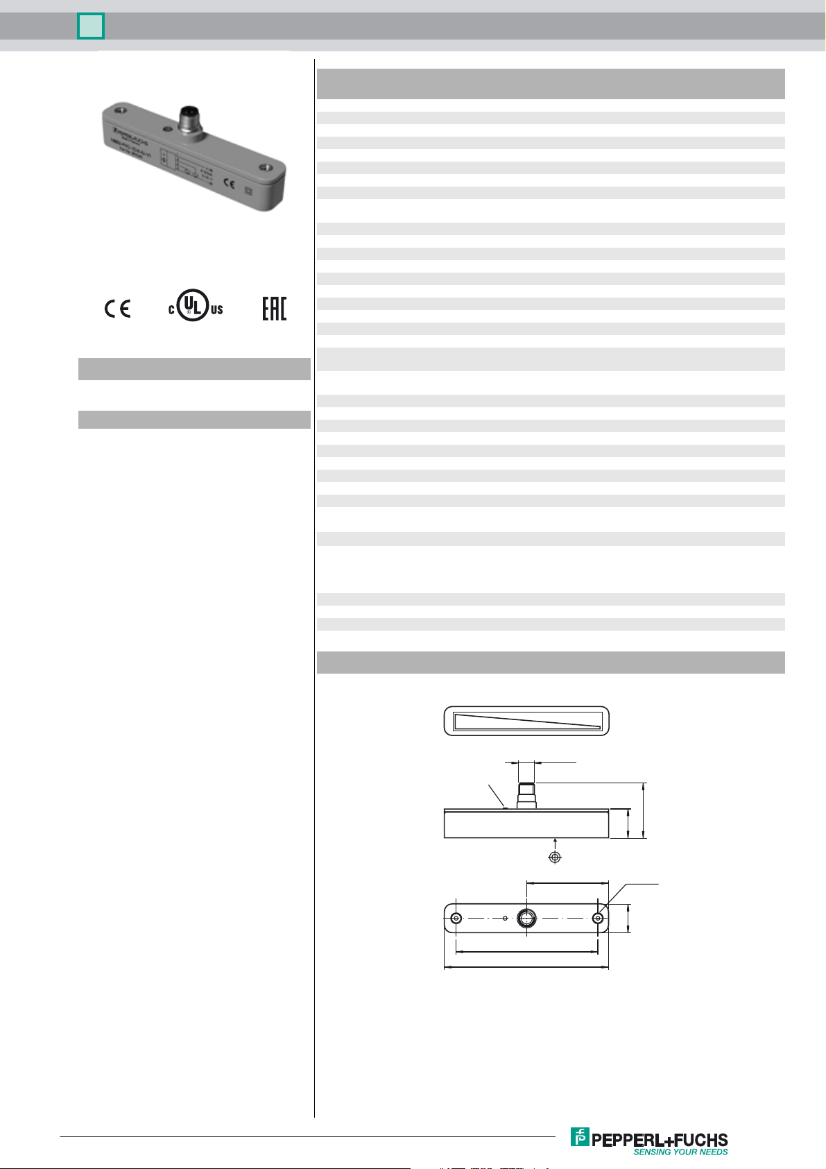
Dimensions
10 V/20 mA
LED
107
126
M12 x 1
63
0 V/4 mA
41
2223
M5 (2x)
Release date: 2017-07-24 09:59 Date of issue: 2017-07-24 191135_eng.xml
Refer to “General Notes Relating to Pepperl+Fuchs Product Information”.
1
Inductive positioning system PMI104-F90-IU-V1
Electrical Connection
IU
I
Core colours in accordance with
EN 60947-5-2.
Pinout
Wire colors in accordance with EN 60947-5-2
1 BN
2 WH
3 BU
4 BK
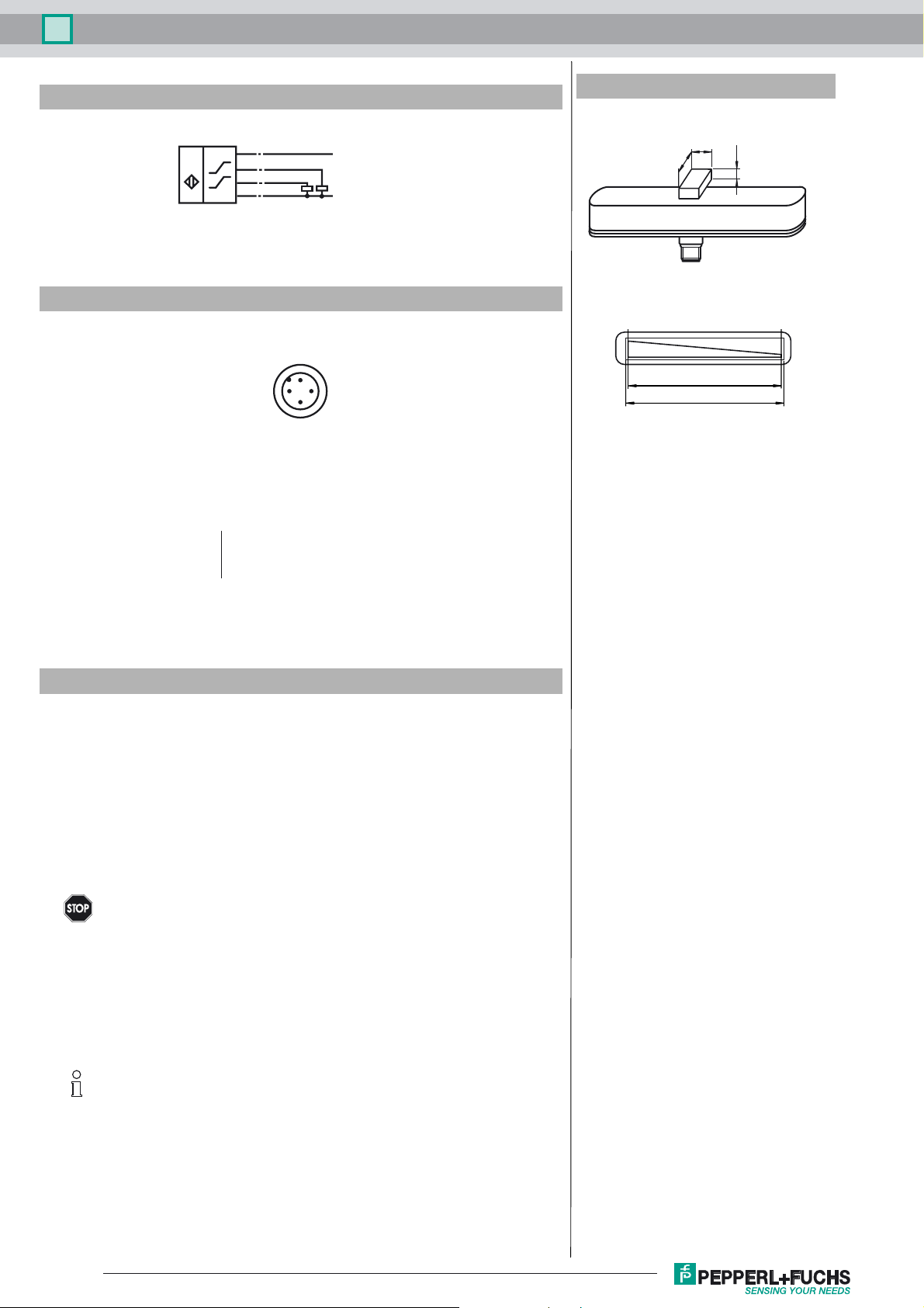
Additional Information
dimensions for the target object:
1
(BN)
4
(BK)
I
2
(WH)
U
3
(BU)
2
(brown)
(white)
(blue)
(black)
+ UB
4 - 20 mA
0 - 10 V
- UB
1
4
3
10 V/20 mA
8
≥ 18
Linearity range
Measuring range
≥ 4
0 V/4 mA
Accessories
BT-F90-W
Damping element for sensors of type F90, F112, and F166; side hole
MH-F90
Mounting bracket for mounting of F90 sensors
V1-G-2M-PVC
Female cordset, M12, 4-pin, PVC cable
BT-F90-G
Damping element for sensors of type F90, F112, and F166; front hole
Operating instructions
• Safety information
Warni ng
• Sensor versions
The F90 linear position measurement system is available in 2 versions.
In the PMI...-F90-IU-V1 version, the position measuring system transmits current and voltage signals proportional to the position of the damping element at the outputs.
The PMI...-F90-IE8-V15 version offers a current signal as well as the option of teaching in two switching
points directly at the sensor independently of one another at the press of a button, which is then indicated
on two switching outputs. Two additional LEDs indicate the output states of the two switching outputs.
Version PMI…-F90-IU-V1
Output signals: 4 mA ... 20 mA and 0 V ... 10 V
Version PMI…-F90-IE8-V15
Output signals: 4 mA ... 20 mA and 2 programmable switching amplifiers
• Programming the PMI…-F90-IE8-V15
The rear of the PMI...-F90-IE8-V15 sensor has two small, slightly recessed push buttons for programming
the switching points. The buttons are marked "teach in" and S1 for switching point S1 and S2 for switching
point S2.
To teach in a switching point, proceed as follows:
- The position detection damping element must be placed at the relevant position, i.e. the switching point
that you wish to teach in.
- Press the corresponding push button for at least two seconds.
This product may not be used in applications where personal safety
depends on the function of the device.
This product is not a safety component as described in EU Machinery Directive.
Only the current output or the voltage output may be used. The unused output must remain
load free.
Note
Refer to “General Notes Relating to Pepperl+Fuchs Product Information”.
2
Release date: 2017-07-24 09:59 Date of issue: 2017-07-24 191135_eng.xml
 Loading...