

Page 1
PGV...-F200/-F200A...-R4-V19
Incident Light Positioning System
MANUAL
Page 2

With regard to the supply of products, the current issue of the following document is ap-
plicable: The General Terms of Delivery for Products and Services of the Electrical Indus-
try, published by the Central Association of the Electrical Industry (Zentralverband
Elektrotechnik und Elektroindustrie (ZVEI) e.V.) in its most recent version as well as the
supplementary clause: "Expanded reservation of proprietorship"
PGV...-F200/-F200A...-R4-V19
Page 3

PGV...-F200/-F200A...-R4-V19
3
1 Safety ........................................................................................... 5
1.1 Introduction .......................................................................................... 5
1.1.1 Content of this Document .................................................................. 5
1.1.2 Manufacturer...................................................................................... 5
1.1.3 Target Group, Personnel .................................................................... 5
1.1.4 Symbols Used.................................................................................... 6
2 Product Description ................................................................... 7
2.1 Use and Application............................................................................. 7
2.2 The RS-485 Interface ........................................................................... 9
2.3 LED Indicators and Controls............................................................... 9
2.4 Accessories ........................................................................................ 11
3 Installation................................................................................. 12
3.1 Mounting the Read Head................................................................... 12
3.2 Mounting the Colored Tape and Code Tape .................................... 14
3.3 Electrical Connection ........................................................................ 30
4 Commissioning......................................................................... 32
4.1 Specifying the First Direction Decision ........................................... 32
4.2 Direction Decision.............................................................................. 32
4.3 Parameter assignment....................................................................... 34
4.3.1 Internal Parameterization Using Parameterization Software ............. 34
4.3.2 External Parameterization Using Code Cards .................................. 35
5 Operation and communication................................................ 37
5.1 Communication via the RS-485 Interface ........................................ 37
5.1.1 Request Telegram............................................................................ 37
5.1.2 Position Response Telegram ........................................................... 38
5.1.3 Direction Decision Request Telegram.............................................. 44
5.1.4 Color Choice Request Telegram ...................................................... 44
5.2 Operation Using Control Codes ....................................................... 46
5.3 Operation Using Repair Tape ............................................................ 47
Page 4

4
PGV...-F200/-F200A...-R4-V19
6 Appendix ................................................................................... 48
6.1 Code Cards for External Parameterization ......................................48
6.1.1 Code Cards with Special Functions.................................................. 48
6.1.2 Code Cards for Setting the Read Head Address ..............................51
6.1.3 Code Cards for Adjusting the Resolution.......................................... 52
6.1.4 Code cards for setting the transfer rate............................................. 53
6.1.5 Code cards for adjusting the terminator............................................ 55
6.1.6 Code Cards for Adjusting Input/Output 3..........................................56
Page 5
PGV...-F200/-F200A...-R4-V19
Safety
2019-03
5
1Safety
1.1 Introduction
1.1.1 Content of this Document
This document contains information required to use the product in the relevant phases of the
product life cycle. This may include information on the following:
Product identification
Delivery, transport, and storage
Mounting and installation
Commissioning and operation
Maintenance and repair
Troubleshooting
Dismounting
Disposal
The documentation comprises the following parts:
This document
Datasheet
In addition, the documentation may comprise the following parts, if applicable:
EU-type examination certificate
EU declaration of conformity
Attestation of conformity
Certificates
Control drawings
Instruction manual
Other documents
1.1.2 Manufacturer
1.1.3 Target Group, Personnel
Responsibility for planning, assembly, commissioning, operation, maintenance, and
dismounting lies with the plant operator.
Only appropriately trained and qualified personnel may carry out mounting, installation,
commissioning, operation, maintenance, and dismounting of the product. The personnel must
have read and understood the instruction manual and the further documentation.
Prior to using the product make yourself familiar with it. Read the document carefully.
Note!
For full information on the product, refer to the further documentation on the Internet at
www.pepperl-fuchs.com.
Pepperl+Fuchs GmbH
Lilienthalstraße 200, 68307 Mannheim, Germany
Internet: www.pepperl-fuchs.com
Page 6
2019-03
6
PGV...-F200/-F200A...-R4-V19
Safety
1.1.4 Symbols Used
This document contains symbols for the identification of warning messages and of informative
messages.
Warning Messages
You will find warning messages, whenever dangers may arise from your actions. It is
mandatory that you observe these warning messages for your personal safety and in order to
avoid property damage.
Depending on the risk level, the warning messages are displayed in descending order as
follows:
Informative Symbols
Action
This symbol indicates a paragraph with instructions. You are prompted to perform an action or
a sequence of actions.
Danger!
This symbol indicates an imminent danger.
Non-observance will result in personal injury or death.
Warning!
This symbol indicates a possible fault or danger.
Non-observance may cause personal injury or serious property damage.
Caution!
This symbol indicates a possible fault.
Non-observance could interrupt the device and any connected systems and plants, or result in
their complete failure.
Note!
This symbol brings important information to your attention.
Page 7
PGV...-F200/-F200A...-R4-V19
Product Description
2019-03
7
2 Product Description
2.1 Use and Application
Intended Use
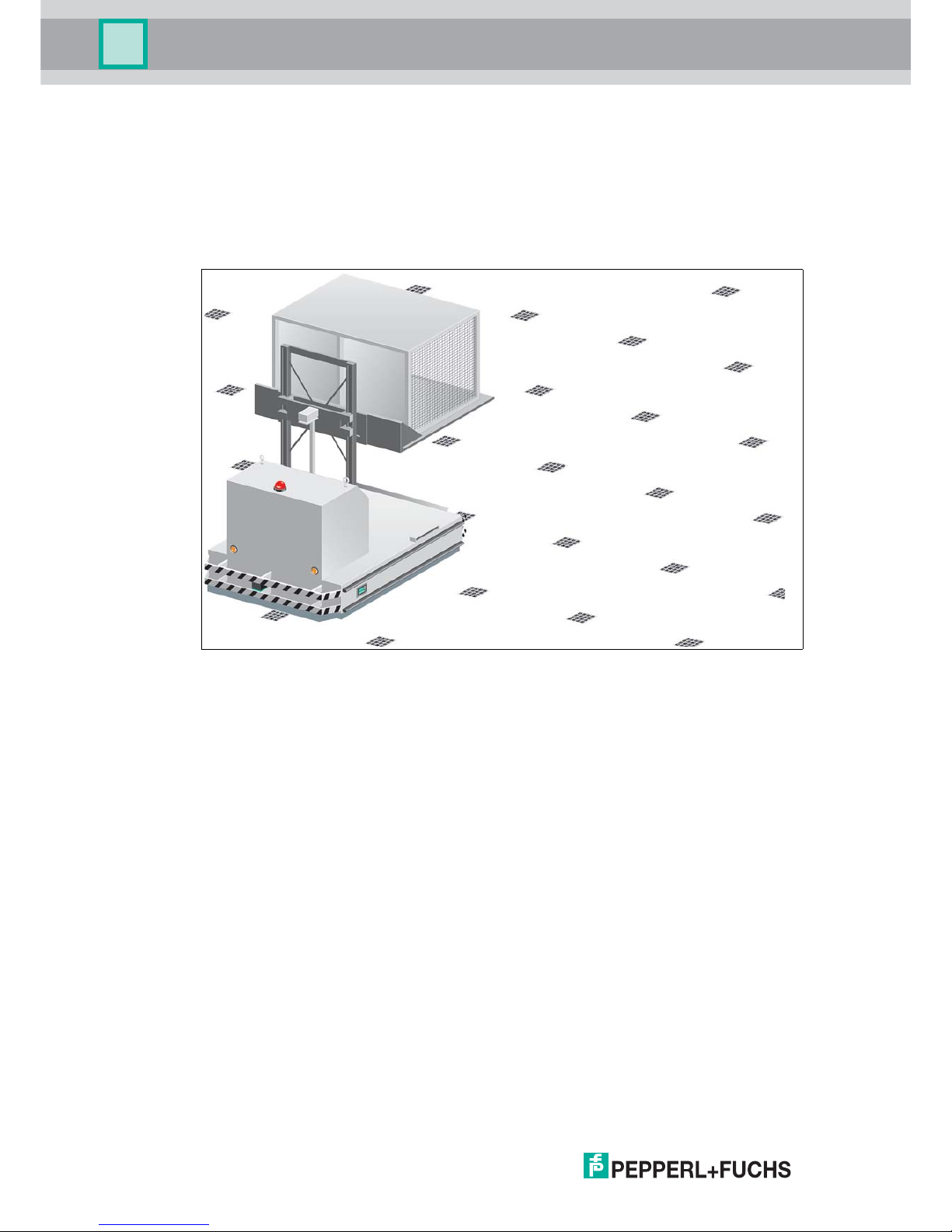
This device, when used together with a colored tape affixed to the floor and code tapes printed
with Data Matrix codes, constitute a high-resolution lane tracking and positioning system. It
can be used in all applications where automated guided vehicles (AGV) are to be positioned
precisely at marked positions along a given lane.
The read head forms part of the positioning system in the Pepperl+Fuchs incident light
process. The read head's features include a camera module and an integrated illumination
unit. The read head uses these features to detect a colored tape stuck to the floor or a painted
color lane to track the lane. The read head detects Data Matrix tags to navigate within a grid.
The read head also detects control codes and position markers in the form of Data Matrix
codes printed on a self-adhesive code tape. Data Matrix code tapes and Data Matrix tags have
priority over colored tapes or colored lanes.
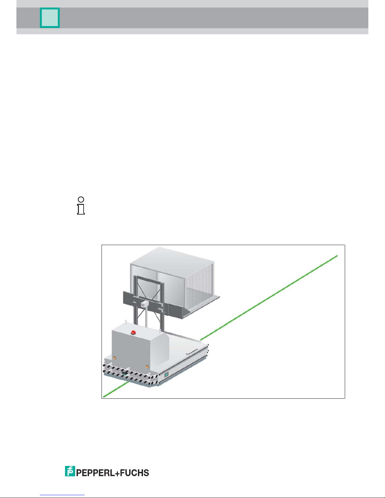
The Data Matrix code tapes are installed in a fixed position instead of or along with the colored
tape. The read head is located on an automated guided vehicle (AGV) and guides this vehicle
along the colored tape.
Figure 2.1 Automated guided vehicle with green colored tape
Note!
Priority
Data Matrix code tapes and Data Matrix tags have priority over colored tapes or colored lanes.
If the read head detects a Data Matrix code tape or Data Matrix tags in the field of view, colored
tapes or colored lanes in the field of view are ignored.
Page 8
2019-03
8
PGV...-F200/-F200A...-R4-V19
Product Description
Tag Mode
In addition to the tracking, you can use the read head in tag mode. The read head detects Data
Matrix tags, which are typically glued onto the floor in a grid. The individual Data Matrix tags
are numbered consecutively and include position information. The read head reports the
position of the AGV in relation to the zero point of the Data Matrix tag to the controller.
The tag mode allows the AGV to move freely in as large a grid as desired, without having to
mark the crossing paths with lane tapes.
Figure 2.2 Automated guided vehicle with Data Matrix tags
The read head switches automatically between tag mode and lane tracking. This allows an
automated guided vehicle to be guided from one Data Matrix tag grid via a colored or Data
Matrix lane to another Data Matrix tag grid.
The extensive yet user-friendly parameterization options as well as the configurable inputs and
outputs mean that the read head can easily be adapted to suit each application.
Page 9
PGV...-F200/-F200A...-R4-V19
Product Description
2019-03
9
2.2 The RS-485 Interface
The read head is equipped with an RS-485 interface for communication purposes, i.e.,
parameterizing the read head functions or reading out current process data during operation.
This interface is operated in 8-E-1 mode and fitted with a terminator that can be activated or
deactivated by parameterizing the sensor head accordingly. The RS-485 interface supports
the following transfer rates:
38400 bit/s
57600 bit/s
76800 bit/s
115200 bit/s(preset value)
230400 bit/s
Data structure of the RS-485 interface
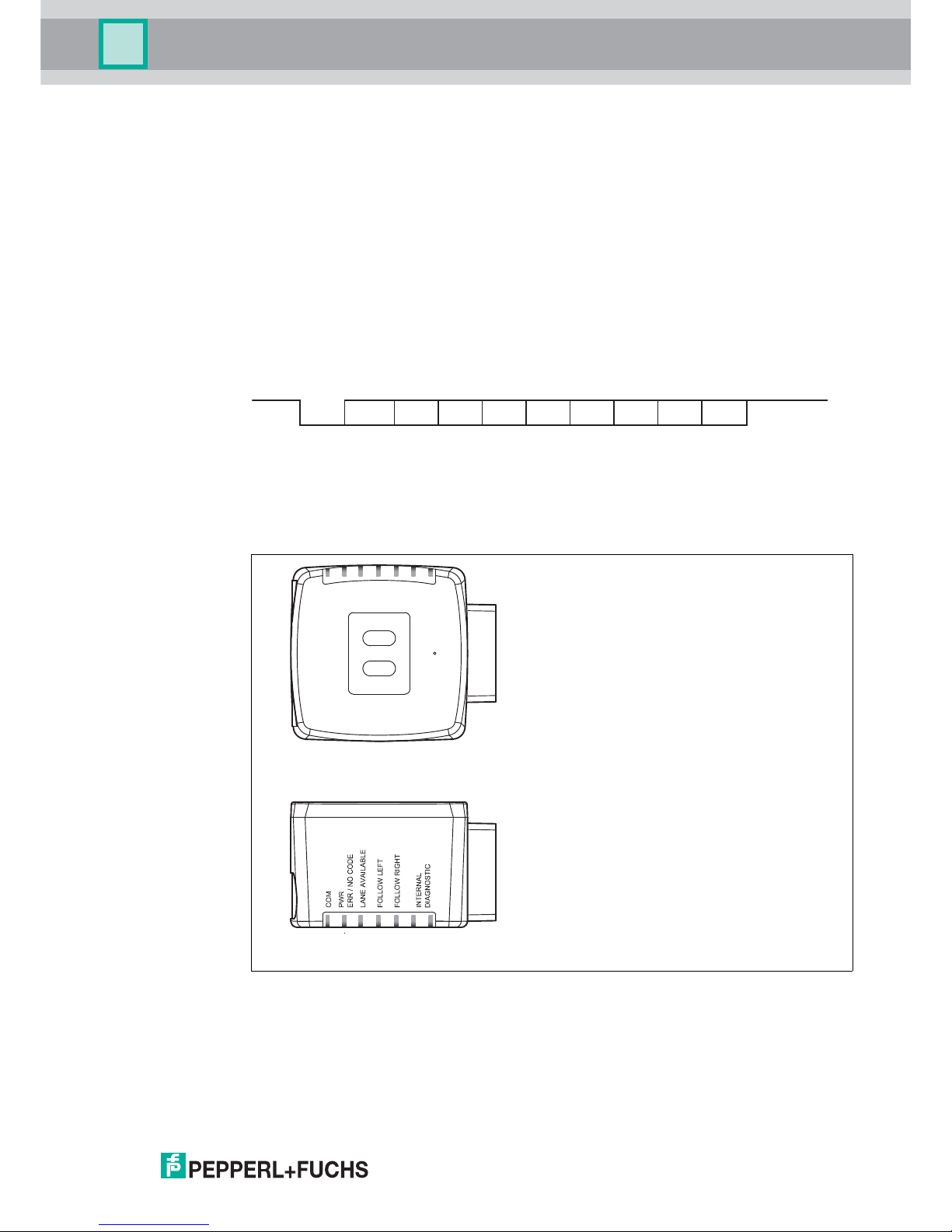
2.3 LED Indicators and Controls
The read head is equipped with seven indicator LEDs for carrying out visual function checks
and rapid diagnostics. The read head is equipped with two buttons at the back for activating
parameterization mode. Button 1 is labeled ADJUST. Button 2 is labeled CONFIG.
Figure 2.3
Bit 0
LSB MSBStart Stop
Bit 1 Bit 2 Bit 3 Bit 4 Bit 5 Bit 6 Bit 7 Parity
ADJUST
CONFIG
1
2
LED 1 2 3 4 5 6 7
Page 10
2019-03
10
PGV...-F200/-F200A...-R4-V19
Product Description
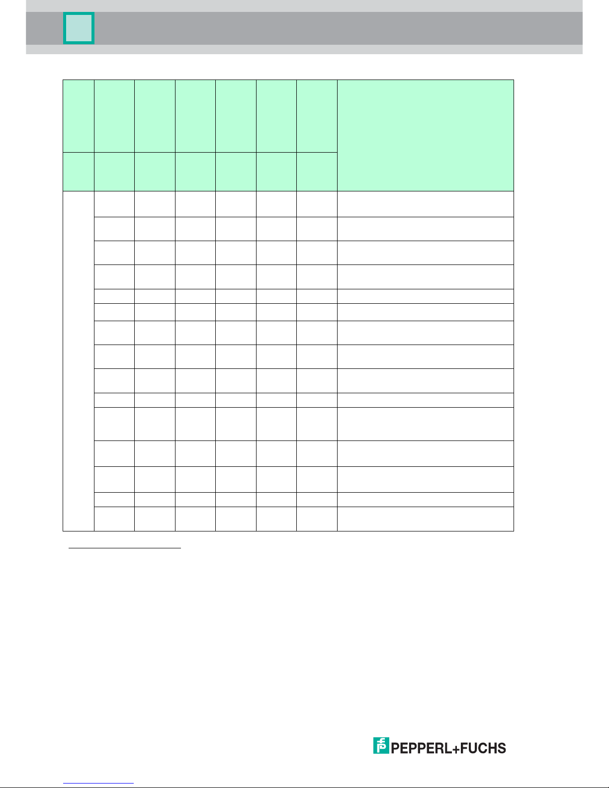
LED
[#1]
COM
[#2]
PWR
ERR/NO
CODE
[#3]
LANE
AVAILA
BLE
[#4]
FOLLO
W LEFT
[#5]
FOLLO
W
RIGHT
[#6] &
[#7]
INTERN
AL
DIAGN
OSTIC
DescriptionColor Yellow
Green/
red
Yellow Yellow Yellow
Red/
green/
yellow
Status
x
1
1.LED status has no meaning
Flashes
red
x x x x Code tape outside read range
f
flash
= 2 Hz
x Lights
up red
x x x x
System errorError Codes40
2
2.No lane selected, for example. .see table "Error Codes" on page 40
x Lights
up green
x x x x Code tape detected, absolute position
available
x x Lights
up
x x x Colored tape detected
x x Off x x x Colored tape outside read range
x x x Off Off x
No direction selection activated4
3
3.See chapter 4
x x x Lights upOff x "Follow left-hand lane" activated
x x x Off Lights
up
x "Follow right-hand lane" activated
x x x Lights upLights
up
x "Straight ahead" activated
Flashes x x x x x RS-485 data transfer
Flashes Flashes
red
Flashes Flashes Flashes Off Normal operation. Indication for 2 secs if a
button is pressed when the time lock is
enabled.
Off Red, 3
sec
Flashes Off Off Off Code card faulty
f
flash
= 2 Hz for 3 sec
Off Green, 1
sec
Flashes Off Off Off Code card detected
f
flash
= 2 Hz for 1 sec
x Off x x x Off Time lock for buttons disabled
x x x x x Lights upInternal error
Return to Pepperl+Fuchs
Table 2.1 LED Status
Page 11
PGV...-F200/-F200A...-R4-V19
Product Description
2019-03
11
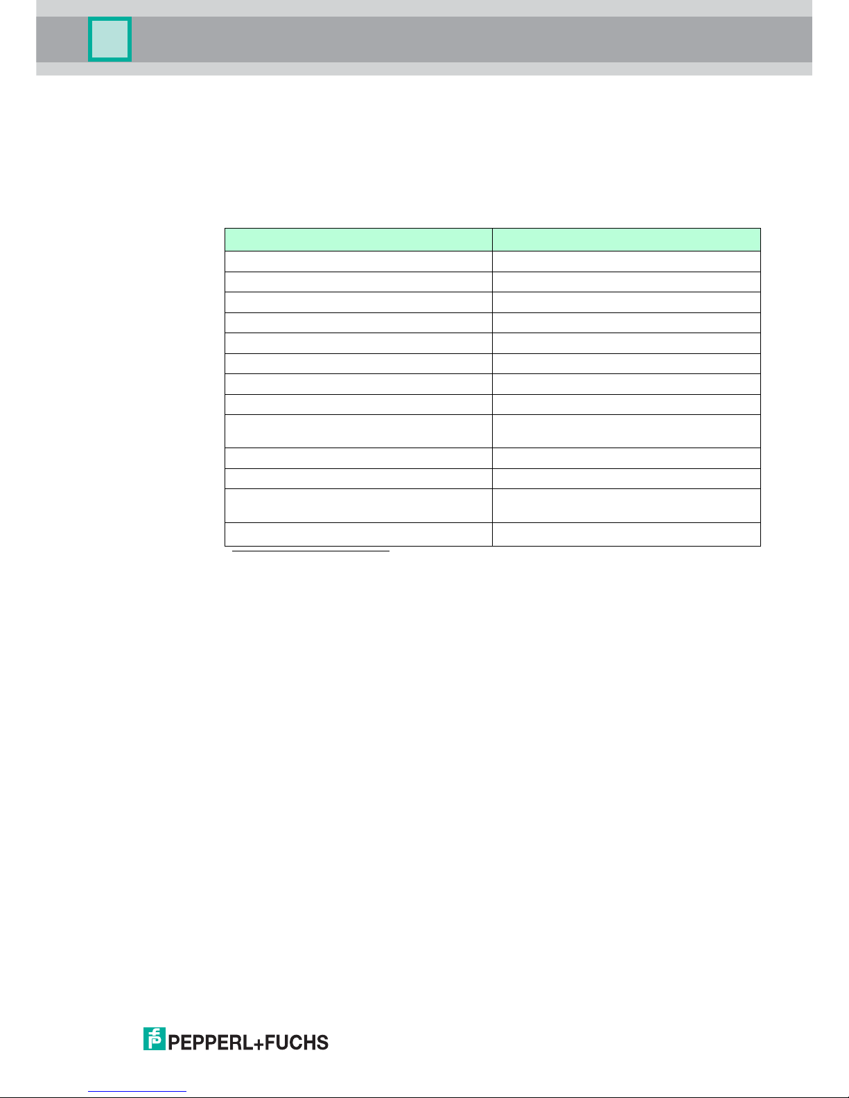
2.4 Accessories
Compatible accessories offer enormous potential for cost savings. Such accessories not only
save you a great deal of time and effort when commissioning for the first time, but also when
replacing and maintaining our products.
If products are used in harsh ambient conditions, appropriate Pepperl+Fuchs accessories can
be used to extend the service life of these products.
Order designation Description
PGV-CC25-0* Data Matrix control codes
PGV*M-CA25-* Data Matrix position tape
PGV-CR25 Repair tape
PGV85-CT4 Data Matrix tag
PGV25M-CD100-CLEAR Protective film for code and colored tape
PGV33M-CB19-BU Colored tape; blue
PGV33M-CB19-GN Colored tape; green
PGV33M-CB19-RD Colored tape; red
PCV-SC12
PCV-SC12A
Grounding clip
V19-G-ABG-PG9-FE Grounding terminal and plug (set)
PCV-USB-RS485 converter set USB/RS-485 interface converter
PCV-KBL-V19-STR-RS485 Cable unit with 24 V power supply and V19
connection cable to RS-485 interface
V19-G-*M-*
Configurable connection cable
1
1.Ask your contact person at Pepperl+Fuchs
Page 12
2019-03
12
PGV...-F200/-F200A...-R4-V19
Installation
3Installation
3.1 Mounting the Read Head
Mount the PGV... read head on the automated guided vehicle using the four screws on the
mounting adapter on the read head. Mount the read head in such a way that the lens with the
ring light and camera module are directed toward the colored tape.
The mounting must be stable enough so that the read head does not leave its depth of focus
range during operation.
The distance between the read head and the floor should be the same as the read distance of
the read head.
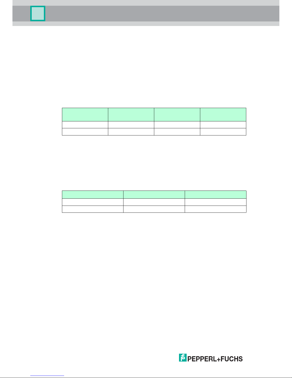
Optimum Read Distance
Hysteresis
If the read head has detected a colored tape, this colored tape can move in the Y direction from
the zero point within the viewing window. The maximum Y value at which the read head can
still capture this distance is designated as Y Value Out in the following table.
If the read head swivels onto a colored tape, the read head can capture the distance of the
colored tape from the zero point only if the tape is less than a certain distance away from the
zero point. This distance is designated as Y value In in the following table. The difference
between Y Value Out and Y Value In is the hysteresis. See "Distance Output" on page 17.
Order designation Read distance [mm] Depth of focus [mm]
Field of vision (w x h)
[mm]
PGV100* 100 ±20 117 x 75
PGV150I* 150 ±30 170 x 105
Order designation Max. Y Value Out [mm] Min. Y Value In [mm]
PGV100* 60 45
PGV150I* 60 60
Page 13
PGV...-F200/-F200A...-R4-V19
Installation
2019-03
13
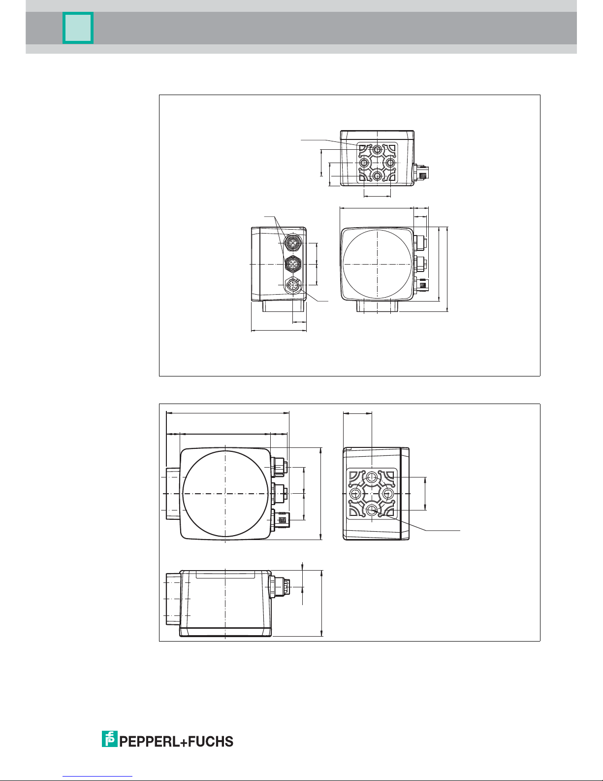
Read Head Dimensions
Figure 3.1 Housing *-F200-*
Figure 3.2 Housing *-F200A-*
12.5
54
2020
M12
M12
M6 x 9 (4x)
25
21.75
25
12
70 13.8
70
80
10 70 12
94.5
70
50
22
ø 25
M6 x 9 (4x)
12.5
20 20
Page 14
2019-03
14
PGV...-F200/-F200A...-R4-V19
Installation
3.2 Mounting the Colored Tape and Code Tape
Colored tape
The colored tape must be flexible, conformable, and resistant to abrasion, with a matte finish.
The colored tape must meet the following specifications:
Tape width: 10 mm ... 40 mm
Color of the tape
• Blue = RAL 5015
• Green = RAL 6032
• Red = RAL 3001
Tape thickness > 0.1 mm
The thickness of the tape is irrelevant to read head operation.
Breaking load > 25 N/cm
Breaking elongation > 180%
Adhesive strength > 2 N/cm
Temperature resistance: -20 °C ... 70 °C
Secure the colored tape to the floor such that the following conditions are met:
Data Matrix code tapes for positioning are used instead of the colored tape.
Data Matrix control codes are positioned parallel to the colored tape.
Color Selection
Select the color of the colored tape so that the contrast between the floor color and the color of
the colored tape is as great as possible. Ideally, use the complementary color.
Due to the integrated lighting of the read head, some floor colors appear to be different in the
camera. If you have problems with the color selection of the colored tapes, please consult your
contact at Pepperl+Fuchs.
Mounting the Colored Tape
1. Clean the surface of any greasy or oily deposits and dust.
2. Ensure that the surface is dry, clean, and stable.
3. Please observe the following section "Basics" when mounting the colored tape and, if
necessary, the instructions from the colored tape manufacturer.
Caution!
When selecting the length of the mounting screws, ensure that the maximum insertion depth of
the screws in the threaded inserts on the read head is 8 mm.
Using longer screws may damage the read head.
Caution!
The maximum torque of the mounting screws must not exceed 9 Nm.
Tightening the screws to a higher torque may damage the read head.
Note!
Priority
Data Matrix code tapes and Data Matrix tags have priority over colored tapes or colored lanes.
If the read head detects a Data Matrix code tape or Data Matrix tags in the field of view, colored
tapes or colored lanes in the field of view are ignored.
Page 15
PGV...-F200/-F200A...-R4-V19
Installation
2019-03
15
Cleaning Colored Tape/Code Tape
Significant contamination on the colored or code tapes can impair the detection by the read
head. Clean the colored and code tapes with isopropanol if necessary. If the contamination is
severe, you can use a non-corrosive plastic cleaner, e.g., Caramba®.
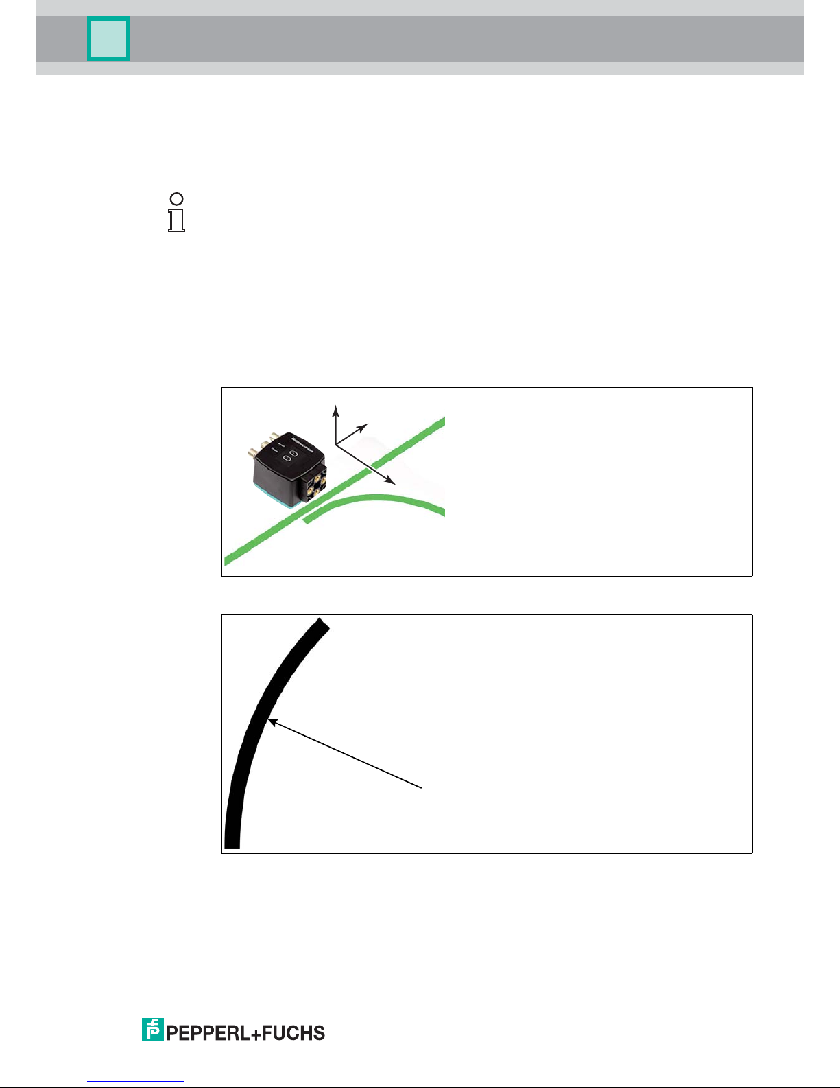
Basics
The read head detects a colored tape on a floor as a lane. The width of the colored tape must
be between 10 mm and 40 mm; the default width is 18 mm. The zero point is located in the
center of the colored tape. You can use 3 defined colors. See the section entitled "Colored
tape"
The sensor always moves in the X direction. In the sensor's field of view, X indicates an upward
movement.
Figure 3.3 Field of view and coordinates of the sensor
Figure 3.4 Curve radius: R 50 cm
Select a curve radius that can handle the turning circle of your automated guided vehicle. The colored tape must always
be located in the reading window of the read head.
Note!
To avoid polishing the surface, do not apply strong pressure when cleaning. A shiny surface of
the colored or code tapes leads to impairment in detection by the read head.
+Y
+X
+Z
R
Page 16
2019-03
16
PGV...-F200/-F200A...-R4-V19
Installation
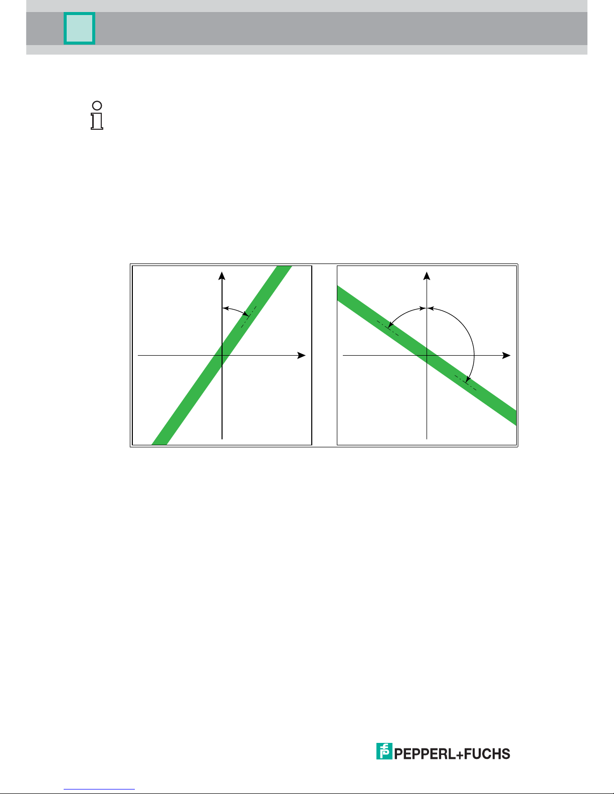
Angle Output
The read head detects a change of the angle of the colored tape and the Data Matrix code tape
and outputs this value to the controller. The output value is different for colored tapes and Data
Matrix code tapes.
Colored tape
The read head detects the angle in relation to the tracked lane with a resolution of 360
(corresponds to 1°). The angle is specified relative to the tracked lane because a colored tape
does not include any direction information. The output angle covers the range from -45° to 45°.
The resolution is 1°.
Figure 3.5 Relative angle
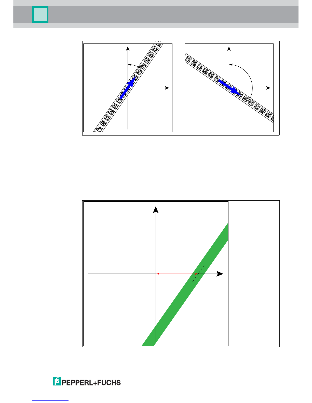
Data Matrix code tape
The read head detects the absolute angle in relation to the tracked lane with a maximum
resolution of 0.1°. The angle is specified absolutely relative to the tracked lane, since a Data
Matrix code contains tape direction information. The output angle covers the range from 0° to
360°. The resolution can be set to the following values:
0.1°
0.2°
0.5°
1°
Note!
Angles are specified as absolute values. The respective value is calculated from the resolution
selected under "Angle Resolution". With a resolution of 0.1°, an angle of 60° is output as
60°/0.1° = 600.
X
Y
α
X
Y
α
β
Page 17
PGV...-F200/-F200A...-R4-V19
Installation
2019-03
17
Figure 3.6 Absolute angle
Distance Output
The read head detects the distance from the zero point in the Y direction of a colored tape or a
Data Matrix code tape and outputs this value to the controller. The output value is different for
colored tapes and Data Matrix code tapes due to the lack of an X position for colored tapes.
Colored tape
The read head outputs the Y value at which the colored tape intersects the Y axis as the
distance.
Figure 3.7 Distance A for colored tape
X
Y
α
X
Y
α
X
Y
A
Page 18
2019-03
18
PGV...-F200/-F200A...-R4-V19
Installation
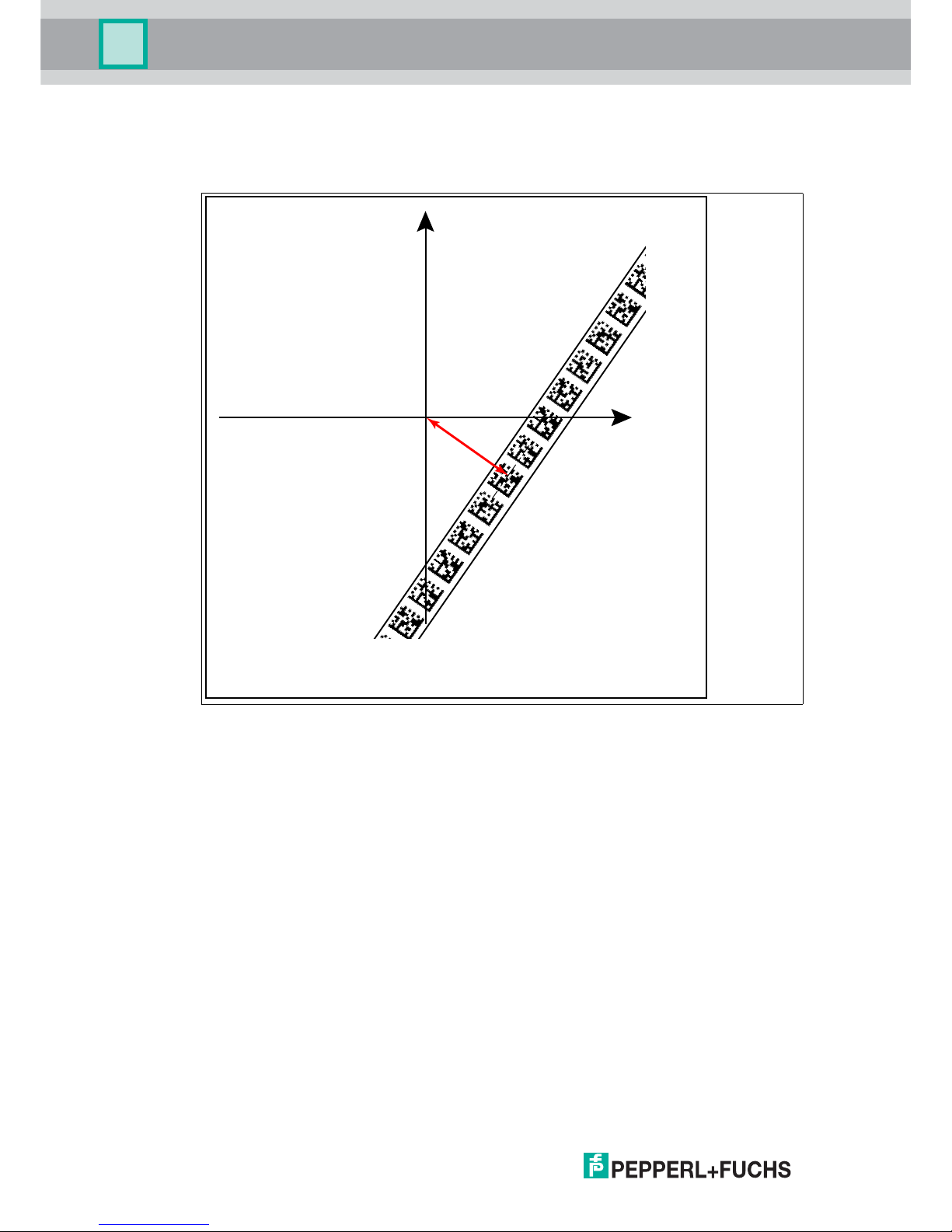
Data Matrix code tape
The read head indicates the vertical distance of the zero point in relation to the Data Matrix
code tape.
Figure 3.8 Distance A for Data Matrix code tape
X
Y
A
Page 19

PGV...-F200/-F200A...-R4-V19
Installation
2019-03
19
Branches
The read head detects one lane at the lower edge of the field of vision and two lanes at the
upper edge of the field of vision; the read head indicates this as a branch.
The read head detects two lanes at the lower edge of the field of vision and one lane at the
upper edge of the field of vision; the read head indicates this as an intersection.
Branches or intersections can be displayed as follows:
Figure 3.9 Separate lane branches off/converges
The read head can make the following direction decisions based on the lane and possible
branches:
Follow left-hand lane
Straight ahead
Follow right-hand lane
The direction decision is signaled to the read head via the controller. If there is no direction
decision, the read head displays an error message.
Code Tapes for Control and Positioning
In addition to tracking the lane, the read head can also detect Data Matrix codes. This process
involves evaluating both control and position information. Data Matrix control codes are used
as event markers. Control codes provide information on branches. Data Matrix code tapes for
positioning indicate the absolute position of the read head.
Note the following conditions:
Data Matrix code tapes for positioning are used instead of the colored tape.
Data Matrix control codes are used in tandem with the colored tape or Data Matrix position
code.
Page 20

2019-03
20
PGV...-F200/-F200A...-R4-V19
Installation
Branches or intersections with position information can be displayed as follows:
Figure 3.10 Separate lane branches off/converges
Colored tape
Data Matrix position code
Data Matrix control code
1
3
2
1
2
3
Page 21

PGV...-F200/-F200A...-R4-V19
Installation
2019-03
21
Figure 3.11 Same lane branches off/converges
Note!
Direction Decision
The direction decision at a branch of a Data Matrix code tape remains in effect until the read
head has moved more than 50 cm from the branch.
It is not possible to change the direction decision within a branch!
Note!
Priority
Data Matrix code tapes and Data Matrix tags have priority over colored tapes or colored lanes.
If the read head detects a Data Matrix code tape or Data Matrix tags in the field of view, colored
tapes or colored lanes in the field of view are ignored.
Note!
Branches/Intersections with Data Matrix Position Code
Observe the following guidelines less than 1 m before and after branching or intersection of a
lane with a position code:
The position codes of the main lane must run continuously for 2 m. The position codes of
the branching/intersecting lane must run continuously for 1 m. The read head outputs the
X-value of the Data Matrix code tape that is specified the direction decision. See chapter
4.1.
Do not use repair tape.
Do not use colored tape.
The difference between the absolute position of the main lane and the starting position of
the branching/intersecting lane must be greater than 1 m.
Page 22

2019-03
22
PGV...-F200/-F200A...-R4-V19
Installation
Figure 3.12 Distances
Behavior of the Read Head at Branches and Corners
The read head behaves differently depending on the type of branch and the specified lane.
The read head must know the upcoming direction decision.
A second lane branches off to the left from the straight lane:
The read head follows the straight lane if the direction decision "follow right-hand lane" has
been made.
A second lane branches off to the right from the straight lane:
The read head follows the straight lane if the direction decision "follow left-hand lane" has been
made.
A single lane with a position code turns to the left or right:
The read head follows the position code if the direction decision "straight ahead" has been
made.
1 m 1 m
1 m
Note!
Loss of Information
Ensure that Data Matrix codes are not positioned over one another at a branch, as otherwise
data may be lost.
Page 23

PGV...-F200/-F200A...-R4-V19
Installation
2019-03
23
It is not permitted to create a mixture of lanes made from colored tape and Data Matrix codes
at branches or intersections.
Figure 3.13 Mixture of lanes with colored tape and Data Matrix codes
Control codes can be mounted in the immediate vicinity of a branch with Data Matrix codes for
positioning, but not near an intersection. The control code must be mounted directly next to the
guiding lane.
Figure 3.14 Branch with control code
Page 24

2019-03
24
PGV...-F200/-F200A...-R4-V19
Installation
Distances
To ensure that the read head can clearly detect and assign colored tapes and Data Matrix
codes, minimum and maximum distances must be observed when creating the lanes.
Offset V between position codes of a lane must not be greater than 5 mm.
Figure 3.15 Offset: 0 mm V 5mm
The distance D between the colored tapes at a branch or intersection as a separate lane must
not exceed 15 mm. The distance decreases if the guiding colored tape cannot be detected by
the read head in the center of the reading window.
V
Page 25

PGV...-F200/-F200A...-R4-V19
Installation
2019-03
25
Figure 3.16 Distance: 7.5 mm D 15 mm
The distance between the Data Matrix code tapes at a branch or intersection as a separate
lane must be between 0 mm and 5 mm.
Figure 3.17 Distance: 0 mm D 5mm
Page 26

2019-03
26
PGV...-F200/-F200A...-R4-V19
Installation
The distance between a colored tape and a Data Matrix control code must be between 0 mm
and 5 mm.
Figure 3.18 0 mm D 5 mm
The distance between a Data Matrix position code and a Data Matrix control code must be
between 0 mm and 5 mm.
Figure 3.19 0 mm D 5 mm
A lane can switch from a colored tape to a Data Matrix code tape and back again as often as
required. The distance between the colored tape and the edge of the Data Matrix code must be
between 0 mm and 10 mm
25 mm D D 25 mm10...40 mm
25 mm D D 25 mm25 mm
Page 27

PGV...-F200/-F200A...-R4-V19
Installation
2019-03
27
Figure 3.20 0 mm D 10 mm
The Y value does not change if the colored tape and the Data Matrix code tape are aligned.
Ensure that the center line of the colored tape and the center line of the Data Matrix code are
on a line.
The code tape is made of silicone-free polyester film. A position marker appears every 100 mm
along the lower edge of the code tape (see "Code Tape Dimensions"). This position marker is
used for various functions, including precise positioning of the code tape during installation.
The reverse side of the code tape carries a permanent modified acrylate-based adhesive. Affix
the self-adhesive code tape along the desired travel path. To do so, proceed as follows:
Installing the Code Tape
1. Clean the surface of any greasy or oily deposits and dust.
2. Ensure that the surface is dry, clean, and stable.
3. Pull away a few centimeters of the protective film at the beginning of the code tape. Place
the code tape at the precise point of the required starting position on the surface, and press
to attach.
4. Then affix the code tape along the desired travel path. Remove the protective film gradually
so that the code tape does not accidentally adhere to the surface in the incorrect position.
When affixing, ensure that the code tape does not crease or trap air bubbles.
The adhesive on the code tape hardens after 72 hours.
D
D
Caution!
Alignment
The Data Matrix code is not on the center line of the code tape.
Note!
Thermal Expansion of the Code Tape
The affixed code tape corresponds to the heat expansion coefficient of the surface with regard
to its thermal expansion.
Page 28

2019-03
28
PGV...-F200/-F200A...-R4-V19
Installation
Figure 3.21 The center line indicates the center of the code tape and not the center of the code
Position the code tape so that the www.pepperl-fuchs.com label and the position markings
are to the right of the Data Matrix code in the X direction. The position values then increase
along the X direction.
Data Matrix Code Tapes with a Starting Position of 0 m
Data Matrix control codes
Code Tape Dimensions
Order designation Description
PGV10M-CA25-0 Code tape, length: 10 m
... ...
PGV100M-CA25-0 Code tape, length: 100 m
Table 3.1 See also data sheet PGV*-CA25-* at www.pepperl-fuchs.com
Order designation Description
PGV-CC25-001 Code tape, Control Code 001, length: 1 m
... ...
PGV-CC25-999 Code tape, Control Code 999, length: 1 m
Caution!
Stop edges
If you attach another code tape at the end of a previous code tape, the code pattern of 20 mm
must be retained.
Note!
Bends
If mounting the code tape in corners, cut the code tape several times as illustrated.
Page 29

PGV...-F200/-F200A...-R4-V19
Installation
2019-03
29
Data Matrix Tag
A Data Matrix tag contains position information in addition to a specific number. A cross in the
center of the Data Matrix tag marks the zero point. The X and the Y axes are marked starting
from the zero point. The black arrow indicates the positive axis and the white arrow indicates
the negative axis.
Figure 3.22 Data Matrix tag with the number 99999999 and position information
Bend to the left
Bend to the right
1
2
5
85
85
Page 30

2019-03
30
PGV...-F200/-F200A...-R4-V19
Installation
3.3 Electrical Connection
The read head is connected electrically via an 8-pin M12 x 1 connector on the side of the
housing. The power is supplied via this connection. The configurable inputs and outputs on the
read head are also located at this connection.
Figure 3.23
Figure 3.24
Color assignment
Pepperl+Fuchs female cordsets are manufactured in accordance with EN60947-5-2. When
using a type V19-... () female cordset with an open cable end on the Main connection, the
colors are assigned as follows:
Connector Assignment
Connection pin Strand color Color abbreviation
1 White WH
2 Brown BN
3 Green GN
4 Yellow YE
5 Gray GY
6 Pink PK
7 Blue BU
8 Red RD
1
2
3
4
5
6
7
8
INPUT_SELECTION_DIR_RIGHT
+ UB
Data+ / TX / 485+
Data- / RX / 485-
OUTPUT_LANE_PRESENT
INPUT_SELECTION_DIR_LEFT
- UB
IN/OUT 3
Main
1
4
6
7
8
53
2
Main
Page 31

PGV...-F200/-F200A...-R4-V19
Installation
2019-03
31
Shielding Cables
The shielding of connection lines is required to suppress electromagnetic interference.
Establishing a low resistance or low impedance connection with the protective conductor or
equipotential bonding circuit is a particularly important factor in ensuring that these
interference currents do not become a source of interference themselves. Only use connection
lines with braid. Avoid connection lines with foil shield because this would increase the line
capacities. The shielding is integrated at both ends, i.e., in the switch cabinet, on the PLC, and
on the reader. The grounding terminal available as an accessory allows easy integration in the
equipotential bonding circuit.
In exceptional cases, the shielding of a connection at one end may be more favorable if:
An equipotential bonding cable is not laid or cannot be laid.
A film shield is used.
The following points relating to shielding must also be noted:
Use metal cable clips that cover large areas of the shield.
After installing the cable shield in the control cabinet, place it directly on the equipotential
bonding rail.
Direct the protective grounding connections to a common point in a star configuration.
The cross-section of the cables used for grounding should be as large as possible.
Additional Ground Connection
Order designation Description
PCV-SC12 Clip for mounting an additional ground
connection.
PCV-SC12A
Caution!
Damage to the device
Connecting an alternating current or excessive supply voltage can damage the device or
cause the device to malfunction.
Electrical connections with reversed polarity can damage the device or cause the device to
malfunction.
Connect the device to direct current (DC). Ensure that the supply voltage rating is within the
specified device range. Ensure that the connecting wires on the female cordset are connected
correctly.
Page 32

2019-03
32
PGV...-F200/-F200A...-R4-V19
Commissioning
4 Commissioning
4.1 Specifying the First Direction Decision
To ensure that the read head does not report any error messages after being switched on, a
direction decision must be specified. You can control the direction decision via the
INPUT_SELECTION_DIR_RIGHT and INPUT_SELECTION_DIR_LEFT inputs. See chapter
3.3.
Figure 4.1
Direction decision via protocol
If a decision on the direction to take is sent to the read head via a protocol, the input signals are
ignored until the read head is reset. See chapter 5.1.
4.2 Direction Decision
The read head has several ways of following colored tapes and Data Matrix code tapes
depending on the parameterization. Depending on the input signal, the read head follows the
right-hand, the left-hand, or the better lane.
Direction Decision via Input Signal
t
1
0
1
0
INPUT_SELECTION_DIR_RIGHT
INPUT_SELECTION_DIR_LEFT
Direction decision
≥ 20 ms
Error 5 Left Error 5LeftRight
Input 2
INPUT_SELECTION_DIR_LEFT
Input 1
INPUT_SELECTION_DIR_RIGHT
Direction Decision
0 0 No lane is selected
Error code 5
0 1 Follow right-hand lane
1 0 Follow left-hand lane
1 1 Colored tape: follow lane with better quality
Data Matrix code tape: follow lane with more detailed position information
Data Matrix tag: no significance
Table 4.1
Page 33

PGV...-F200/-F200A...-R4-V19
Commissioning
2019-03
33
Following Lane with Better Quality
You can parameterize the read head so that it follows the better quality color lane.
Figure 4.2 - Better color lane
- Worse color lane
Following Lane with More Detailed Position Information
You can parameterize the read head so that it follows the Data Matrix code tape that continues
the current location information.
Figure 4.3 - More detailed position information
- New position Information
Example
Example
11 2 2
1
2
108
110
112
114
116
398
400
118
402
404
406
408
120
122
124
12
1
2
Page 34

2019-03
34
PGV...-F200/-F200A...-R4-V19
Commissioning
4.3 Parameter assignment
The reading head can be adapted to specific requirements through parameterization. The
reading head can be parameterized via the interface itself (internal parameterization) or via an
optical parameterization code (external parameterization).
4.3.1 Internal Parameterization Using Parameterization Software
Internal parameterization of the reader via the USB interface must be started within 10 minutes
of the reader being switched on. A time lock disables the reader once this time has elapsed.
The time lock remains inactive during the parameterization process. The time lock disables the
reader only if no parameterization activities take place for more than 10 minutes.
The Vision Configurator software is available for comprehensive, optimal configuration of the
reader. This configuration software is available as a free download from www.pepperlfuchs.com. Follow the instructions that appear on your screen during the installation.
If your PC does not have a built-in RS-485 interface, you will need a USB/RS-485 interface
converter ().
Parameterizing the Reader
1. Connect the reader to your PC via the interface converter. Information on how to do this can
be found in the manual for the interface converter.
2. Connect the reader to a suitable power supply.
3. Switch on the power supply.
4. Start the "Vision Configurator" software.
5. Configure the reader using the "Vision Configurator" software.
6. Transfer the parameter list to the reader.
7. Save the parameterization.
8. Switch off the power supply on the reader.
9. Disconnect the reader from the interface converter and from the power supply.
The reader is parameterized according to your specifications and can be used in your
application.
Note!
Additional steps for customizing the installation are described in the Vision Configurator
manual. The Vision Configurator manual can be found online at www.pepperl-fuchs.com.
Page 35

PGV...-F200/-F200A...-R4-V19
Commissioning
2019-03
35
4.3.2 External Parameterization Using Code Cards
During external parameterization, the reader scans special code cards optically and configures
the relevant parameters. Simply hold the corresponding code cards at the correct distance in
front of the lens on the reader. The standard code cards are in the appendix.
The following parameters can be configured using code cards:
Reader resolution [0.1 mm, 1 mm, 10 mm]
Reader orientation [0°; 180°; 0° or 180°, 0°, 90°, 180° or 270°]
Trigger source [auto, hardware]
Function of input 1 [none, trigger input]
Function of output 1 [none, speed exceeded, warning, fault, contamination, event, no
position]
Function of output 2 [none, speed exceeded, warning, fault, contamination, event, no
position]
Function of output 3 [none, speed exceeded, warning, fault, contamination, event, no
position]
Activating Programming Mode
The changeover from normal operation to parameterization mode is made by pressing button 2
on the back of the reader.
Activating Parameterization Mode
1. Press button 2 for longer than 2 seconds.
Yellow LED3 now flashes.
2. Hold the "ENABLE" code in front of the camera system on the reader to trigger final
activation
If the "ENABLE" activation code is detected, the green LED2 lights up for 1 second. If
the activation code is not detected, LED2 lights up red for 2 seconds.
Completing Parameterization
Place the parameterization code in the field of vision of the camera module.
After the parameterization code is detected, the green LED2 lights up for 1 second. In the
event of an invalid parameterization code, LED2 lights up red for 2 seconds.
Exiting Parameterization Mode
Hold the "STORE" code in front of the camera system on the reader to save the configuration
If the "STORE" memory code is detected, the green LED2 lights up for 1 second. The
parameterization is stored in the nonvolatile memory of the reader and parameterization mode
is terminated. Parameterization of the reader is now complete. If the memory code is not
detected, LED2 lights up red for 2 seconds.
Note!
External parameterization of the reader using code cards must be started within 10 minutes of
the reader switching on. A time lock disables the reader once this time has elapsed. The time
lock remains inactive during the parameterization process. The time lock disables the reader
only if no parameterization activities take place for more than 10 minutes.
If a button is pressed when the time lock is enabled, all LEDs flash and remain lit for 2 seconds
during each flashing cycle.
Page 36

2019-03
36
PGV...-F200/-F200A...-R4-V19
Commissioning
The code cards "CANCEL", "USE", and "DEFAULT"
Holding one of these cards in front of the reading head exits parameterization mode with the
following consequences:
CANCEL:
All parameter changes that are made but have not yet been saved are discarded. The
reading head operates with the last valid parameters that were saved.
USE:
For test purposes, the reading head operates with the parameters that have just been
modified. The parameterization is not saved, however. After being switched off and on
again, the reading head operates with the last valid parameters that were saved.
DEFAULT:
All parameters in the reading head are overwritten with the original default settings. Reenter the configuration mode and save the default settings nonvolatile with the code card
STORE.
Note!
Press button 2 briefly to exit parameterization mode. Any parameter changes that are made
but have not yet been saved are discarded. The reader then operates with the last valid
parameters that were saved.
Page 37

PGV...-F200/-F200A...-R4-V19
Operation and communication
2019-03
37
5 Operation and communication
5.1 Communication via the RS-485 Interface
The controller and read head communicate via the RS-485 interface during operation. Make
sure that the basic communication settings have been made on the read head, such as setting
the read head address and baud rate.
A distinction is made between request telegrams that the controller sends to the read head and
response telegrams that the read head sends to the controller. Each byte of a request or
response telegram consists of 9 bits (8 data bits + 1 parity bit).
5.1.1 Request Telegram
A request telegram always consists of 2 bytes. The second byte corresponds to the first byte,
but with the 8 data bits of the first byte inverted.
Structure of a Request Telegram
Meaning of Bits
Byte/bit Bit 8 Bit 7 Bit 6 Bit 5 Bit 4 Bit 3 Bit 2 Bit 1 Bit 0 Function
Byte 1 Parity
1
1
1.R/W: 0 = response, 1 = request
Req.
bit 4
Req.
bit 3
Req.
bit 2
Req.
bit 1
Req.
bit 0
A1 A0 Request
Byte 2 Parity 0 ~Req.
bit 4
~Req.
bit 3
~Req.
bit 2
~Req.
bit 1
~Req.
bit 0
~A1 ~A0 Checksum
PAR R/W
Req.
bit 4
Req.
bit 3
Req.
bit 2
Req.
bit 1
Req.
bit 0
A1 A0 Function
Parity 1 x x x x x 0 0 Read head address 0
Parity 1 x x x x x 0 1 Read head address 1
Parity 1 x x x x x 1 0 Read head address 2
Parity 1 x x x x x 1 1 Read head address 3
Parity 1 1 0 0 1 0 x x Position inquiry
See chapter 5.1.2
Parity 1 0 0 0 LL RL x x Selection of direction
See chapter 5.1.3
Parity 1 1 0 R=0 G=0 B=1 x x Choice of color blue
See chapter 5.1.4
Parity 1 0 0 R=0 G=1 B=0 x x Choice of color green
See chapter 5.1.4
Parity 1 0 0 R=1 G=0 B=0 x x Choice of color red
See chapter 5.1.4
Page 38

2019-03
38
PGV...-F200/-F200A...-R4-V19
Operation and communication
5.1.2 Position Response Telegram
A response telegram is 21 bytes long. Bytes 1 and 2 contain the read head address and status
information.
Response telegram from the read head – lane tracking
Bit 8 Bit 7 Bit 6 Bit 5 Bit 4 Bit 3 Bit 2 Bit 1 Bit 0
Byte 1 Parity 0 CC2 A1 A0 CC1 WRN NP ERR
Byte 2 Parity 0
TAG [0]
1
LC1 LC0 RP NL LL RL
Byte 3 Parity 0 Reserved Reserved Reserved Reserved XP23 XP22 XP21
Byte 4 Parity 0 XP20 XP19 XP18 XP17 XP16 XP15 XP14
Byte 5 Parity 0 XP13 XP12 XP11 XP10 XP09 XP08 XP07
Byte 6 Parity 0 XP06 XP05 XP04 XP03 XP02 XP01 XP00
Byte 7 Parity 0 YPS13 YPS12 YPS11 YPS10 YPS09 YPS08 YPS07
Byte 8 Parity 0 YPS06 YPS05 YPS04 YPS03 YPS02 YPS01 YPS00
Byte 9 Parity 0 Reserved Reserved Reserved Reserved Reserved Reserved Reserved
Byte 10 Parity 0 Reserved Reserved Reserved Reserved Reserved Reserved Reserved
Byte 11 Parity 0 ANG13 ANG12 ANG11 ANG10 ANG09 ANG08 ANG07
Byte 12 Parity 0 ANG06 ANG05 ANG04 ANG03 ANG02 ANG01 ANG00
Byte 13 Parity 0 Reserved Reserved Reserved Reserved Reserved Reserved Reserved
Byte 14 Parity 0 Reserved Reserved Reserved Reserved Reserved Reserved Reserved
Byte 15 Parity 0 O1_1 O1_0 S1_1 S1_0 CC1_09 CC1_08 CC1_07
Byte 16 Parity 0 CC1_06 CC1_05 CC1_04 CC1_03 CC1_02 CC1_01 CC1_00
Byte 17 Parity 0 O2_1 O2_0 S2_1 S2_0 CC2_09 CC2_08 CC2_07
Byte 18 Parity 0 CC2_06 CC2_05 CC2_04 CC2_03 CC2_02 CC2_01 CC2_00
Byte 19 Parity 0 WRN13 WRN12 WRN11 WRN10 WRN09 WRN08 WRN07
Byte 20 Parity 0 WRN06 WRN05 WRN04 WRN03 WRN02 WRN01 WRN00
Byte 21 Parity 0 XOR
B1.6
...
B20.6
XOR
B1.5
...
B20.5
XOR
B1.4
...
B20.4
XOR
B1.3
...
B20.3
XOR
B1.2
...
B20.2
XOR
B1.1
...
B20.1
XOR
B1.0
...
B20.0
Table 5.1
1.If bit = 0: read head follows color/Data Matrix lane
Page 39

PGV...-F200/-F200A...-R4-V19
Operation and communication
2019-03
39
Response telegram from the read head - Data Matrix tag
Bit 8 Bit 7 Bit 6 Bit 5 Bit 4 Bit 3 Bit 2 Bit 1 Bit 0
Byte 1 Parity 0 CC2 A1 A0 CC1 WRN NP ERR
Byte 2 Parity 0
TAG [1]
1
LC1 LC0 RP NL LL RL
Byte 3 Parity 0 Reserved Reserved Reserved Reserved XPS23 XPS22 XPS21
Byte 4 Parity 0 XPS20 XPS19 XPS18 XPS17 XPS16 XPS15 XPS14
Byte 5 Parity 0 XPS13 XPS12 XPS11 XPS10 XPS09 XPS08 XPS07
Byte 6 Parity 0 XPS06 XPS05 XPS04 XPS03 XPS02 XPS01 XPS00
Byte 7 Parity 0 YPS13 YPS12 YPS11 YPS10 YPS09 YPS08 YPS07
Byte 8 Parity 0 YPS06 YPS05 YPS04 YPS03 YPS02 YPS01 YPS00
Byte 9 Parity 0 Reserved Reserved Reserved Reserved Reserved Reserved Reserved
Byte 10 Parity 0 Reserved Reserved Reserved Reserved Reserved Reserved Reserved
Byte 11 Parity 0 ANG13 ANG12 ANG11 ANG10 ANG09 ANG08 ANG07
Byte 12 Parity 0 ANG06 ANG05 ANG04 ANG03 ANG02 ANG01 ANG00
Byte 13 Parity 0 Reserved Reserved Reserved Reserved Reserved Reserved Reserved
Byte 14 Parity 0 Reserved Reserved Reserved Reserved Reserved Reserved Reserved
Byte 15 Parity 0 TAG_27 TAG_26 TAG_25 TAG_24 TAG_23 TAG_22 TAG_21
Byte 16 Parity 0 TAG_20 TAG_19 TAG_18 TAG_17 TAG_16 TAG_15 TAG_14
Byte 17 Parity 0 TAG_13 TAG_12 TAG_11 TAG_10 TAG_09 TAG_08 TAG_07
Byte 18 Parity 0 TAG_06 TAG_05 TAG_04 TAG_03 TAG_02 TAG_01 TAG_00
Byte 19 Parity 0 WRN13 WRN12 WRN11 WRN10 WRN09 WRN08 WRN07
Byte 20 Parity 0 WRN06 WRN05 WRN04 WRN03 WRN02 WRN01 WRN00
Byte 21 Parity 0 XOR
B1.6
...
B20.6
XOR
B1.5
...
B20.5
XOR
B1.4
...
B20.4
XOR
B1.3
...
B20.3
XOR
B1.2
...
B20.2
XOR
B1.1
...
B20.1
XOR
B1.0
...
B20.0
Table 5.2
1.If bit = 1: read head detects Data Matrix tag
Note!
Sign
If the read head is following a lane, the specification of the X position is unsigned.
If the read head is above a Data Matrix tag, the X position is signed.
Page 40

2019-03
40
PGV...-F200/-F200A...-R4-V19
Operation and communication
Error Codes
Designation Function
A Address of the read head
ANG Absolute angle specification
CC1/CC2_#_# Control code 1 or 2 with number # detected
Control code 2 is evaluated via the "Split value" function.
1
1.Should you have any questions, please contact Pepperl+Fuchs
CC1/CC2 Associated control code is detected.
ERR Fault message
Error codes are stored in XP00 ... XP23. Additional information on the codes
can be found in the Error Codes table.
LC Number of lanes in the reading window. Refer to section "Number of Lanes
LC"
LL/RL Selected direction decision
NL No colored lane detected
NP No absolute X position
O1_#/O2_# Orientation control code for lane. Refer to section "Orientation O"
RP Repair tape detected
S1_#/S2_# Relative position control code for lane. Refer to section "Side S"
TAG Data Matrix tag detected
TAG_# Data Matrix tag with number # detected
WRN Warning message
Warnings are stored in WRN00 ... WRN13. Additional information on the
codes can be found in the Warning Messages table.
XP Absolute position in the X direction, unsigned
XPS Absolute position in the X direction, signed
YPS Absolute position in the Y direction, signed
Table 5.3
Error code Description Priority
2 No clear position can be determined, e.g., difference between
codes is too great, code distance incorrect
4
5 No direction decision available, see chapter 4.1, see chapter
5.1.3
2
6 No color choice available, see chapter 5.1.4 3
> 1000 Internal fault 1
Table 5.4
Page 41

PGV...-F200/-F200A...-R4-V19
Operation and communication
2019-03
41
Warning Messages
Number of Lanes LC (Lane Count)
The lane count, LC, indicates the number of found fab or Data Matrix tracks in the reading
window. A variety of causes may be responsible if the lane count does not match the expected
number of lanes:
LC < actual number
Lane is not located in the reading window
Color of the lane does not match the configured color
LC > actual number
Contrast between the ribbon and the floor is too low
Warning
message
Description
WRN00 Code with content not typical of PGV found
WRN01 Read head too close to code tape
WRN02 Read head too far from code tape
WRN03 Reserved
WRN04 Reserved
WRN05 The read head is rotated or tipped in relation to the code tape
WRN06 Low level of code contrast
WRN07 Repair tape detected
WRN08 Temperature too high
WRN09 Position code near branch/crossover detected
WRN10 More than the specified number of code lanes present
WRN11 Reserved
WRN12 Reserved
WRN13 Reserved
Table 5.5 If no warnings are present, the bits are set to 0.
Note!
16-bit/32-bit
In order for the response telegrams from the read head to be transferred in 16-bit or 32-bit
values, fill in the missing bits as follows:
1. Unsigned: Fill in the missing upper bits with "0".
2. Signed: Fill in the missing upper bits with the highest bit of the response telegram.
Should you have any questions about this, please contact Pepperl+Fuchs.
Tip
Increase contrast
To ensure maximum contrast between the floor and the ribbon, please note the following
contrast colors:
Basic color green: contrast color red
Basic color blue: contrast color red
Basic color red: contrast color green
Page 42

2019-03
42
PGV...-F200/-F200A...-R4-V19
Operation and communication
Meaning of Bits
Orientation O
The orientation O indicates the orientation of the control codes in the reading window.
Meaning of Bits
Figure 5.1
LC1 LC0 Meaning
0 0 No lane found
0 1 1 lane found
1 0 2 lanes found
1 1 3 or more lanes found
O1 O0 Meaning
0 0 Control code has the same orientation as
ascending Data Matrix lane
0 1 Orientation of control code rotated 90° clockwise
in relation to ascending Data Matrix lane
1 0 Orientation of control code rotated 180° clockwise
in relation to ascending Data Matrix lane
1 1 Orientation of control code rotated 270° clockwise
in relation to ascending Data Matrix lane
Orientation
X
Y
O1=0
O0=0
O1=1
O0=0
O1=0
O0=1
O1=1
O0=1
Page 43

PGV...-F200/-F200A...-R4-V19
Operation and communication
2019-03
43
Side S
Side S specifies the side of the Data Matrix lane on which the control codes are present.
Meaning of Bits
Figure 5.2 Control code to the right of the Data Matrix or color lane
Position/Lane
You can use the following table to draw conclusions on the current section in the reading
window from the feedback of the read head regarding Data Matrix TAG, No Lane NL, No X
Position NP, absolute X position XP and the Y position and angle YPS/ANG.
Meaning of Bits
S1 S0 Meaning
0 0 No control code is present or found
Reserved
0 1 Control code to the right of the Data Matrix or color
lane
1 0 Control code to the left of the Data Matrix or color
lane
1 1
Not detectable
1
1. Control code laid on Data Matrix lane, No Data Matrix lane
Example
TAG NL NP XP YPS/ANG Meaning
0 0 0
+
1
1.Valid data present
+ Color and Data Matrix lane present.
Position and angle refer to the Data
Matrix lane.
0 0 1
-
2
2.No valid data available
+ Color lane available.
0 1 0 + + Data Matrix lane.
0 1 1 - - No evaluable objects exist.
1 - 0 + + Position on the basis of a Data Matrix
tag, X position is signed.
Page 44

2019-03
44
PGV...-F200/-F200A...-R4-V19
Operation and communication
5.1.3 Direction Decision Request Telegram
Response Telegram for Direction Decision
Meaning of Bits
5.1.4 Color Choice Request Telegram
Blue
Green
Byte/bit Bit 8 Bit 7 Bit 6 Bit 5 Bit 4 Bit 3 Bit 2 Bit 1 Bit 0 Function
Byte 1 Parity 1 1 1 0 LL RL A1 A0 Request
Byte 2 Parity 0 0 0 1 ~LL ~RL ~A1 ~A0 Checksum
Bit 8 Bit 7 Bit 6 Bit 5 Bit 4 Bit 3 Bit 2 Bit 1 Bit 0
Byte 1 Parity 0 CC2 A1 A0 CC1 WRN NP ERR
Byte 2 Parity 0 0 0 0 0 0 LL RL
Byte 3 Parity 0 XOR
B1.6
...
B2.6
XOR
B1.5
...
B2.5
XOR
B1.4
...
B2.4
XOR
B1.3
...
B2.3
XOR
B1.2
...
B2.2
XOR
B1.1
...
B2.1
XOR
B1.0
...
B2.0
LL RL Meaning
0 0 Error code 5
0 1 Follow right-hand lane
1 0 Follow left-hand lane
1 1 Straight ahead
Table 5.6 See chapter 4.2
Example!
Request telegram when read head address = 0
Request Response Description Example
0xE8, 0x17 See "Response Telegram for
Direction Decision"
Follow left-hand lane --"0x02"--
0xE4, 0x1B Follow right-hand lane --"0x01"--
0xEC, 0x13 Straight ahead --"0x03"--
0xE0, 0x1F No lane is selected
Error code 5
--"0x00"--
Byte/bit Bit 8 Bit 7 Bit 6 Bit 5 Bit 4 Bit 3 Bit 2 Bit 1 Bit 0 Function
Byte 1 Parity 1 1 0 R=0 G=0 B=1 A1 A0 Request
Byte 2 Parity 0 0 1 1 1 0 ~A1 ~A0 Checksum
Byte/bit Bit 8 Bit 7 Bit 6 Bit 5 Bit 4 Bit 3 Bit 2 Bit 1 Bit 0 Function
Byte 1 Parity 1 0 0 R=0 G=1 B=0 A1 A0 Request
Byte 2 Parity 0 1 1 1 0 1 ~A1 ~A0 Checksum
Page 45

PGV...-F200/-F200A...-R4-V19
Operation and communication
2019-03
45
Red
Response telegram for color choice
Meaning of Bits
Byte/bit Bit 8 Bit 7 Bit 6 Bit 5 Bit 4 Bit 3 Bit 2 Bit 1 Bit 0 Function
Byte 1 Parity 1 0 0 R=1 G=0 B=0 A1 A0 Request
Byte 2 Parity 0 1 1 0 1 1 ~A1 ~A0 Checksum
Note!
You can only ever request one color.
Byte/bit Bit 8 Bit 7 Bit 6 Bit 5 Bit 4 Bit 3 Bit 2 Bit 1 Bit 0
Byte 1 Parity 0 0 A1 A0 0 R G B
Byte 2 Parity 0 0 A1 A0 0 R G B
R G B Meaning
0 0 1 Choice of color blue
0 1 0 Choice of color green
1 0 0 Choice of color red
Example!
Request telegram when read head address = 0
Request Response Description
0xC4, 0x3B 0x01, 0x01 Choice of color blue
0x88, 0x77 0x02, 0x02 Choice of color green
0x90, 0x6F 0x04, 0x04 Choice of color red
Page 46

2019-03
46
PGV...-F200/-F200A...-R4-V19
Operation and communication
5.2 Operation Using Control Codes
In numerous positioning system applications, defined processes (= event) must be started at
specific positions. This means that the exact positions must be defined via code tapes for
positioning, instead of simple colored tapes. In the context of lane tracking, it is advisable to
mark branches using control codes to facilitate the control of the direction decision.
The layout of the lane can be adjusted according to the application in question. If an automated
guided vehicle must be positioned exactly, a code tape is mounted for positioning purposes
instead of the colored tape. If an event needs to start at a particular position or a direction
decision needs to be made, a control code is mounted parallel to the actual lane.
Only a specific event and the associated process then have to be programmed into the system
controller. The position in which the corresponding control code is placed next to the colored
tape or code tape for positioning does not have to be determined until final commissioning.
Even if subsequent changes are made to the layout of a system, the relevant control code is
simply moved to the new position without requiring program modifications to be made.
Control codes are short code tapes one meter in length. The control code has an encrypted
number. Control codes exist with numbers ranging from 001 to 999.
When the read head enters the range of a control code, it sets the control code flag in its output
data.
The 1-meter-long control code can be shortened. However, the minimum length should be 3
codes (60 mm). If the speed of the read head increases, a longer control code is required. If the
read head travels at maximum speed, a full-length control code of 1 meter must be positioned
next to the colored tape or code tape for positioning.
The minimum length of a control code can be calculated according to the following formula
depending on the travel speed and trigger period:
L
control code
= 60 mm + V
max
[m/s] * T
Trigger
[s] x 2
The trigger period is 40 ms.
Control codes are identified by the printed number, in this case "Control 12".
Figure 5.3 PGV-CC25-0012
The illustration shows part of control code #12
Refer to the "Accessories" chapter for order information relating to control codes.
Example!
Example calculation
The minimum length of the control code at a speed of 3 m/s and a trigger period of 40 ms is:
L
Event marker
= 60 mm + 3 m/s * 40 ms * 2 = 300 mm
Page 47

PGV...-F200/-F200A...-R4-V19
Operation and communication
2019-03
47
5.3 Operation Using Repair Tape
The repair tape is a short code tape one meter in length. The repair tape is used to bridge
defective or damaged areas of an existing code tape.
1. Cut the repair tape to the required length
2. Cover the defective area of the existing code tape with the repair tape
When the read head enters the range of a repair tape, it sets the repair tape flag in its output
data.
Refer to the "Accessories" chapter for order information relating to repair tape.
Note!
When placing a repair tape on the code tape, make sure that the repair tape continues the
pattern on the code tape as accurately as possible.
Note!
The repair tape works incrementally. In so doing, it adds one value to the previous read
position on the code tape. If the read head starts on a repair tape, the read head reports an
error. Move the read head to a position on the code tape away from the repair tape to read the
absolute value.
Tip
If repairs are required, the Code Tape Generator at www.pepperl-fuchs.com can be used as
a short-term workaround. This generator enables segments of code tape to be produced and
printed out online.
Enter the start value in meters and the code tape length of the section to be replaced in meters.
This produces a printable PDF file containing the required segment of the code tape.
The printout must be used only as an emergency solution. The durability of the paper strip is
extremely limited depending on the application!
Page 48

2019-03
48
PGV...-F200/-F200A...-R4-V19
Appendix
6Appendix
6.1 Code Cards for External Parameterization
Here, you can find the code cards that enable you to parameterize some basic read head
functions step by step. For the exact external parameterization procedure .
6.1.1 Code Cards with Special Functions
The following code cards have special functions:
ENABLE
STORE
CANCEL
USE
DEFAULT
Figure 6.1 The code card "ENABLE" is used to activate external parameterization operating
mode.
Note!
When performing external parameterization with code cards, we recommend copying and
printing out the relevant pages in this manual and cutting out the code cards. This prevents the
read head from mistakenly detecting another code card on the same page. If you intend to use
this manual directly for parameterization, cover the code cards that you do not require with a
sheet of paper, for example.
Enable
Page 49

PGV...-F200/-F200A...-R4-V19
Appendix
2019-03
49
Figure 6.2 The "STORE" code card stores the modified parameterization in the nonvolatile
memory of the read head and terminates external parameterization operating mode.
Figure 6.3 The "CANCEL" code card discards the modified parameterization and terminates
external parameterization operating mode. The read head switches to normal mode
and adopts the last valid configuration that was saved.
Store
Cancel
Store
Cancel
Page 50

2019-03
50
PGV...-F200/-F200A...-R4-V19
Appendix
Figure 6.4 The "USE" code card takes over the set configuration volatile in the read head working
memory and terminates the external parameterization operating mode. The read head
then operates with this configuration. However, if the read head is switched off and on
again, the configuration is lost and the read head operates with the last valid
configuration that was saved. This function is used primarily for test purposes.
Figure 6.5 The "DEFAULT" code card restores the settings of the read head to default and
terminates external parameterization operating mode.
Use
Default
Use
Default
Page 51

PGV...-F200/-F200A...-R4-V19
Appendix
2019-03
51
6.1.2 Code Cards for Setting the Read Head Address
A unique address must be assigned to the read head so that it can be activated via the
interface. The address range extends from 0 ... 3.
Figure 6.6 The code card assigns address 0 to the read head.
Figure 6.7 The code card assigns address 1 to the read head.
Figure 6.8 The code card assigns address 2 to the read head.
Read Head Address 0
Read Head Address 1
Read Head Address 2
Adresse 0
Adresse 1
Adresse 2
Page 52

2019-03
52
PGV...-F200/-F200A...-R4-V19
Appendix
Figure 6.9 The code card assigns address 3 to the read head.
6.1.3 Code Cards for Adjusting the Resolution
Parameterization enables you to assign a position data resolution of 0.1 mm / 1 mm / 10 mm to
the read head.
Figure 6.10 The code card assigns a position data resolution of 0.1 mm to the read head.
Figure 6.11 The code card assigns a position data resolution of 1 mm to the read head.
Read Head Address 3
Adresse 3
Resolution: 0.1 mm
Resolution: 1 mm
Resolution
0.1 mm
Resolution
1 mm
Page 53

PGV...-F200/-F200A...-R4-V19
Appendix
2019-03
53
Figure 6.12 The code card assigns a position data resolution of 10 mm to the read head.
Maximum Length of the Code Tape
6.1.4 Code cards for setting the transfer rate
Parameterization allows you to assign various transfer rates to the reading head for
communication via the interface. The following transfer rates are available:
38400 bit/s
57600 bit/s
76800 bit/s
115200 bit/s
230400 bit/s
Figure 6.13 The transfer rate of the read head for communication via the interface is preset to
38400 bit/s.
Resolution: 10 mm
Resolution of the read head [mm] Maximum length of the code tape [km]
10 10
1 10
0.1 10
Resolution
10 mm
Transfer rate: 38400 bit/s
38400 Bit/s
Page 54

2019-03
54
PGV...-F200/-F200A...-R4-V19
Appendix
Figure 6.14 The transfer rate of the read head for communication via the interface is preset to
57600 bit/s.
Figure 6.15 The transfer rate of the read head for communication via the interface is preset to
76800 bit/s.
Figure 6.16 The transfer rate of the read head for communication via the interface is preset to
115200 bit/s.
Transfer rate: 57600 bit/s
Transfer rate: 76800 bit/s
Transfer rate: 115200 bit/s
57600 Bit/s
76800 Bit/s
115200 Bit/s
Page 55

PGV...-F200/-F200A...-R4-V19
Appendix
2019-03
55
Figure 6.17 The transfer rate of the read head for communication via the interface is preset to
230400 bit/s.
6.1.5 Code cards for adjusting the terminator
Parameterization enables you to switch a terminator on and off in the read head:
Figure 6.18 The terminator is deactivated.
Figure 6.19 The terminator is connected.
Transfer rate: 230400 bit/s
230400 Bit/s
Terminator: OFF
Terminator: ON
Termination
off
Termination
on
Page 56

2019-03
56
PGV...-F200/-F200A...-R4-V19
Appendix
6.1.6 Code Cards for Adjusting Input/Output 3
Parameterization enables you to assign various functions to input/output 3 on the read head.
The following input/output functions are available:
Input: none
Output: Overspeed
Output: Warning
Output: Fault
Output: Event
Output: No position
Figure 6.20 Input/output 3 is defined as an input but has no function.
Figure 6.21 Input/output 3 is defined as an output. This output carries the potential +UB as long as
the defined maximum speed is exceeded.
Input 3: No Function
Output 3: Overspeed
Input 3
No function
Output 3
Overspeed
Page 57

PGV...-F200/-F200A...-R4-V19
Appendix
2019-03
57
Figure 6.22 Input/output 3 is defined as an output. This output carries the potential +UB as long as a
warning message is present in the read head.
Figure 6.23 Input/output 3 is defined as an output. This output carries the potential +U
B
as long as
an error message is present on the read head.
Figure 6.24 Input/output 3 is defined as an output. This output carries the potential +U
B
as long as
an event marker is present in the read field of the read head.
Output 3: Warning
Output 3: Fault
Output 3: Event
Output 3
Warning
Output 3
Error
Output 3
Event
Page 58

2019-03
58
PGV...-F200/-F200A...-R4-V19
Appendix
Figure 6.25 Input/output 3 is defined as an output. This output carries the potential +UB as long as
the read head is not reading any position information.
Output 3: No position
Output 3
No position
Page 59

Subject to modifications
Copyright PEPPERL+FUCHS • Printed in Germany
www.pepperl-fuchs.com
FACTORY AUTOMATION –
SENSING YOUR NEEDS
Worldwide Headquarters
Pepperl+Fuchs GmbH
68307 Mannheim
· Germany
Tel. +49 621 776-0
E-mail: info@de.pepperl-fuchs.com
USA Headquarters
Pepperl+Fuchs Inc.
Twinsburg, Ohio
44087 · USA
Tel. +1 330 4253555
E-mail: sales@us.pepperl-fuchs.com
Asia Pacific Headquarters
Pepperl+Fuchs Pte Ltd.
Company Registration
No. 199003130E
Singapore 139942
Tel. +65 67799091
E-mail: sales@sg.pepperl-fuchs.com
/ DOCT-3707D
03/2019
 Loading...