

Optical reading head PGV100SI-F200A-R4-V19
Technical data
General specifications
Passage speed v ≤ 8 m/s
Measuring range max. 10000 m
Model number
PGV100SI-F200A-R4-V19
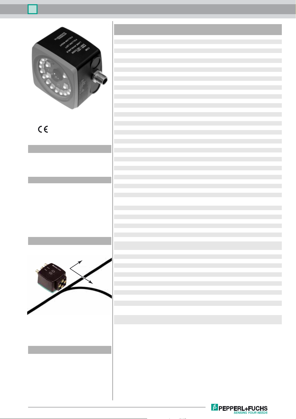
Read head for incident light positioning
system
Features
• RS-485 interface
• Mechanically rugged: no wearing
parts, long operating life,
maintenance-free
• Reading of Data Matrix control codes
• Infrared light
• Non-contact positioning on Data
Matrix code tape
Diagramms
Coordinates
X
Y
Light type Integrated LED lightning , infrared
Scan rate
Read distance 100 mm
Depth of focus ± 30 mm
Reading field 120 mm x 80 mm
Ambient light limit 100000 Lux
Resolution ± 0.2 mm
Nominal ratings
Camera
Type CMOS , Global shutter
Processor
Clock pulse frequency 600 MHz
Speed of computation 4800 MIPS
Functional safety related parameters
MTTFd 20 a
Mission Time (T
Diagnostic Coverage (DC) 0 %
Indicators/operating means
LED indicator 7 LEDs (communication, alignment aid, status information)
Electrical specifications
Operating voltage U
No-load supply current I
Power consumption P
Interface
Interface type RS 485 interface
Data output code binary code
Transfer rate 38400 ... 230400 Bit/s
Termination Switchable terminal resistor
Query cycle time ≥ 10 ms
Input
Input type 1 to 3 functional inputs , programmable
Input impedance ≥ 27 kΩ
Output
Output type 1 to 3 switch outputs , PNP , programmable , short-circuit
Switching voltage Operating voltage
Switching current 150 mA each output
Standard conformity
Emitted interference EN 61000-6-4:2007+A1:2011
Noise immunity EN 61000-6-2:2005
Shock resistance EN 60068-2-27:2009
Vibration resistance EN 60068-2-6:2008
Ambient conditions
Operating temperature 0 ... 60 °C (32 ... 140 °F) , -20 ... 60 °C (-4 ... 140 °F)
Storage temperature -20 ... 85 °C (-4 ... 185 °F)
Relative humidity 90 % , noncondensing
Mechanical specifications
Connection type 8-pin, M12 x 1 connector
Housing width 70 mm
Housing height 70 mm
Degree of protection IP67
Material
Housing PC/ABS
Mass approx. 160 g
) 10 a
M
B
0
0
-1
100 s
15 ... 30 V DC , PELV
max. 200 mA
3 W
protected
(noncondensing; prevent icing on the lens!)
System components
PGV*-CA25-*
Data Matrix code tape
PGV*-CC25-*
Control code tape für PGV System
PGV25M-CD100-CLEAR
Protective laminate for PGV code tape
Release date: 2016-09-12 11:48 Date of issue: 2018-06-05 285693-100003_eng.xml
Refer to “General Notes Relating to Pepperl+Fuchs Product Information”.
Approvals and certificates
UL approval cULus Listed, General Purpose, Class 2 Power Source,
CCC approval CCC approval / marking not required for products rated ≤36
Type 1 enclosure
V
1
PGV100SI-F200A-R4-V19Optical reading head
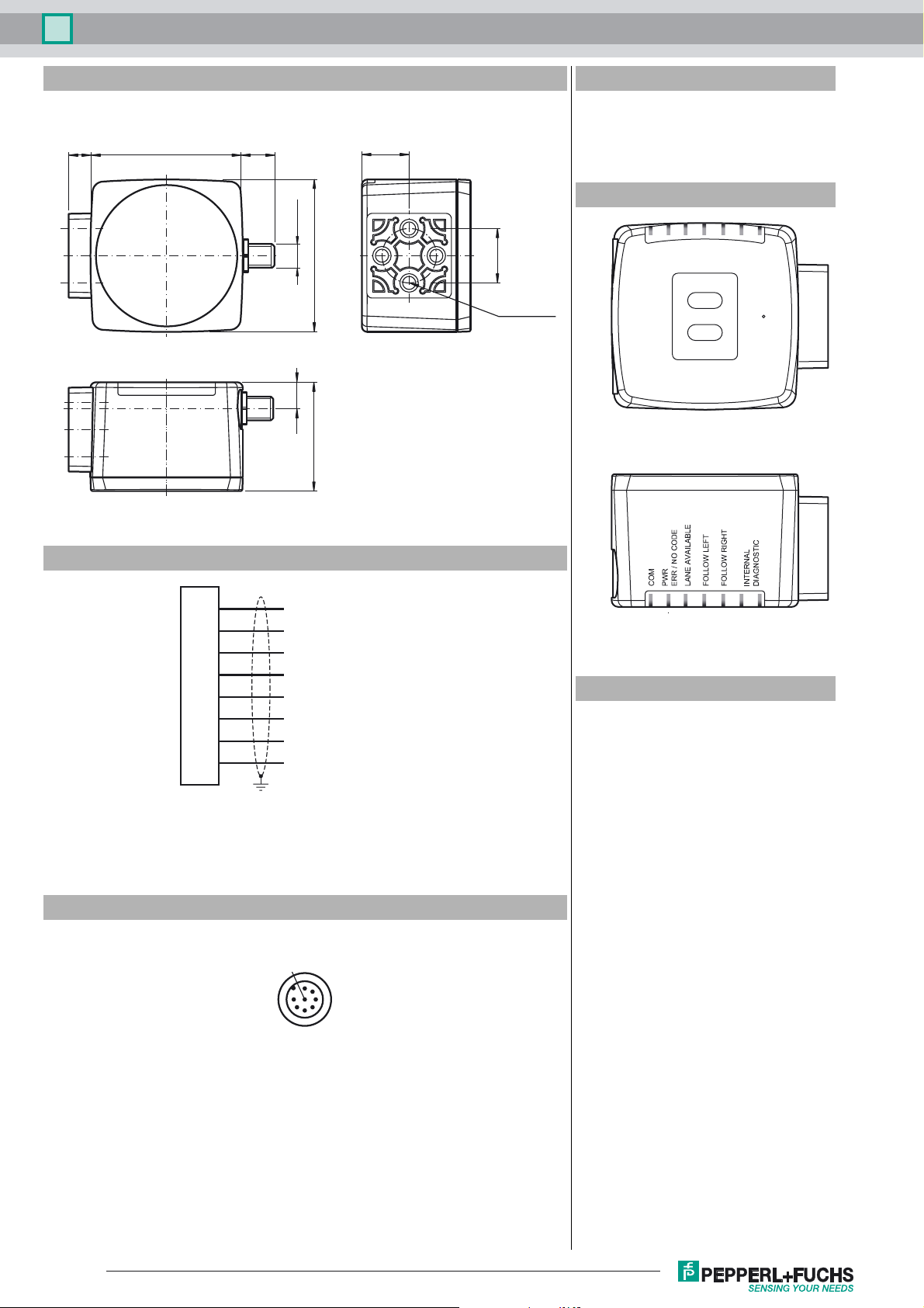
Dimensions
10 70 14.5
M12 x 1
70
12
50
System components
PGV85-CT4
Data matrix tag for PGV system
22
PGV25M-CD160-CLEAR
Protective laminate for PGV code tape
Additional information
ø 25
M6 x 9 (4x)
ADJUST
CONFIG
1
2
Electrical connection
1
2
3
4
5
6
7
8
OUT 2 / IN 2
+ UB
Data+ / TX / 485+
Data- / RX / 485-
OUT 1
IN 1
GND
OUT 3 / IN 3
Pinout
1
8
7
2
General
The PGV… reader forms part of the positioning system in the Pepperl+Fuchs incident light process. The reader's features include a camera module and an integrated illumination unit. The
reader uses these features to detect a colored strip stuck to the floor to track the lane. The reader also detects control codes and position markers in the form of Data Matrix codes attached
to a self-adhesive code tape. The code tape is usually mounted in a fixed position instead of
the colored strip or parallel to the colored strip. The reader is located on the front of an automated guided vehicle and guides this vehicle along the colored strip.
6
53
4
LED 1 2 3 4 5 6 7
Accessories
PCV-USB-RS485-Converter Set
USB to RS 485 interface converter
PCV-KBL-V19-STR-RS485
Cable unit with power supply for USB /
RS-485 interface converter
V19-G-ABG-PG9
Female connector, M12, 8-pin, shielded,
field attachable
V19-G-ABG-PG9-FE
Female connector, M12, 8-pin, shielded,
field attachable
PCV-SC12
Grounding clip for PCV system
PCV-AG100
Alignment guide for PCV100-* read head
PCV-LM25
Marker head for 25 mm code tape
PCV-MB1
Mounting bracket for PCV* read head
Vision Configurator
Operating software for camera-based
sensors
Release date: 2016-09-12 11:48 Date of issue: 2018-06-05 285693-100003_eng.xml
Refer to “General Notes Relating to Pepperl+Fuchs Product Information”.
2
Optical reading head PGV100SI-F200A-R4-V19
Mounting and Commissioning
Mount the reader such that the optical surface of the device captures the optimum reading distance to the colored strip (see "Technical Data"). The stability of the mounting and the manner
in which the vehicle is guided ensure that the reader is not operated outside of its depth of focus
range. The colored strip must not leave the maximum reading window for the reader during this
process.
All readers can be adapted to optimally meet specific requirements by means of parameterization.
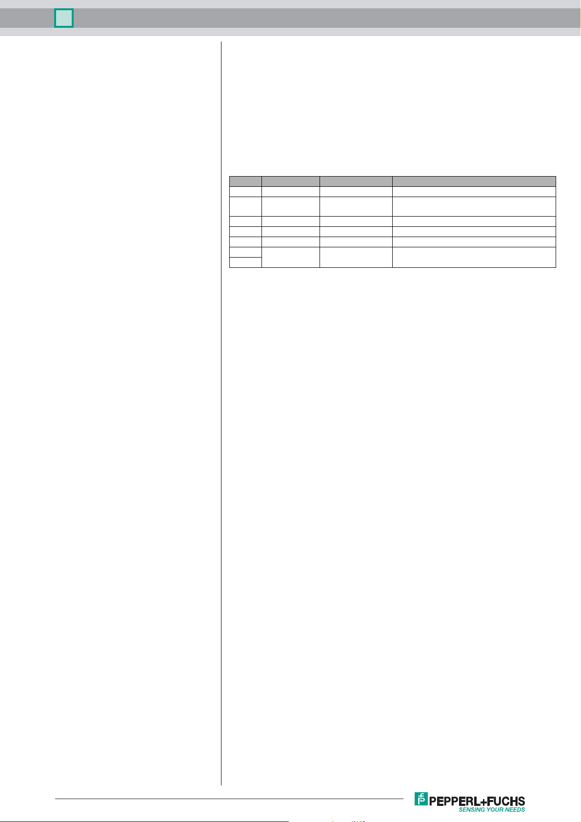
Indicators and Operating Controls
The PGV... reader is equipped with seven indicator LEDs for carrying out visual function
checks and rapid diagnostics. The reader is equipped with two buttons at the back for activating the alignment aid and parameterization mode.
LEDs
LED Color Label Meaning
1 Yellow COM Communication active
2 Green/red PWR
3 Yellow LANE AVAILABLE Lane available
4 Yellow FOLLOW LEFT "Follow left-hand lane" activated
5 Yellow FOLLOW RIGHT "Follow right-hand lane" activated
6 Red/green/yel7
low
ERR/NO CODE
INTERNAL
DIAGNOSTIC
External Parameterization
In order to parameterize the device externally, the parameterization code is required in the form
of a Data Matrix containing the desired reader parameters. Data Matrix code cards detailing
the step-by-step process for externally parameterizing the device are printed in the operating
instructions for the reader.
The reader can be parameterized only within ten minutes of being switched on. If a key is pressed after ten minutes of the device being switched on, a visual signal is given by the LEDs
(LED1, yellow/LED2, red/LED3, yellow/LED4, yellow/LED5, yellow, flashing for two seconds).
• The switchover from normal mode to parameterization mode is made by pressing button
2 on the back of the reader. To switch the device over, button 2 must be pressed and held
for more than two seconds. LED3 then flashes.
Note: Parameterization mode is exited automatically if the device is inactive for one
minute. In this case, the reader reverts to normal mode and operates without the settings
having been changed.
• Place the parameterization code in the field of vision of the camera module. After the parameterization code is detected, the green LED2 lights up for one second. In the event of
an invalid parameterization code, LED2 lights up red for two seconds.
• Briefly pressing button 2 will end parameterization mode.
Code detected/not detected, error
Internal diagnostics
Release date: 2016-09-12 11:48 Date of issue: 2018-06-05 285693-100003_eng.xml
Refer to “General Notes Relating to Pepperl+Fuchs Product Information”.
3
 Loading...