

Page 1
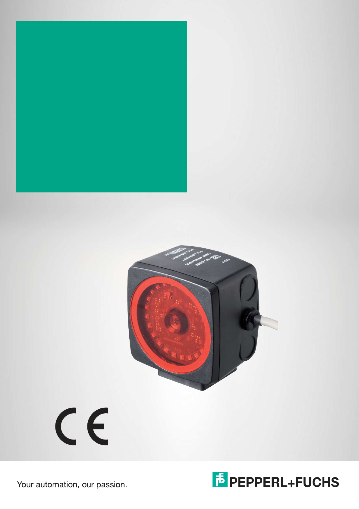
PGV100R-F200-R4-1.5M
Incident Light Positioning
System
Manual
Page 2

With regard to the supply of products, the current issue of the following document is applicable: The
General Terms of Delivery for Products and Services of the Electrical Industry, published by the Central
Association of the Electrical Industry (Zentralverband Elektrotechnik und Elektroindustrie (ZVEI) e.V.)
in its most recent version as well as the supplementary clause: "Expanded reservation of proprietorship"
Worldwide
Pepperl+Fuchs Group
Lilienthalstr. 200
68307 Mannheim
Germany
Phone: +49 621 776 - 0
E-mail: info@de.pepperl-fuchs.com
North American Headquarters
Pepperl+Fuchs Inc.
1600 Enterprise Parkway
Twinsburg, Ohio 44087
USA
Phone: +1 330 425-3555
E-mail: sales@us.pepperl-fuchs.com
Asia Headquarters
Pepperl+Fuchs Pte. Ltd.
P+F Building
18 Ayer Rajah Crescent
Singapore 139942
Phone: +65 6779-9091
E-mail: sales@sg.pepperl-fuchs.com
https://www.pepperl-fuchs.com
Page 3

PGV100R-F200-R4-1.5M
Contents
1 Introduction................................................................................................................ 5
1.1 Content of this Document............................................................................. 5
1.2 Target Group, Personnel ............................................................................... 5
1.3 Symbols Used ................................................................................................ 6
2 Product Description ..................................................................................................7
2.1 Use and Application ...................................................................................... 7
2.2 RS-485 Interface ............................................................................................ 9
2.3 LED Indicators and Operating Elements................................................... 10
2.4 Accessories.................................................................................................. 11
3 Installation................................................................................................................ 12
3.1 Mounting the Read Head............................................................................. 12
3.2 Affixing the Code Tape ................................................................................13
3.3 Electrical Connection .................................................................................. 23
4 Commissioning........................................................................................................ 25
4.1 Direction Decision ....................................................................................... 25
4.2 Parameterization Using Code Cards.......................................................... 26
4.2.1 The code cards "CANCEL", "USE", and "DEFAULT" ....................... 27
5 Operation and communication............................................................................... 28
5.1 Communication via the RS-485 Interface.................................................. 28
5.1.1 Request Telegram............................................................................ 28
5.1.2 Position Response Telegram............................................................ 29
5.1.2.1 Number of Lanes LC (Lane Count) ........................................................................................ 32
5.1.2.2 Orientation O .........................................................................................................................33
5.1.2.3 Side S .................................................................................................................................... 34
5.1.2.4 Position/Lane.........................................................................................................................34
5.1.3 Direction Decision Request Telegram .............................................. 35
5.2 Operation Using Control Codes .................................................................36
5.3 Operation Using Repair Tape...................................................................... 37
6 Appendix .................................................................................................................. 38
2020-09
3
Page 4

PGV100R-F200-R4-1.5M
Contents
6.1 Code Cards for External Parameterization................................................38
6.1.1 Code Cards with Special Functions.................................................. 38
6.1.2 Code Cards for Setting the Read Head Address .............................. 41
6.1.3 Code cards for setting the transfer rate ............................................ 43
6.1.4 Code Cards for Adjusting the Resolution.......................................... 45
6.1.5 Code cards for adjusting the terminator............................................ 46
2020-09
4
Page 5

PGV100R-F200-R4-1.5M
Introduction
1 Introduction
1.1 Content of this Document
This document contains information required to use the product in the relevant phases of the
product life cycle. This may include information on the following:
• Product identification
• Delivery, transport, and storage
• Mounting and installation
• Commissioning and operation
• Maintenance and repair
• Troubleshooting
• Dismounting
• Disposal
Note
For full information on the product, refer to the further documentation on the Internet at
www.pepperl-fuchs.com.
The documentation comprises the following parts:
• This document
• Datasheet
In addition, the documentation may comprise the following parts, if applicable:
• EU-type examination certificate
• EU declaration of conformity
• Attestation of conformity
• Certificates
• Control drawings
• Instruction manual
• Other documents
1.2 Target Group, Personnel
Responsibility for planning, assembly, commissioning, operation, maintenance, and dismounting lies with the plant operator.
Only appropriately trained and qualified personnel may carry out mounting, installation, commissioning, operation, maintenance, and dismounting of the product. The personnel must have
read and understood the instruction manual and the further documentation.
Prior to using the product make yourself familiar with it. Read the document carefully.
2020-09
5
Page 6
PGV100R-F200-R4-1.5M
Introduction
1.3 Symbols Used
This document contains symbols for the identification of warning messages and of informative
messages.
Warning Messages
You will find warning messages, whenever dangers may arise from your actions. It is mandatory
that you observe these warning messages for your personal safety and in order to avoid property damage.
Depending on the risk level, the warning messages are displayed in descending order as follows:
Danger!
This symbol indicates an imminent danger.
Non-observance will result in personal injury or death.
Warning!
This symbol indicates a possible fault or danger.
Non-observance may cause personal injury or serious property damage.
Caution!
This symbol indicates a possible fault.
Non-observance could interrupt the device and any connected systems and plants, or result in
their complete failure.
Informative Symbols
Note
This symbol brings important information to your attention.
Action
This symbol indicates a paragraph with instructions. You are prompted to perform an action or
a sequence of actions.
2020-09
6
Page 7
PGV100R-F200-R4-1.5M
Product Description
2 Product Description
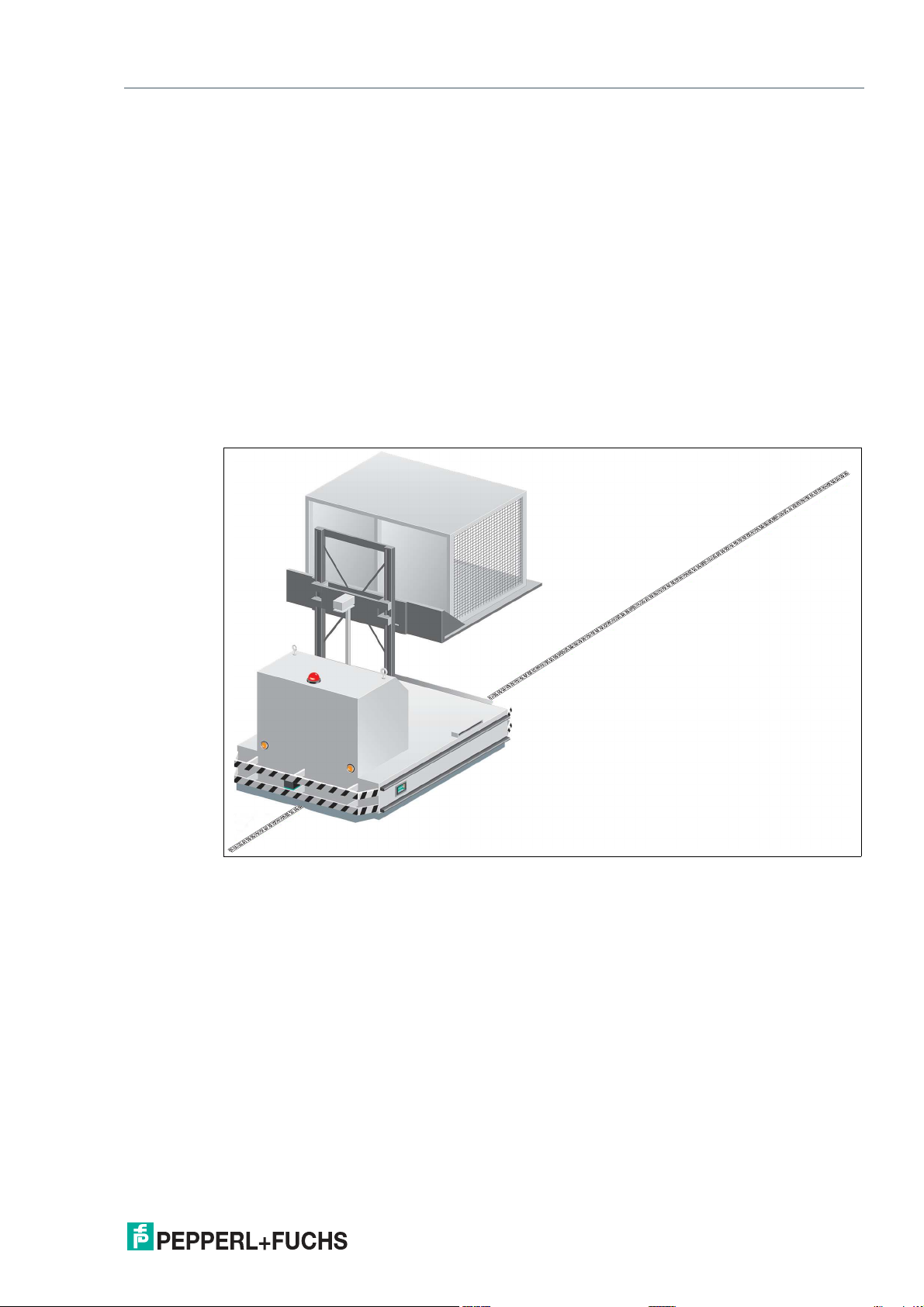
2.1 Use and Application
Intended Use
This device, when used together with a Data Matrix code tape affixed to the floor, constitutes a
high-resolution lane tracking and positioning system. It can be used in all applications where
auto-guided transport systems are to be positioned precisely at marked positions along a given
lane.
The read head forms part of the positioning system in the Pepperl+Fuchs incident light process. The read head includes a camera module and an internal illumination unit, which the read
head uses to detect a strip of Data Matrix code tape stuck to the floor for lane tracking and navigation. The read head also detects Data Matrix tags to navigate within a grid.
The read head is located on an auto-guided transport system and guides this system along the
Data Matrix code tape.
Figure 2.1 Auto-guided transport system with Data Matrix code tape
2020-09
7
Page 8
PGV100R-F200-R4-1.5M
Product Description
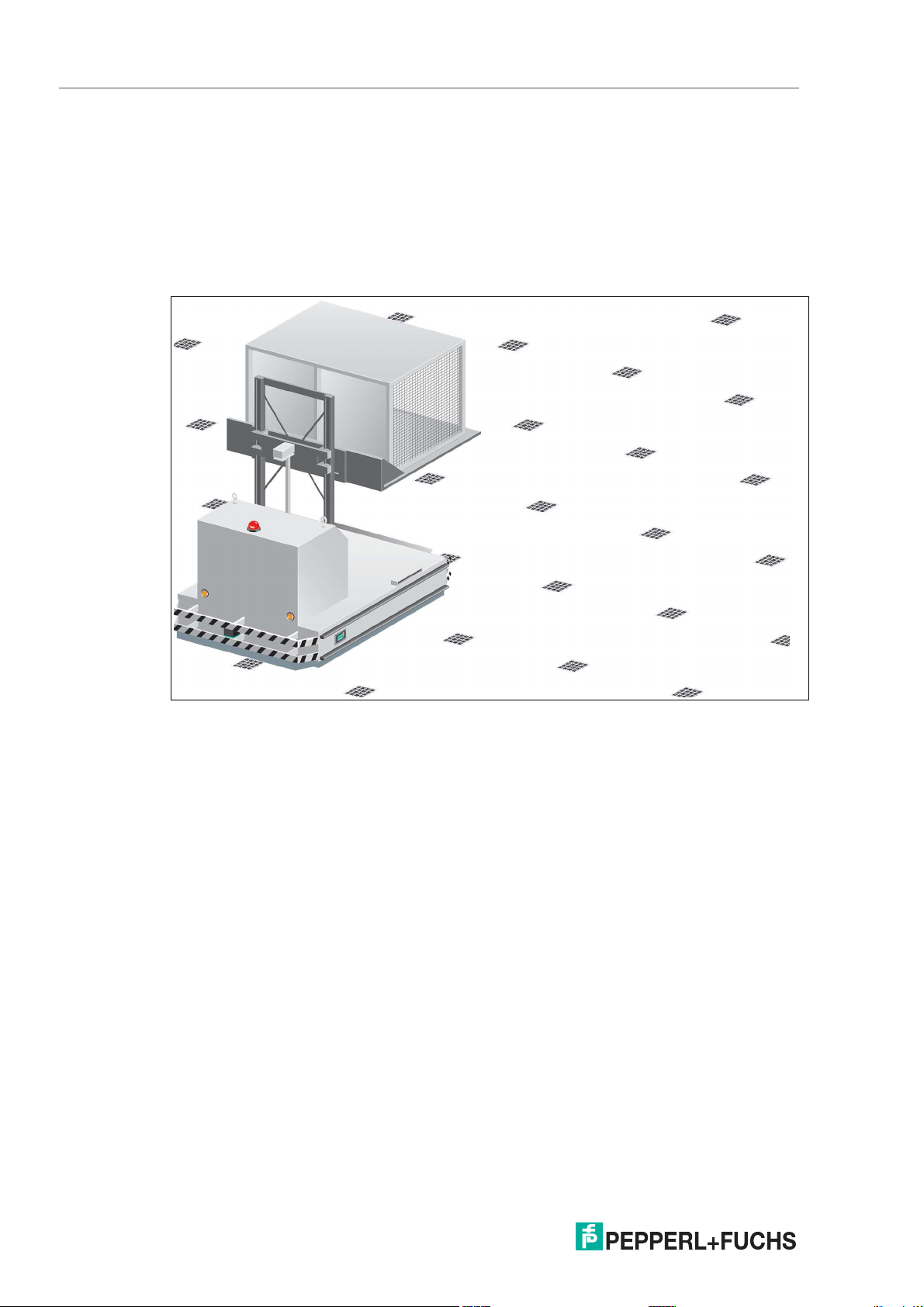
Tag Mode
In addition to lane tracking, the read head can also be used in tag mode. The read head detects
Data Matrix tags, which are typically glued onto the floor in a grid. The individual Data Matrix
tags are numbered consecutively and include position information. The read head reports the
position of the auto-guided transport system in relation to the zero point of the Data Matrix tag
to the control panel.
Tag mode allows the auto-guided transport system to move freely in as large a grid as desired,
without having to mark the traverse distances with code tapes.
Figure 2.2 Auto-guided transport system with Data Matrix tags
The read head switches automatically between tag mode and lane tracking. This allows a
transport system to be guided from one Data Matrix tag grid to another via a Data Matrix code
tape.
Thanks to its comprehensive and simple parameterization options, the read head can be optimally adapted to suit any application.
2020-09
8
Page 9
PGV100R-F200-R4-1.5M
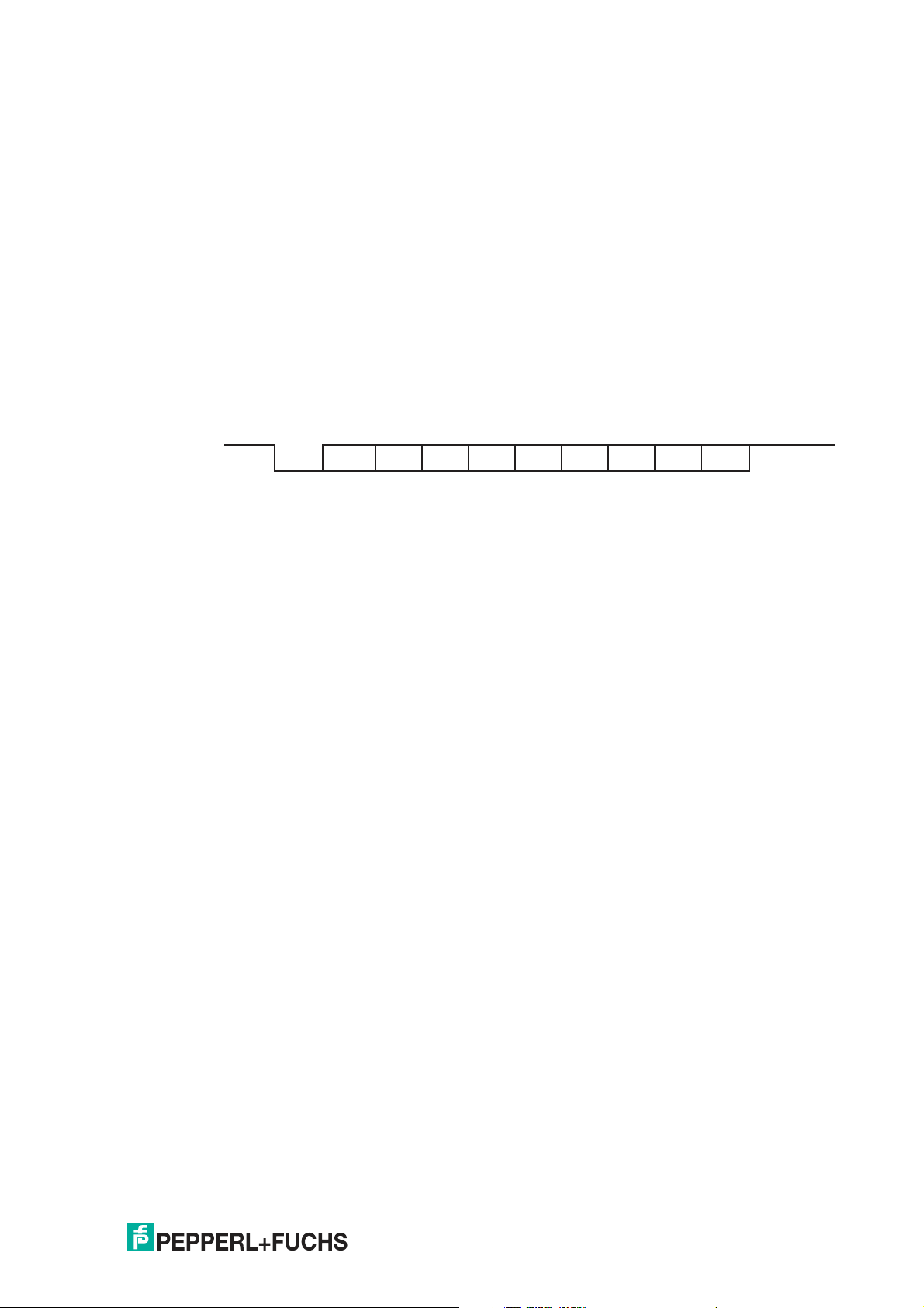
Bit 0
LSB MSBStart Stop
Bit 1 Bit 2 Bit 3 Bit 4 Bit 5 Bit 6 Bit 7 Parity
Product Description
2.2 RS-485 Interface
The read head is equipped with an RS-485 interface for communication purposes, i.e. parameterizing the read head functions or reading out current process data during operation. This
interface is operated in 8-E-1 operating mode and is fitted with a terminator that can be activated or deactivated by parameterizing the sensor head. The RS-485 interface supports the following transfer rates:
• 9600 bit/s
• 19200 bit/s
• 38400 bit/s
• 57600 bit/s
• 76800 bit/s
• 115200 bit/s (default value)
Data structure of the RS-485 interface
2020-09
9
Page 10
PGV100R-F200-R4-1.5M
ADJUST
COM STATE COM ERROR
POWER ON
NO CODE/
ERROR
CONFIG
1
2
Product Description
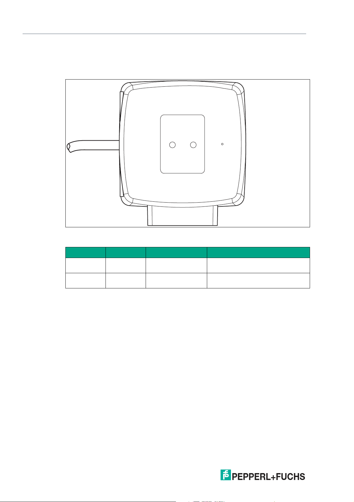
2.3 LED Indicators and Operating Elements
The read head is equipped with two indicator LEDs for carrying out visual function checks and
quick diagnostics.
Figure 2.3 Display elements
LEDs
LED Color Label Meaning
1 Green/yellow COM STATE
COM ERROR
2 Green/red POWER ON
RS-485 communication active
RS-485 communication error
Code detected/not detected, error
NO CODE/ ERROR
10
2020-09
Page 11
PGV100R-F200-R4-1.5M
Product Description
Function Indicator LED
LED 1 2
Mode COM STATE COM ERROR POWER ON
NO CODE/
ERROR
Color Green Yellow Green Red
Description
State Off Flashing x x General con-
figuration error
Off Off x x No communi-
cation
Table 2.1 f
= 2.5 Hz (one request line for flashing with three on statuses)
flash
x: LED status has no meaning
LED 1 2
NO CODE/
Mode COM STATE COM ERROR POWER ON
Color Green Yellow Green Red
ERROR
Description
State x x Lights up Off Codes
detected
x x Off Flashing Codes not
detected
x x x Lights up System error
x x Lights up for
1 s
x x Off Lights up for
Table 2.2 Sensor switched on: At least one of the LEDs is lit or flashing
x: LED status has no meaning
Off Code card
read
Code card not
1 s
read
2.4 Accessories
Compatible accessories offer enormous potential for cost savings. Such accessories not only
save you a great deal of time and effort during initial commissioning, but also when replacing
and maintaining our products.
If products are used in harsh ambient conditions, appropriate Pepperl+Fuchs accessories can
be used to extend the service life of these products.
Model number Description
PGV*-CA25-* Data Matrix code tape
PGV-CC25-0* Data Matrix control codes
PGV*M-CA25-* Data Matrix positioning tape
PGV85-CT4 Data Matrix tag
PGV25M-CD100-CLEAR Protective film
Table 2.3 Accessories
2020-09
11
Page 12
PGV100R-F200-R4-1.5M
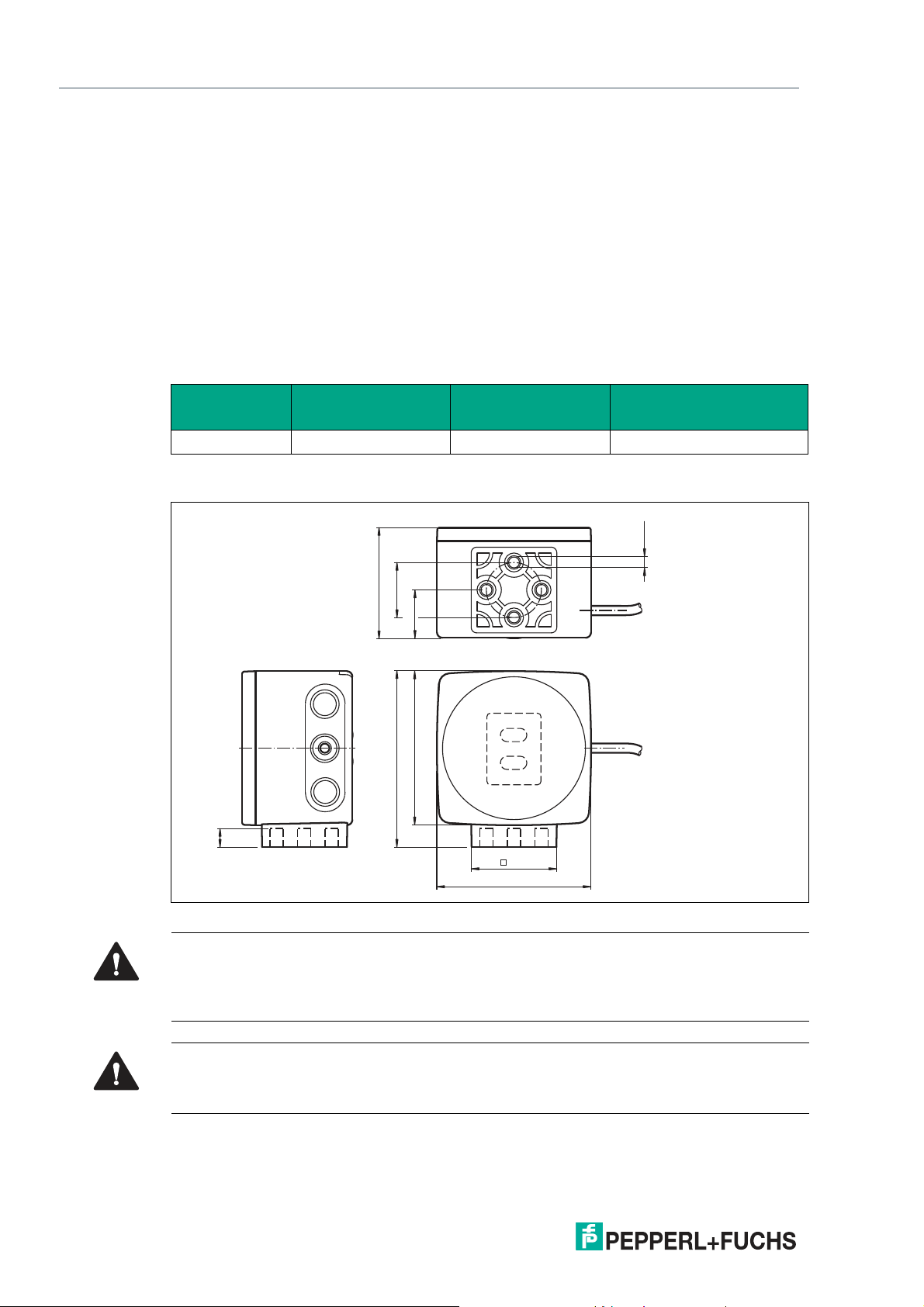
70
80
38.5
70
1
2
22
51
ø 25
9
4 x M6
Installation
3 Installation
3.1 Mounting the Read Head
Mount the read head on the auto-guided transport system using the four screws on the mounting adapter on the read head. Mount the read head so that the lens with ring light and camera
module are aligned toward the floor.
The mounting must be stable enough so that the read head does not leave its depth of focus
range during operation.
The distance between the read head and the floor should be the same as the read distance of
the read head.
Optimum Read Distance
Model number Read distance [mm] Depth of focus [mm]
PGV100R* 100 ±30 115 x 73
Field of vision (w x h)
[mm]
Read Head Dimensions
Figure 3.1 Housing dimensions
Caution!
When selecting the length of the mounting screws, ensure that the maximum insertion depth of
the screws in the threaded inserts on the read head is 8 mm.
Using longer screws may damage the read head.
Caution!
The maximum torque of the mounting screws must not exceed 9 Nm.
Tightening the screws to a higher torque may damage the read head.
2020-09
12
Page 13
PGV100R-F200-R4-1.5M
Installation
3.2 Affixing the Code Tape
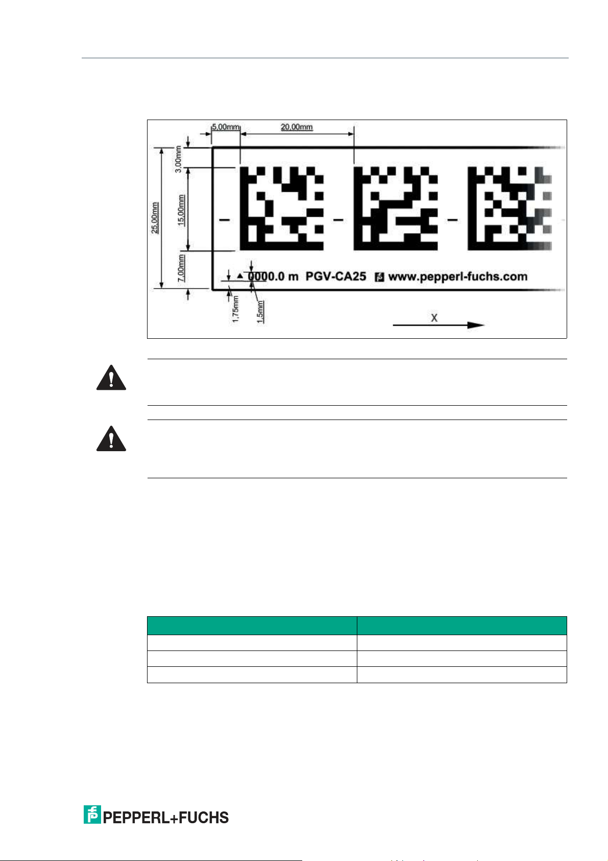
Dimensions of the Code Tape
Figure 3.2 Dimensions of the Data Matrix code tape
Caution!
Alignment
The Data Matrix code is not on the center line of the code tape.
Caution!
Stop edges
If you attach another code tape at the end of a previous code tape, the code pattern of 20 mm
must be retained.
The code tape is made of silicone-free polyester film. A position marker appears every 100 mm
along the lower edge of the code tape (see "Code Tape Dimensions"). These position markers
are used to affix the code tape in the correct position.
The back of the code tape is covered with a modified acrylate-based adhesive designed for
permanent adhesion. Affix the self-adhesive code tape along the desired traverse distance. To
do so, proceed as follows:
Position the code tape so that the www.pepperl-fuchs.com label and the position markings
are to the right of the Data Matrix code in the X direction. The position values then increase
along the X direction.
Data Matrix Code Tapes with a Starting Position of 0 m
Model number Description
PGV10M-CA25-0 Code tape, length: 10 m
... ...
PGV100M-CA25-0 Code tape, length: 100 m
Table 3.1 Data Matrix code tapes
See also data sheet PGV*-CA25-* at www.pepperl-fuchs.com
2020-09
13
Page 14
PGV100R-F200-R4-1.5M
Installation
Data Matrix Control Codes
Model number Description
PGV-CC25-001 Code tape, Control Code 001, length: 1 m
... ...
PGV-CC25-999 Code tape, Control Code 999, length: 1 m
Table 3.2 Data Matrix control codes
Affixing the Code Tape
1.
Clean the surface of any greasy or oily deposits and dust.
2.
Ensure that the surface is dry, clean, and stable.
3.
Pull away a few centimeters of the protective film at the beginning of the code tape. Place the
code tape at the precise point of the required starting position on the surface, and press to
attach.
4.
Then affix the code tape along the desired traverse distance. Please note the following
information:
5.
Remove the protective film gradually so that the code tape does not accidentally adhere to the
surface in an incorrect position. When affixing the code tape, ensure that it does not become
creased or trap air bubbles.
The adhesive on the code tape hardens after 72 hours.
Note
Thermal Expansion of the Code Tape
The affixed code tape corresponds to the heat expansion coefficient of the surface with regard
to its thermal expansion. Keep this in mind when installing expansion joints, for example.
Note
Expansion Joints and Code Tapes
If the system covers longer distances, the plant structure usually contains expansion joints. In
this case, we recommend creating breaks along the code tape. The resulting gap must not
exceed 75 mm.
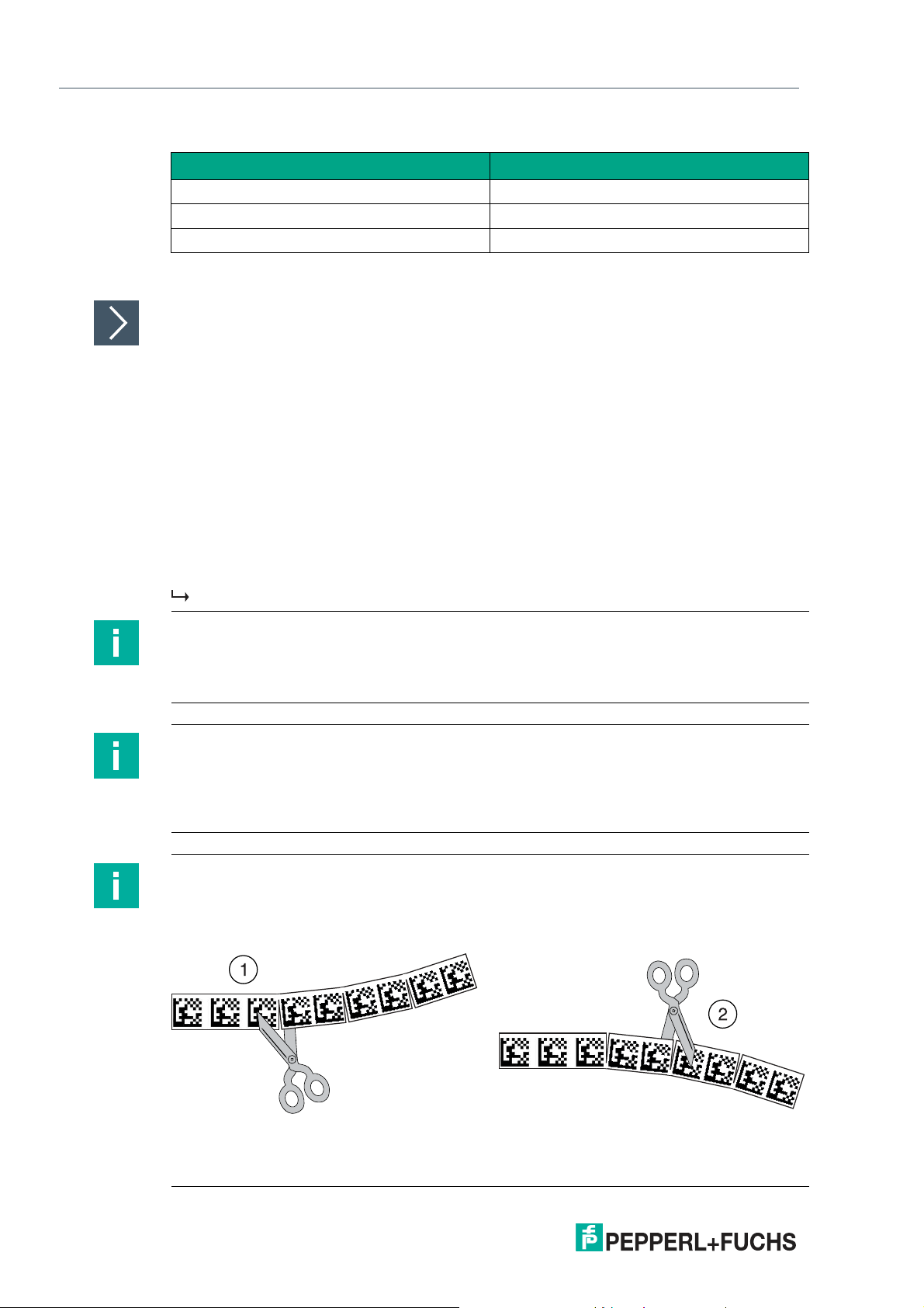
Note
Inclines and Declines
If you affix the code tape on inclines or declines, cut the code tape several times at the
transition point to the horizontal as shown.
14
Figure 3.3 Schematic diagram: preparing Data Matrix code tape bends
1. Bend to the left
2. Bend to the right
2020-09
Page 15
PGV100R-F200-R4-1.5M
X
Y
α
X
Y
α
Installation
Cleaning the Code Tape
Significant contamination on code tapes can impair detection by the read head. Clean the code
tapes with isopropanol if necessary. If the contamination is severe, you can use a non-corrosive
plastic cleaner, e.g., Caramba®.
Note
To avoid polishing the surface, do not apply strong pressure when cleaning. If the code tape
has a shiny surface, this impairs detection by the read head.
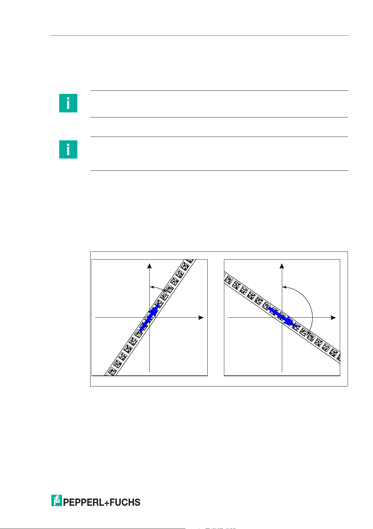
Angle Output
Note
Angles are specified as absolute values. The respective value is calculated from the resolution
selected under "Angle Resolution." With a resolution of 0.1°, an angle of 60° is output as
60°/0.1° = 600.
The read head detects the absolute angle in relation to the tracked lane with a maximum resolution of 0.1°. The angle is specified as an absolute value relative to the tracked lane, as a Data
Matrix code tape contains direction information. The output angle covers the range from 0° to
360°. The resolution can be set to the following values:
• 0.1°
• 0.2°
• 0.5°
• 1°
Figure 3.4 Absolute angle
2020-09
15
Page 16

PGV100R-F200-R4-1.5M
X
Y
A
Installation
Distance Output
The read head detects the distance from the zero point in the Y direction a Data Matrix code
tape and transmits this value to the control panel.
The reader indicates the vertical distance of the zero point in relation to the Data Matrix code
tape.
Figure 3.5 Distance A for Data Matrix code tape
Note
Direction Decision
The direction decision at a branch of a Data Matrix code tape remains in effect until the read
head has moved more than 50 cm away from the branch.
It is not possible to change the direction decision within a branch!
Note
Branches/Intersections with Data Matrix Position Code
Observe the following guidelines with regard to the area 1 m before and after branches or
intersections of a lane with a position code:
• The position codes of the main lane must run continuously for 2 m. The position codes of
the branching/intersecting lane must run continuously for 1 m. The read head outputs the
X-value of the Data Matrix code tape that is specified via the direction decision. .
• The difference between the absolute position of the main lane and the starting position of
the branching/intersecting lane must be greater than 1 m.
16
2020-09
Page 17

PGV100R-F200-R4-1.5M
1 m 1 m
1 m
Installation
Figure 3.6 Distances
2020-09
17
Page 18

PGV100R-F200-R4-1.5M
Installation
Behavior of the Read Head at Branches and Curves
The read head behaves differently depending on the type of branch and the specified lane. The
read head must know the upcoming direction decision.
A second lane branches off to the left from the straight lane:
The read head follows the straight lane if the direction decision "follow right-hand lane" has
been made.
A second lane branches off to the right from the straight lane:
The read head follows the straight lane if the direction decision "follow left-hand lane" has been
made.
A single lane with a position code turns to the left or right:
The read head follows the position code if the direction decision "straight ahead" has been
made.
Note
Loss of Information
Ensure that Data Matrix codes are not positioned over one another at a branch, as otherwise
data may be lost.
Control codes can be mounted in the immediate vicinity of a branch with Data Matrix codes for
positioning, but not near an intersection. The control code must be mounted directly next to the
guiding lane.
18
Figure 3.7 Branch with control code
2020-09
Page 19

PGV100R-F200-R4-1.5M
V
Installation
Distances
To ensure that the read head can clearly detect and assign Data Matrix codes, minimum and
maximum distances must be observed when creating the lanes.
Offset V between position codes of a lane must not be greater than 5 mm.
Figure 3.8 Offset: 0 mm V 5 mm
The distance between the Data Matrix code tapes at a branch or intersection as a separate lane
must be between 0 mm and 5 mm.
Figure 3.9 Distance: 0 mm D 5 mm
2020-09
19
Page 20

PGV100R-F200-R4-1.5M
25 mm D D 25 mm25 mm
Installation
The distance between a Data Matrix position code and a Data Matrix control code must be
between 0 mm and 5 mm.
Figure 3.10 0 mm D 5 mm
20
2020-09
Page 21

PGV100R-F200-R4-1.5M
+Y
-Y
www.pepperl-fuchs.com
TAG 12.345.678
42
54
TAG
1234.5678
55
54
44
45
4 5 1234 5678
=
5
85
85
Installation
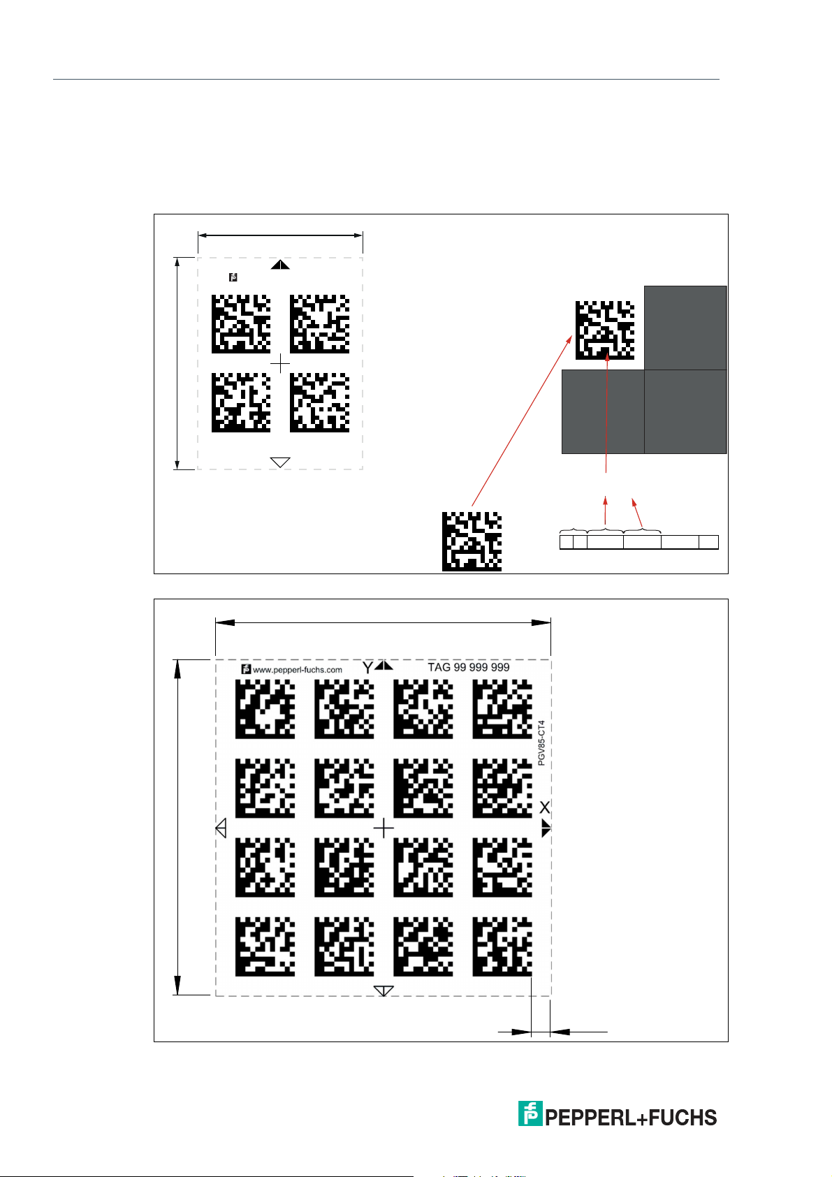
Data Matrix Tag (8 digit number)
A Data Matrix tag contains position information and a specific 8 digit number. A cross in the
center of the Data Matrix tag marks the zero point. The X and the Y axes are marked starting
from the zero point. The black arrow indicates the positive axis and the white arrow indicates
the negative axis.
Figure 3.11 2x2 Data Matrix tag with the number 123456789 and position information
2020-09
Figure 3.12 4x4 Data Matrix tag with the number 99999999 and position information
21
Page 22
PGV100R-F200-R4-1.5M
42
54
+Y
-Y
-X +X
www.pepperl-fuchs.com
TAG XX.XXX.XXX.XXX.XXX
TAG
1234.5678.9012.34
55
54
44
45
4 5 1234 5678=9012 34
5
85
85
Installation
Data Matrix Tag — Extended (14 digit number)
A Data Matrix tag contains position information and a specific 14 digit number. A cross in the
center of the Data Matrix tag marks the zero point. The X and the Y axes are marked starting
from the zero point. The black arrow indicates the positive axis and the white arrow indicates
the negative axis.
Figure 3.13 2x2 Data Matrix tag with number 12345678901234 and position information
22
Figure 3.14 4x4 Data Matrix tag with the number 99999999 and position information
2020-09
Page 23

PGV100R-F200-R4-1.5M
WH
BN
GN
YE
GY
PK
- UB
+ UB
n.c.
n.c.
DATA+
DATA-
PGV100 R
Installation
3.3 Electrical Connection
The read head is connected electrically via a fixed cable with open cores on the side of the
housing. The power is supplied via this connection. The configurable inputs and outputs on the
read head are also located at this connection.
Figure 3.15 Electrical connection
Color Assignment
Strand color Color abbreviation
White WH
Brown BN
Green GN
Yellow YE
Pink PK
Gray GY
Table 3.3 Color assignment
2020-09
23
Page 24

PGV100R-F200-R4-1.5M
Installation
Shielding Cables
The shielding of connection lines is required to suppress electromagnetic interference. Establishing a low resistance or low impedance connection with the protective conductor or equipotential bonding circuit is a particularly important factor in ensuring that these interference
currents do not become a source of interference themselves. Only use connection lines with
braid. Avoid connection lines with foil shield because this would increase the line capacities.
The shielding is integrated at both ends, i.e., in the switch cabinet or on the PLC, and on the
read head. The grounding terminal available as an accessory allows easy integration in the
equipotential bonding circuit.
In exceptional cases, the shielding of a connection at one end may be more favorable if:
• An equipotential bonding cable is not laid or cannot be laid.
• A film shield is used.
The following points relating to shielding must be noted:
• Use metal cable clips that cover large areas of the shielding.
• Place the cable shield onto the equipotential bonding rail immediately on entering the
switch cabinet.
• Direct the protective grounding connections to a common point in a star configuration.
• The cross-section of the cables used for grounding should be as large as possible.
Caution!
Damage to the device
Connecting an alternating current or excessive supply voltage can damage the device or cause
the device to malfunction.
Electrical connections with reversed polarity can damage the device or cause the device to
malfunction.
Connect the device to direct current (DC). Ensure that the supply voltage rating is within the
specified device range. Ensure that the connecting wires on the female cordset are connected
correctly.
24
2020-09
Page 25

PGV100R-F200-R4-1.5M
100
102
104
106
108
110
112
114
116
398
400
118
402
404
4
06
408
12
0
122
1
24
12
Commissioning
4 Commissioning
4.1 Direction Decision
The read head has several ways of following Data Matrix code tapes depending on the parameterization. Depending on the input signal, the read head follows the right-hand lane, the lefthand lane, or the better lane.
Direction Decision via Protocol
Direction control via the protocol.
Note
If direction decisions are made via the protocol, then subindex 12 "Input Source Selection"
must be switched to Software in the global primary data.
Following the Lane with More Detailed Position Information
You can parameterize the read head so that it follows the Data Matrix code tape that continues
the current location information.
Example
1. More detailed position information
2. New position information
2020-09
25
Page 26

PGV100R-F200-R4-1.5M
Commissioning
4.2 Parameterization Using Code Cards
During parameterization, the read head scans special code cards optically and configures the
relevant parameters. Simply hold the corresponding code cards at the correct distance in front
of the lens on the read head. The standard code cards are in the appendix.
Note
Parameterization mode can be activated in the first five minutes after voltage connection. A
time lock disables the read head once this time has elapsed. If parameterization is required at a
later time, switch off the supply voltage to the read head and switch it back on again.
Parameterization mode can now be activated within the first five minutes. The time lock
remains inactive during the parameterization process.
Activating Parameterization Mode
1.
To activate the read head, hold the "ACTIVATE" code card in the field of view of the read
head's camera system.
Note
The second parameterization code "USER" can be activated within the first
two minutes after the first parameterization code "ACTIVATE" has been
detected.
After recognition of the parameterization code, the activation of the parameterization mode
is enabled by the code card "USER". The read head can still be accessed by the controller.
2.
To activate the read head, hold the "USER" code card in the field of view of the read head's
camera system.
Once the parameterization code has been detected, LED2 lights up green for 1 second. The
read head is now in parameterization mode.
Completing Parameterization
Place the parameterization code in the field of view of the camera module.
Once the parameterization code has been detected, LED2 lights up green for 1 second.
If the parameterization code is invalid, LED2 lights up red for 1 second.
Exiting Parameterization Mode
Now hold the "STORE" code in front of the read head's camera system to save the configuration.
When the "STORE" memory code is detected, the LED2 lights up green for 1 second. The
parameterization is stored in the non-volatile memory of the read head and parameterization
mode is terminated. Parameterization of the read head is now complete. If the memory code is
not detected, LED2 lights up red for 1 second.
26
2020-09
Page 27

PGV100R-F200-R4-1.5M
Commissioning
4.2.1 The code cards "CANCEL", "USE", and "DEFAULT"
Holding one of these cards in front of the reading head exits parameterization mode with the
following consequences:
• CANCEL:
All parameter changes that are made but have not yet been saved are discarded. The
reading head operates with the last valid parameters that were saved.
• USE:
For test purposes, the reading head operates with the parameters that have just been
modified. The parameterization is not saved, however. After being switched off and on
again, the reading head operates with the last valid parameters that were saved.
• DEFAULT:
All parameters in the reading head are overwritten with the original default settings. Reenter the configuration mode and save the default settings nonvolatile with the code card
STORE.
2020-09
27
Page 28

PGV100R-F200-R4-1.5M
Operation and communication
5 Operation and communication
5.1 Communication via the RS-485 Interface
The controller and read head communicate via the RS-485 interface during operation. Make
sure that the basic communication settings have been made on the read head, such as setting
the read head address and baud rate.
A distinction is made between request telegrams that the controller sends to the read head and
response telegrams that the read head sends to the controller. Each byte of a request or
response telegram consists of 9 bits (8 data bits + 1 parity bit).
5.1.1 Request Telegram
A request telegram always consists of 2 bytes. The second byte corresponds to the first byte,
but with the 8 data bits of the first byte inverted.
Structure of a Request Telegram
Byte/
bit Bit 8 Bit 7 Bit 6 Bit 5 Bit 4 Bit 3 Bit 2 Bit 1 Bit 0 Function
1
Byte 1 Parity
Byte 2 Parity
Table 5.1 Structure of a request telegram
1
0 ~Req.
Req.
bit 4
bit 4
Req.
bit 3
~Req.
bit 3
Req.
bit 2
~Req.
bit 2
Req.
bit 1
~Req.
bit 1
Req.
bit 0
~Req.
bit 0
A1
~A1 ~A0 Checksum
A0 Request
1. R/W: 0 = response, 1 = request
Meaning of Bits
PAR R/W
Req.
bit 4
Req.
bit 3
Req.
bit 2
Req.
bit 1
Req.
bit 0 A1 A0 Function
Parity 1 x x x x x 0 0 Read head address 0
Parity 1 x x x x x 0 1 Read head address 1
Parity 1 x x x x x 1 0 Read head address 2
Parity 1 x x x x x 1 1 Read head address 3
Parity 1 1 0 0 1 0 x x Position inquiry
Parity 1 0 0 0 LL RL x x Selection of direction
Parity 1 1 0 R=0 G=0 B=1 x x Internal
Parity 1 0 0 R=0 G=1 B=0 x x Internal
Parity 1 0 0 R=1 G=0 B=0 x x Internal
Table 5.2 Meaning of bits
28
2020-09
Page 29

PGV100R-F200-R4-1.5M
Operation and communication
5.1.2 Position Response Telegram
A response telegram is 21 bytes long. Bytes 1 and 2 contain the read head address and status
information.
Response telegram from the read head — lane tracking
Bit 8 Bit 7 Bit 6 Bit 5 Bit 4 Bit 3 Bit 2 Bit 1 Bit 0
Byte 1
Byte 2
Byte 3
Byte 4
Byte 5
Byte 6
Byte 7
Byte 8
Byte 9
Byte 10
Byte 11
Byte 12
Byte 13
Byte 14
Byte 15
Byte 16
Byte 17
Byte 18
Byte 19
Byte 20
Byte 21
Table 5.3 Response telegram from the read head — lane tracking
Parity 0 CC2 A1 A0 CC1 WRN NP ERR
Parity 0
Parity 0 Reserved Reserved Reserved Reserved XPR23 XPR22 XPR21
Parity 0 XPR20 XPR19 XPR18 XPR17 XPR16 XPR15 XPR14
Parity 0 XPR13 XPR12 XPR11 XPR10 XPR09 XPR08 XPR07
Parity 0 XPR06 XPR05 XPR04 XPR03 XPR02 XPR01 XPR00
Parity 0 YPL13 YPL12 YPL11 YPL10 YPL09 YPL08 YPL07
Parity 0 YPL06 YPL05 YPL04 YPL03 YPL02 YPL01 YPL00
Parity 0 YPR_13 YPR_12 YPR_11 YPR_10 YPR_09 YPR_08 YPR_07
Parity 0 YPR_06 YPR_05 YPR_04 YPR_03 YPR_02 YPR_01 YPR_00
Parity 0 ANGL13 ANGL12 ANGL11 ANGL10 ANGL09 ANGL08 ANGL07
Parity 0 ANGL06 ANGL05 ANGL04 ANGL03 ANGL02 ANGL01 ANGL00
Parity 0 ANGL-
Parity 0 ANGL-
Parity 0 O1_1 O1_0 S1_1 S1_0 CC1_09 CC1_08 CC1_07
Parity 0 CC1_06 CC1_05 CC1_04 CC1_03 CC1_02 CC1_01 CC1_00
Parity 0 O2_1 O2_0 S2_1 S2_0 CC2_09 CC2_08 CC2_07
Parity 0 CC2_06 CC2_05 CC2_04 CC2_03 CC2_02 CC2_01 CC2_00
Parity 0 WRN13 WRN12 WRN11 WRN10 WRN09 WRN08 WRN07
Parity 0 WRN06 WRN05 WRN04 WRN03 WRN02 WRN01 WRN00
Parity 0 XOR
TAG [0]
R_13
R_06
B1.6
...
B20.6
1
LC1 LC0 RP NL LL RL
ANGR_12ANGR_11ANGR_10ANGR_09ANGR_08ANGR_0
ANGR_05ANGR_04ANGR_03ANGR_02ANGR_01ANGR_0
XOR
B1.5
...
B20.5
XOR
B1.4
...
B20.4
XOR
B1.3
...
B20.3
XOR
B1.2
...
B20.2
XOR
B1.1
...
B20.1
7
0
XOR
B1.0
...
B20.0
1. If bit = 0: read head follows the lane tape
2020-09
29
Page 30

PGV100R-F200-R4-1.5M
Operation and communication
Response telegram from the read head — Data Matrix tag
Bit 8 Bit 7 Bit 6 Bit 5 Bit 4 Bit 3 Bit 2 Bit 1 Bit 0
Byte 1
Byte 2
Byte 3
Byte 4
Byte 5
Byte 6
Byte 7
Byte 8
Byte 9
Byte 10
Byte 11
Byte 12
Byte 13
Byte 14
Byte 15
Byte 16
Byte 17
Byte 18
Byte 19
Byte 20
Byte 21
Table 5.4 Response telegram from the read head — Data Matrix tag
Parity 0 CC2 A1 A0 CC1 WRN NP ERR
Parity 0
Parity 0 Reserved Reserved Reserved Reserved XPL23 XPL22 XPL21
Parity 0 XPL20 XPL19 XPL18 XPL17 XPL16 XPL15 XPL14
Parity 0 XPL13 XPL12 XPL11 XPL10 XPL09 XPL08 XPL07
Parity 0 XPL06 XPL05 XPL04 XPL03 XPL02 XPL01 XPL00
Parity 0 YPL13 YPL12 YPL11 YPL10 YPL09 YPL08 YPL07
Parity 0 YPL06 YPL05 YPL04 YPL03 YPL02 YPL01 YPL00
Parity 0 TAG_55 TAG_54 TAG_53 TAG_52 TAG_51 TAG_50 TAG_49
Parity 0 TAG_48 TAG_47 TAG_46 TAG_45 TAG_44 TAG_43 TAG_42
Parity 0 ANGL13 ANGL12 ANGL11 ANGL10 ANGL09 ANGL08 ANGL07
Parity 0 ANGL06 ANGL05 ANGL04 ANGL03 ANGL02 ANGL01 ANGL00
Parity 0 TAG_41 TAG_40 TAG_39 TAG_38 TAG_37 TAG_36 TAG_35
Parity 0 TAG_34 TAG_33 TAG_32 TAG_31 TAG_30 TAG_29 TAG_28
Parity 0 TAG_27 TAG_26 TAG_25 TAG_24 TAG_23 TAG_22 TAG_21
Parity 0 TAG_20 TAG_19 TAG_18 TAG_17 TAG_16 TAG_15 TAG_14
Parity 0 TAG_13 TAG_12 TAG_11 TAG_10 TAG_09 TAG_08 TAG_07
Parity 0 TAG_06 TAG_05 TAG_04 TAG_03 TAG_02 TAG_01 TAG_00
Parity 0 WRN13 WRN12 WRN11 WRN10 WRN09 WRN08 WRN07
Parity 0 WRN06 WRN05 WRN04 WRN03 WRN02 WRN01 WRN00
Parity 0 XOR
TAG [1]
B1.6
...
B20.6
1
LC1 LC0 RP NL LL RL
XOR
B1.5
...
B20.5
XOR
B1.4
...
B20.4
XOR
B1.3
...
B20.3
XOR
B1.2
...
B20.2
XOR
B1.1
...
B20.1
XOR
B1.0
...
B20.0
1. If bit = 1: read head detects Data Matrix tag
2020-09
30
Page 31

PGV100R-F200-R4-1.5M
Operation and communication
Designation Function
A Address of the read head
ANGL Absolute angle of the left lane
ANGR Absolute angle of the right lane
CC1_#/CC2_#Control code 1 or 2 with number # detected
CC1/CC2 Associated control code is detected.
ERR Error message
LC Number of lanes in the reading window. Refer to section "Number of Lanes
LL/RL Selected direction decision
NL Internal
NP No absolute X position
O1_#/O2_# Orientation control code for lane. Refer to section "Orientation O"
S1_#/S2_# Relative position control code for lane. Refer to section "Side S."
RP Reserved
TAG Data Matrix tag detected
TAG_# Data Matrix tag with number # detected
WRN Warning message
XPL X position of left lane
XPR X position of right lane
YPL Y position of left lane
YPR Y position of right lane
Table 5.5 Functional description of the bits
Control code 2 is evaluated via the "Split value" function.
1
Error codes are stored in XP00 ... XP23. Additional information on the codes
can be found in the Error Codes table.
LC"
Warnings are stored in WRN00 ... WRN13. Additional information on the codes
can be found in the Warning Messages table.
1. Should you have any questions, please contact Pepperl+Fuchs
Error Codes
Error code Description Priority
2 No clear position can be determined, e.g., difference between
4
codes is too great, code distance incorrect
5 No direction decision available, , see chapter 5.1.3 2
6 Internal 3
> 1000 Internal error 1
Table 5.6 Error Codes
2020-09
31
Page 32

PGV100R-F200-R4-1.5M
Operation and communication
Warning Messages
Warning
message Description
WRN00 Code with content not typical of PGV found
WRN01 Read head too close to code tape
WRN02 Read head too far from code tape
WRN03 Reserved
WRN04 Reserved
WRN05 The read head is rotated or tipped in relation to the code tape
WRN06 Low level of code contrast
WRN07 Reserved
WRN08 Reserved
WRN09 Position code near branch/crossover detected
WRN10 More than the specified number of code lanes present
WRN11 Reserved
WRN12 Reserved
WRN13 Reserved
Table 5.7 If no warnings are present, the bits are set to 0.
Note
16 bit/32 bit
In order for the response telegrams from the read head to be transferred in 16 bit or 32 bit
values, fill in the missing bits as follows:
1. Unsigned: Fill in the missing upper bits with "0".
2. Signed: Fill in the missing upper bits with the highest bit of the response telegram.
Should you have any questions about this, please contact Pepperl+Fuchs.
5.1.2.1 Number of Lanes LC (Lane Count)
The lane count, LC, indicates the number of found Data Matrix lanes in the reading window. If
the lane count does not match the expected number of lanes, it may be due to the following
causes:
LC < actual number
• Lane is not located in the reading window
Meaning of Bits
LC1 LC0 Meaning
0 0 No lane found
0 1 1 lane found
1 0 2 lanes found
1 1 3 or more lanes found
32
2020-09
Page 33

PGV100R-F200-R4-1.5M
X
Y
O1=0
O0=0
O1=1
O0=0
O1=0
O0=1
O1=1
O0=1
Operation and communication
5.1.2.2 Orientation O
The orientation O indicates the orientation of the control codes in the reading window.
Meaning of Bits
O1 O0 Meaning
0 0 Control code has the same orientation as ascending Data Matrix lane
0 1 Orientation of control code rotated 90° clockwise in relation to ascending
1 0 Orientation of control code rotated 180° clockwise in relation to ascending
1 1 Orientation of control code rotated 270° clockwise in relation to ascending
Orientation
Data Matrix lane
Data Matrix lane
Data Matrix lane
Figure 5.1
2020-09
33
Page 34

PGV100R-F200-R4-1.5M
Operation and communication
5.1.2.3 Side S
Side S specifies the side of the Data Matrix lane on which the control codes are present.
Meaning of Bits
S1 S0 Meaning
0 0 No control code is present or found
0 1 Control code to the right of the Data Matrix lane
1 0 Control code to the left of the Data Matrix lane
1 1
Table 5.8 Meaning of bits S1 and S0
1. Control code laid on Data Matrix lane
No Data Matrix lane available
5.1.2.4 Position/Lane
You can use the following table to draw conclusions on the current section in the reading window based on the feedback from the read head regarding Data Matrix tag TAG, No Lane NL,
No X Position NP, absolute X position XP and the Y position and angle YPS/ANG.
Reserved
Not detectable
1
Meaning of Bits
TAG NL NP XP YPS/ANG Meaning
0 0 0
1
+
+ Data Matrix lane available. Position and angle
refer to the Data Matrix lane.
0 1 0 + + Data Matrix lane available.
0 1 1 - - No evaluable objects exist.
1 - 0 + + Position on the basis of a Data Matrix tag, X
position is signed.
Table 5.9 Meaning of bits
1. Valid data present
34
2020-09
Page 35

PGV100R-F200-R4-1.5M
Operation and communication
5.1.3 Direction Decision Request Telegram
Byte/
bit Bit 8 Bit 7 Bit 6 Bit 5 Bit 4 Bit 3 Bit 2 Bit 1 Bit 0 Function
Byte 1 Parity
Byte 2 Parity
Response Telegram for Direction Decision
Byte 1
Byte 2
Byte 3
Meaning of Bits
LL RL Meaning
0 0 Error code 5
0 1 Follow right-hand lane
1 0 Follow left-hand lane
1 1 Straight ahead
Table 5.10
1 1 1 0 LL RL
0 0 0 1 ~LL ~RL ~A1 ~A0 Checksum
Bit 8 Bit 7 Bit 6 Bit 5 Bit 4 Bit 3 Bit 2 Bit 1 Bit 0
Parity 0 CC2 A1 A0 CC1 WRN NP ERR
Parity 0 0 0 0 0 0 LL RL
Parity 0 XOR
B1.6
...
B2.6
XOR
B1.5
...
B2.5
XOR
B1.4
...
B2.4
XOR
B1.3
...
B2.3
A1
A0 Request
XOR
B1.2
...
B2.2
XOR
B1.1
...
B2.1
XOR
B1.0
...
B2.0
Example
Request telegram when read head address = 0
Request Response Description Example
0xE8, 0x17 See "Response Tele-
0xE4, 0x1B Follow right-hand lane --"0x01"--
gram for Direction
Decision"
Follow left-hand lane --"0x02"--
0xEC, 0x13 Straight ahead --"0x03"--
0xE0, 0x1F No lane is selected
--"0x00"--
Error code 5
2020-09
35
Page 36

PGV100R-F200-R4-1.5M
Operation and communication
5.2 Operation Using Control Codes
In numerous positioning system applications, defined processes (= event) must be started at
specific positions. This means that the exact positions must be defined via code tapes for positioning.
If an event needs to start at a particular position or a direction decision needs to be made, a
control code is mounted parallel to the actual lane.
Only a specific event and the associated process then have to be programmed into the plant
control system. The position in which the corresponding control code is placed next to the code
tape for positioning does not have to be determined until the point of final commissioning of the
plant. Even if subsequent changes are made to the layout of a plant, the relevant control code
is simply moved to the new position without the need for program modifications.
Control codes are short code tapes measuring one meter in length. The control code has an
encrypted number. Control codes have numbers ranging from 001 to 999.
When the read head enters the range of a control code, it sets the control code flag in its output
data.
The 1-meter-long control code can be shortened. However, the minimum length should be 3
codes (60 mm). If the speed of the read head increases, a longer control code is required. If the
read head travels at maximum speed, a full-length control code of 1 meter must be positioned
next to the code tape for positioning.
The minimum length of a control code can be calculated according to the following formula
depending on the travel speed and trigger period:
L
control code
The trigger period is 40 ms.
= 60 mm + V
[m/s] * T
max
Trigger
[s] x 2
Example
Example calculation
The minimum length of the control code at a speed of 3 m/s and a trigger period of 40 ms is:
L
Event marker
= 60 mm + 3 m/s * 40 ms * 2 = 300 mm
Control codes are identified by the printed number, in this case "Control 12".
Figure 5.2 PGV-CC25-0012
The illustration shows part of control code #12
Refer to the "Accessories" chapter for ordering information relating to control codes.
36
2020-09
Page 37

PGV100R-F200-R4-1.5M
Operation and communication
5.3 Operation Using Repair Tape
The repair tape is used to bridge defective or damaged areas of an existing code tape.
1.
Cut the repair tape to the required length
2.
Cover the defective area of the existing code tape with the repair tape
Note
When placing a repair tape on the code tape, make sure that the repair tape continues the
pattern on the code tape as accurately as possible.
Tip
If repairs are required, the Code Tape Generator at www.pepperl-fuchs.com can be used as a
short-term workaround. This generator enables segments of code tape to be produced and
printed out online.
Enter the start value in meters and the code tape length of the section to be replaced in meters.
This produces a printable PDF file containing the required segment of the code tape.
The printout must be used only as an emergency solution. The durability of the paper strip is
extremely limited depending on the application!
2020-09
37
Page 38

PGV100R-F200-R4-1.5M
Activate
Appendix
6 Appendix
6.1 Code Cards for External Parameterization
Here you will find the code cards that enable you to parameterize some of the basic functions
of the read head in a step-by-step process. For the exact external parameterization procedure
see chapter 4.2.
Note
When performing external parameterization with code cards, we recommend copying and
printing out the relevant pages in this manual and cutting out the required code cards. This
prevents the read head from mistakenly detecting another code card on the same page. If you
intend to use this manual directly for parameterization, cover the code cards that you do not
require with a sheet of paper, for example.
6.1.1 Code Cards with Special Functions
The following code cards have special functions:
• ACTIVATE
• USER
• STORE
• CANCEL
• USE
• DEFAULT
Activate
Figure 6.1 The "ACTIVATE" code card is used to activate external parameterization operating mode.
38
2020-09
Page 39

PGV100R-F200-R4-1.5M
User
Store
Cancel
Appendix
User
Figure 6.2 The "USER" code card is used to activate the user level in the external parameterization
Store
Figure 6.3 The "STORE" code card stores the modified parameterization in the nonvolatile memory of
Cancel
operating mode.
the read head and terminates external parameterization operating mode.
Figure 6.4 The "CANCEL" code card discards the modified parameterization and terminates external
2020-09
parameterization operating mode. The read head switches to normal mode and adopts the
last valid configuration that was saved.
39
Page 40

PGV100R-F200-R4-1.5M
Use
Default
Appendix
Use
Figure 6.5 The "USE" code card takes over the set configuration volatile in the read head working
Default
Figure 6.6 The "DEFAULT" code card restores the settings of the read head to default and terminates
memory and terminates the external parameterization operating mode. The read head then
operates with this configuration. However, if the read head is switched off and on again, the
configuration is lost and the read head operates with the last valid configuration that was
saved. This function is used primarily for test purposes.
external parameterization operating mode.
40
2020-09
Page 41

PGV100R-F200-R4-1.5M
Adresse 0
Adresse 1
Adresse 2
Appendix
6.1.2 Code Cards for Setting the Read Head Address
A unique address must be assigned to the read head so that it can be activated via the interface. The address range extends from 0 ... 3.
Read Head Address 0
Figure 6.7 The code card assigns address 0 to the read head.
Read Head Address 1
Figure 6.8 The code card assigns address 1 to the read head.
Read Head Address 2
Figure 6.9 The code card assigns address 2 to the read head.
2020-09
41
Page 42

PGV100R-F200-R4-1.5M
Adresse 3
Appendix
Read Head Address 3
Figure 6.10 The code card assigns address 3 to the read head.
42
2020-09
Page 43

PGV100R-F200-R4-1.5M
38400 Bit/s
57600 Bit/s
Appendix
6.1.3 Code cards for setting the transfer rate
Parameterization allows you to assign various transfer rates to the reading head for communication via the interface. The following transfer rates are available:
• 38400 bit/s
• 57600 bit/s
• 76800 bit/s
• 115200 bit/s
• 230400 bit/s
Transfer rate: 38400 bit/s
Figure 6.11 The transfer rate of the read head for communication via the interface is preset to 38400
Transfer rate: 57600 bit/s
Figure 6.12 The transfer rate of the read head for communication via the interface is preset to 57600
bit/s.
bit/s.
2020-09
43
Page 44

PGV100R-F200-R4-1.5M
76800 Bit/s
115200 Bit/s
230400 Bit/s
Appendix
Transfer rate: 76800 bit/s
Figure 6.13 The transfer rate of the read head for communication via the interface is preset to 76800
Transfer rate: 115200 bit/s
Figure 6.14 The transfer rate of the read head for communication via the interface is preset to 115200
Transfer rate: 230400 bit/s
bit/s.
bit/s.
44
Figure 6.15 The transfer rate of the read head for communication via the interface is preset to 230400
bit/s.
2020-09
Page 45

PGV100R-F200-R4-1.5M
Resolution
0.1 mm
Resolution
1 mm
Resolution
10 mm
Appendix
6.1.4 Code Cards for Adjusting the Resolution
Parameterization enables you to assign a position data resolution of 0.1 mm / 1 mm / 10 mm to
the read head.
Resolution: 0.1 mm
Figure 6.16 The code card assigns a position data resolution of 0.1 mm to the read head.
Resolution: 1 mm
Figure 6.17 The code card assigns a position data resolution of 1 mm to the read head.
Resolution: 10 mm
Figure 6.18 The code card assigns a position data resolution of 10 mm to the read head.
2020-09
45
Page 46

PGV100R-F200-R4-1.5M
Termination
off
Termination
on
Appendix
Maximum Length of the Code Tape
Resolution of the read head [mm] Maximum length of the code tape [km]
10 10
1 10
0.1 1,5
6.1.5 Code cards for adjusting the terminator
Parameterization enables you to switch a terminator on and off in the read head:
Terminator: OFF
Figure 6.19 The terminator is deactivated.
Terminator: ON
Figure 6.20 The terminator is connected.
46
2020-09
Page 47

Pepperl+Fuchs Qua lit y
Down load our latest poli cy he re:
www.pepperl-fuchs.com/quali ty
© Pepperl+Fuchs · Subject to modifications
www.pepperl-fuchs.com
Printed in Germany / DOCT-6492
 Loading...