

Page 1
PGV100-F200A-B25-V1D
Incident Light Positioning
System
Manual
Page 2

With regard to the supply of products, the current issue of the following document is applicable: The
General Terms of Delivery for Products and Services of the Electrical Industry, published by the Central
Association of the Electrical Industry (Zentralverband Elektrotechnik und Elektroindustrie (ZVEI) e.V.)
in its most recent version as well as the supplementary clause: "Expanded reservation of proprietorship"
Worldwide
Pepperl+Fuchs Group
Lilienthalstr. 200
68307 Mannheim
Germany
Phone: +49 621 776 - 0
E-mail: info@de.pepperl-fuchs.com
North American Headquarters
Pepperl+Fuchs Inc.
1600 Enterprise Parkway
Twinsburg, Ohio 44087
USA
Phone: +1 330 425-3555
E-mail: sales@us.pepperl-fuchs.com
Asia Headquarters
Pepperl+Fuchs Pte. Ltd.
P+F Building
18 Ayer Rajah Crescent
Singapore 139942
Phone: +65 6779-9091
E-mail: sales@sg.pepperl-fuchs.com
https://www.pepperl-fuchs.com
Page 3

PGV100-F200A-B25-V1D
Contents
1 Introduction................................................................................................................ 4
1.1 Content of this Document............................................................................. 4
1.2 Target Group, Personnel ............................................................................... 4
1.3 Symbols Used ................................................................................................ 5
2 Product Description ..................................................................................................6
2.1 Use and Application ...................................................................................... 6
2.2 LED Indicators and Operating Elements..................................................... 8
2.3 Accessories.................................................................................................... 9
3 Installation................................................................................................................ 10
3.1 Mounting the Read Head............................................................................. 10
3.2 Mounting the Colored Tape and Code Tape ..............................................12
3.3 Electrical connection................................................................................... 30
3.4 EtherNet/IP Connection .............................................................................. 32
4 Commissioning........................................................................................................ 33
4.1 Direction Decision ....................................................................................... 33
5 Communication via EtherNet/IP............................................................................. 36
5.1 General Information on Communication via EtherNet/IP ........................ 36
5.2 Setting the IP Address ................................................................................37
5.3 EtherNet/IP Objects .....................................................................................40
5.4 EtherNet/IP Connections ............................................................................ 43
5.5 Overview of the Attributes of EtherNet/IP Objects................................... 45
5.6 Description of the Attributes of EtherNet/IP Objects............................... 46
6 Appendix .................................................................................................................. 53
6.1 ASCII table.................................................................................................... 53
2020-12
3
Page 4

PGV100-F200A-B25-V1D
Introduction
1 Introduction
1.1 Content of this Document
This document contains information required to use the product in the relevant phases of the
product life cycle. This may include information on the following:
• Product identification
• Delivery, transport, and storage
• Mounting and installation
• Commissioning and operation
• Maintenance and repair
• Troubleshooting
• Dismounting
• Disposal
Note
For full information on the product, refer to the further documentation on the Internet at
www.pepperl-fuchs.com.
The documentation comprises the following parts:
• This document
• Datasheet
In addition, the documentation may comprise the following parts, if applicable:
• EU-type examination certificate
• EU declaration of conformity
• Attestation of conformity
• Certificates
• Control drawings
• Instruction manual
• Other documents
1.2 Target Group, Personnel
Responsibility for planning, assembly, commissioning, operation, maintenance, and dismounting lies with the plant operator.
Only appropriately trained and qualified personnel may carry out mounting, installation, commissioning, operation, maintenance, and dismounting of the product. The personnel must have
read and understood the instruction manual and the further documentation.
Prior to using the product make yourself familiar with it. Read the document carefully.
2020-12
4
Page 5
PGV100-F200A-B25-V1D
Introduction
1.3 Symbols Used
This document contains symbols for the identification of warning messages and of informative
messages.
Warning Messages
You will find warning messages, whenever dangers may arise from your actions. It is mandatory
that you observe these warning messages for your personal safety and in order to avoid property damage.
Depending on the risk level, the warning messages are displayed in descending order as follows:
Danger!
This symbol indicates an imminent danger.
Non-observance will result in personal injury or death.
Warning!
This symbol indicates a possible fault or danger.
Non-observance may cause personal injury or serious property damage.
Caution!
This symbol indicates a possible fault.
Non-observance could interrupt the device and any connected systems and plants, or result in
their complete failure.
Informative Symbols
Note
This symbol brings important information to your attention.
Action
This symbol indicates a paragraph with instructions. You are prompted to perform an action or
a sequence of actions.
2020-12
5
Page 6
PGV100-F200A-B25-V1D
Product Description
2 Product Description
2.1 Use and Application
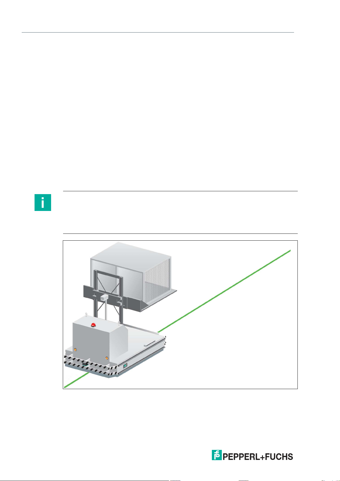
Intended Use
This device, when used together with a colored tape affixed to the floor and code tapes printed
with Data Matrix codes, constitute a high-resolution lane tracking and positioning system. It can
be used in all applications where automated guided vehicles (AGV) are to be positioned precisely at marked positions along a given lane.
The read head forms part of the positioning system in the Pepperl+Fuchs incident light process. The read head's features include a camera module and an integrated illumination unit.
The read head uses these features to detect a colored tape stuck to the floor or a painted color
lane to track the lane. The read head detects Data Matrix tags to navigate within a grid. The
read head also detects control codes and position markers in the form of Data Matrix codes
printed on a self-adhesive code tape. Data Matrix code tapes and Data Matrix tags have priority
over colored tapes or colored lanes.
The Data Matrix code tapes are installed in a fixed position instead of or along with the colored
tape. The read head is located on an automated guided vehicle (AGV) and guides this vehicle
along the colored tape.
Note
Priority
Data Matrix code tapes and Data Matrix tags have priority over colored tapes or colored lanes.
If the read head detects a Data Matrix code tape or Data Matrix tags in the field of view, colored
tapes or colored lanes in the field of view are ignored.
Figure 2.1 Automated guided vehicle with green colored tape
2020-12
6
Page 7
PGV100-F200A-B25-V1D
Product Description
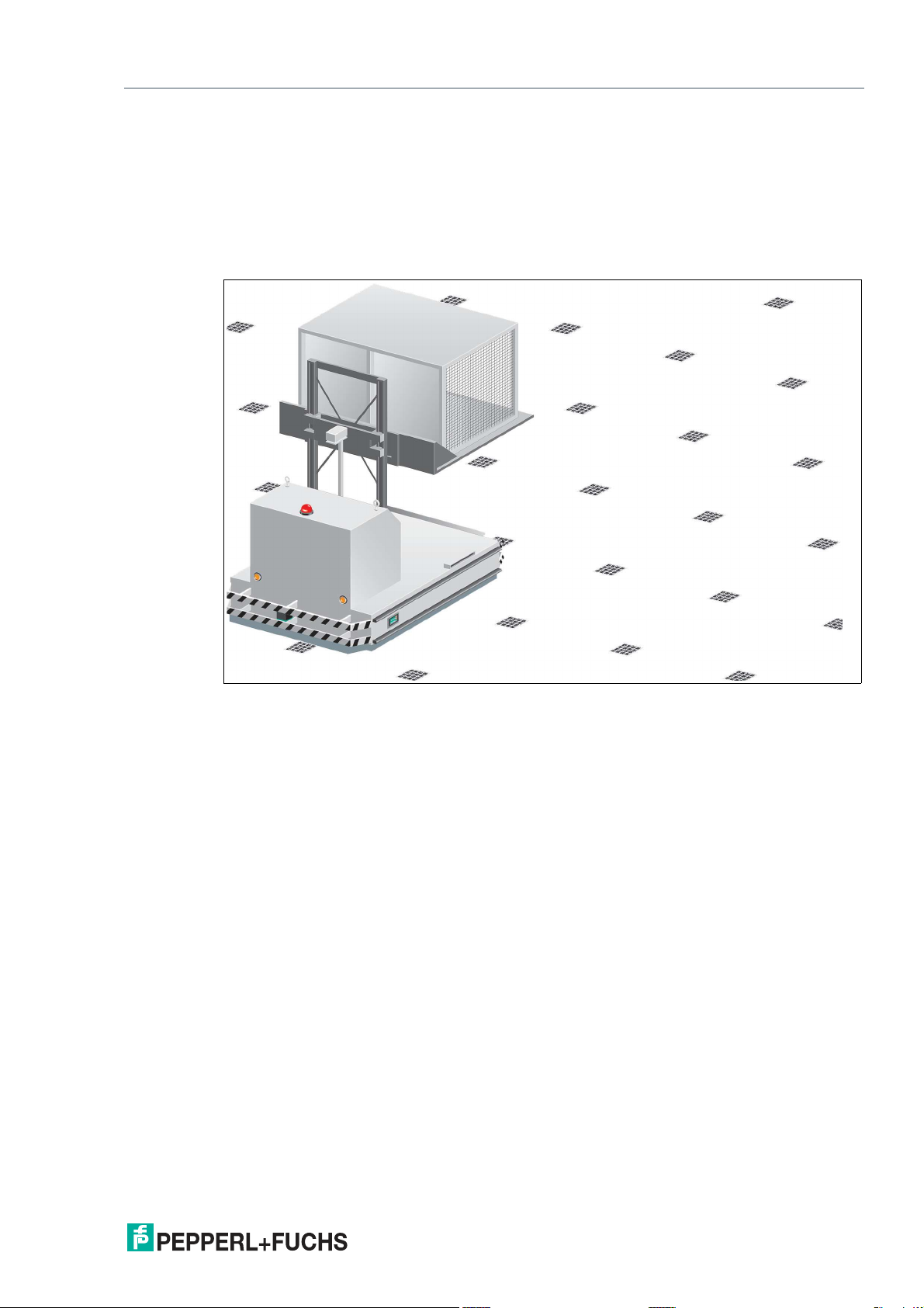
Tag Mode
In addition to the tracking, you can use the read head in tag mode. The read head detects Data
Matrix tags, which are typically glued onto the floor in a grid. The individual Data Matrix tags are
numbered consecutively and include position information. The read head reports the position
of the AGV in relation to the zero point of the Data Matrix tag to the controller.
The tag mode allows the AGV to move freely in as large a grid as desired, without having to
mark the crossing paths with lane tapes.
Figure 2.2 Automated guided vehicle with Data Matrix tags
The read head switches automatically between tag mode and lane tracking. This allows an
automated guided vehicle to be guided from one Data Matrix tag grid via a colored or Data
Matrix lane to another Data Matrix tag grid.
The extensive yet user-friendly parameterization options as well as the configurable inputs and
outputs mean that the read head can easily be adapted to suit each application.
2020-12
7
Page 8
PGV100-F200A-B25-V1D
ADJUST
CONFIG
1
2
LED 1 2 3 4 5 6 7
BUS ACTIVITY
Product Description
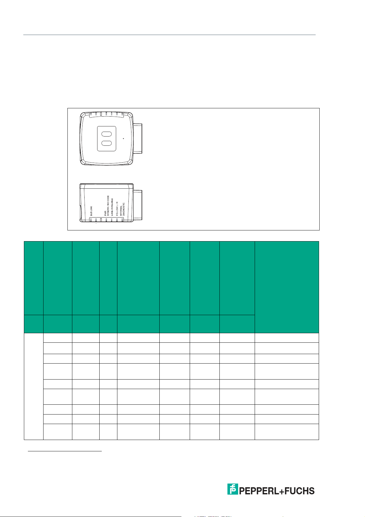
2.2 LED Indicators and Operating Elements
The read head has six indicator LEDs for carrying out visual function checks and quick diagnosis.
Activate the alignment aid and parameterization mode using the two control buttons on the
back of the device.
Button 1 is labeled "ADJUST." Button 2 is labeled "CONFIG."
Figure 2.3 Overview of LED indicators and controls
LED
[#1]
BUS LINK
[#2]
BUS ACTIVITY
Lights up x - x x x x Connection active
1
x
Flashing - x x x x Data transfer
x x - x x x x Communication errors
x x - x x x x No communication
x x - Lights up red x x x System error
x x - Lights up
x x - Off Flashing x x Code not detected
Table 2.1 Description of LED status
x x - x Lights up x x Tape detected
x x - x x Lights up x Direction selection
State
[#3]
No function
[#4]
PWR
SYSERR/NO CODE
[#5]
LANE AVAILABLE
[#6]
FOLLOW L/R
[#7]
INTERNAL DIAGNOSTIC
Red/green/
yellow
DescriptionColor Green Yellow - Green/red Yellow Yellow
error
x x x Code detected
green
active
1. x = LED status has no meaning
8
2020-12
Page 9

PGV100-F200A-B25-V1D
Product Description
Device switched on: at least one LED is switched on or flashing.
2.3 Accessories
Compatible accessories offer enormous potential for cost savings. Such accessories not only
save you a great deal of time and effort when commissioning for the first time, but also when
replacing and servicing our products.
If products are used in harsh ambient conditions, appropriate Pepperl+Fuchs accessories can
be used to extend the service life of these products.
Model number Description
V19-G-ABG-PG9-FE Grounding terminal and plug (set)
PCV-SC12 Grounding clip
V1SD-G-*M-PUR-ABG-V1SD-G Bus cable, M12 to M12, available in several
PCV-AG100 Alignment guide for reader
V19-G-*M-*
PCV-CM20-0* Event marker
PCV-MB1 Mounting bracket for reader
V19-G-*M-PUR-ABG Single-ended female cordset, M12, 8-pin,
PCV-LM25 Marker head for code tape
PGV33M-CB19-* PGV colored tape
PCV-KBL-V19-STR-USB USB cable unit with power supply
different lengths
Configurable connection cable
shielded, PUR cable
1
1. Ask your contact person at Pepperl+Fuchs
2020-12
9
Page 10

PGV100-F200A-B25-V1D
Installation
3 Installation
3.1 Mounting the Read Head
Mount the PGV... read head on the automated guided vehicle using the four screws on the
mounting adapter on the read head. Mount the read head in such a way that the lens with the
ring light and camera module are directed toward the colored tape.
The mounting must be stable enough so that the read head does not leave its depth of focus
range during operation.
The distance between the read head and the floor should be the same as the read distance of
the read head.
Optimal Read Distance
Model number Read distance [mm] Depth of focus [mm]
PGV100* 100 ± 20 117 x 75
Table 3.1 Read distance
Field of view (w x h)
[mm]
Hysteresis
If the read head has detected a colored tape, this colored tape can move in the Y direction from
the zero point within the viewing window. The maximum Y value at which the read head can still
capture this distance is designated as Y Value Out in the following table.
If the read head swivels onto a colored tape, the read head can capture the distance of the colored tape from the zero point only if the tape is less than a certain distance away from the zero
point. This distance is designated as Y Value In in the following table. The difference between
Y Value Out and Y Value In is the hysteresis. See "Distance Output" on page 16.
Model number Max. Y Value Out [mm] Min. Y Value In [mm]
PGV100* 60 45
Table 3.2 Distance to zero point
10
2020-12
Page 11
PGV100-F200A-B25-V1D
10 70 12
94.5
70
50
22
ø 25
M6 x 9 (4x)
12.5
20 20
Installation
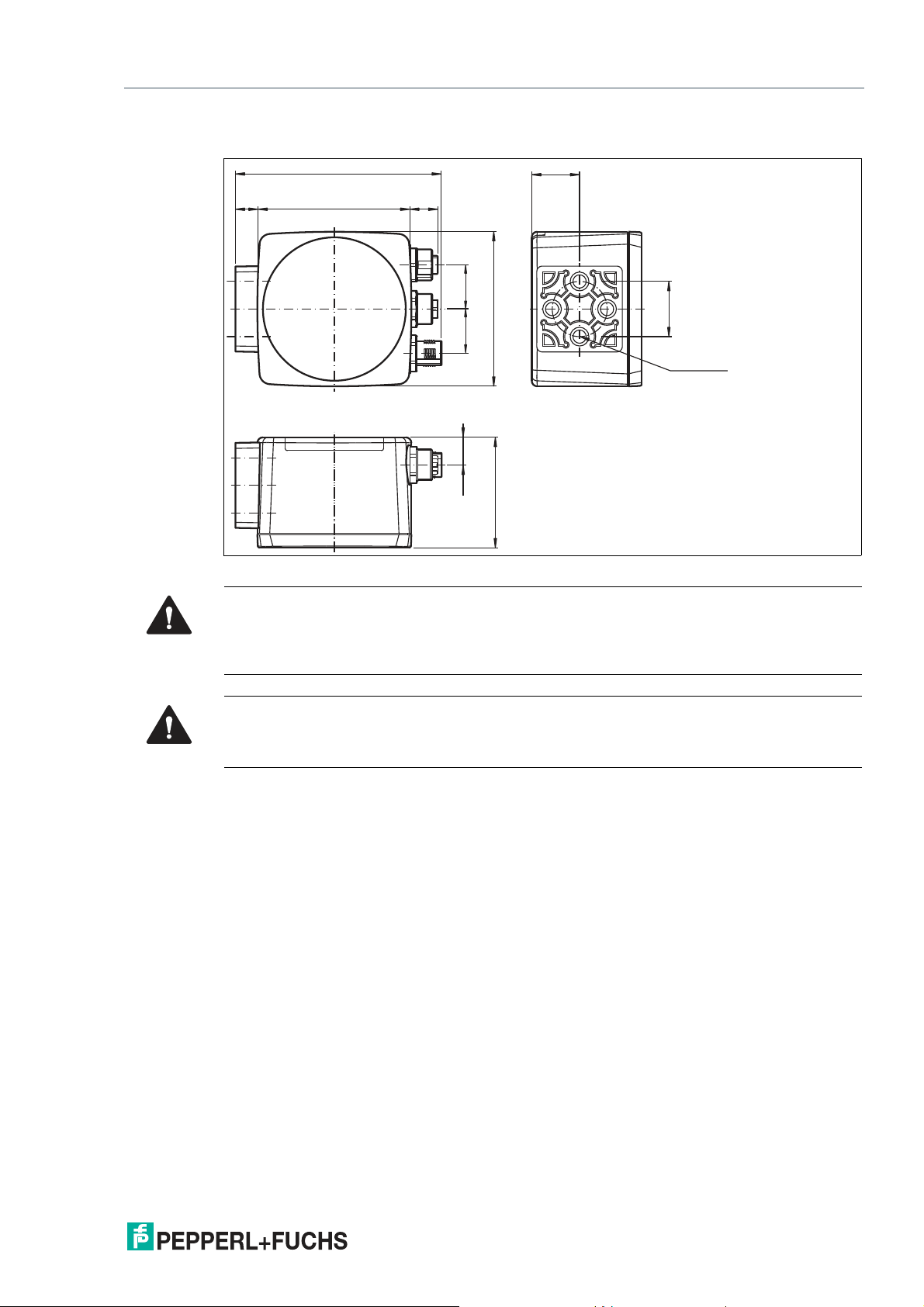
Read Head Dimensions
Figure 3.1 Dimensions
Caution!
When selecting the length of the mounting screws, ensure that the maximum insertion depth of
the screws in the threaded inserts on the read head is 8 mm.
Using longer screws may damage the read head.
Caution!
The maximum torque of the mounting screws must not exceed 9 Nm.
Tightening the screws to a higher torque may damage the read head.
2020-12
11
Page 12

PGV100-F200A-B25-V1D
Installation
3.2 Mounting the Colored Tape and Code Tape
Colored tape
The colored tape must be flexible, conformable, and resistant to abrasion, with a matte finish.
The colored tape must meet the following specifications:
• Tape width: 10 mm ... 40 mm
• Color of the tape
• Blue = RAL 5015
• Green = RAL 6032
• Red = RAL 3001
• Tape thickness > 0.1 mm
The thickness of the tape is irrelevant to read head operation.
• Breaking load > 25 N/cm
• Breaking elongation > 180%
• Adhesive strength > 2 N/cm
• Temperature resistance: -20 °C ... 70 °C
Secure the colored tape to the floor such that the following conditions are met:
• Data Matrix code tapes for positioning are used instead of the colored tape.
• Data Matrix control codes are positioned parallel to the colored tape.
Color Selection
Select the color of the colored tape so that the contrast between the floor color and the color of
the colored tape is as great as possible. Ideally, use the complementary color.
Due to the integrated lighting of the read head, some floor colors appear to be different in the
camera. If you have problems with the color selection of the colored tapes, please consult your
contact at Pepperl+Fuchs.
Mounting the Colored Tape
1.
Clean the surface of any greasy or oily deposits and dust.
2.
Ensure that the surface is dry, clean, and stable.
3.
Please observe the following section "Basics" when mounting the colored tape and, if
necessary, the instructions from the colored tape manufacturer.
Note
Priority
Data Matrix code tapes and Data Matrix tags have priority over colored tapes or colored lanes.
If the read head detects a Data Matrix code tape or Data Matrix tags in the field of view, colored
tapes or colored lanes in the field of view are ignored.
12
2020-12
Page 13
PGV100-F200A-B25-V1D
+Y
+X
+Z
R
Installation
Cleaning Colored Tape/Code Tape
Significant contamination on the colored or code tapes can impair the detection by the read
head. Clean the colored and code tapes with isopropanol if necessary. If the contamination is
severe, you can use a non-corrosive plastic cleaner, e.g., Caramba®.
Note
To avoid polishing the surface, do not apply strong pressure when cleaning. A shiny surface of
the colored or code tapes leads to impairment in detection by the read head.
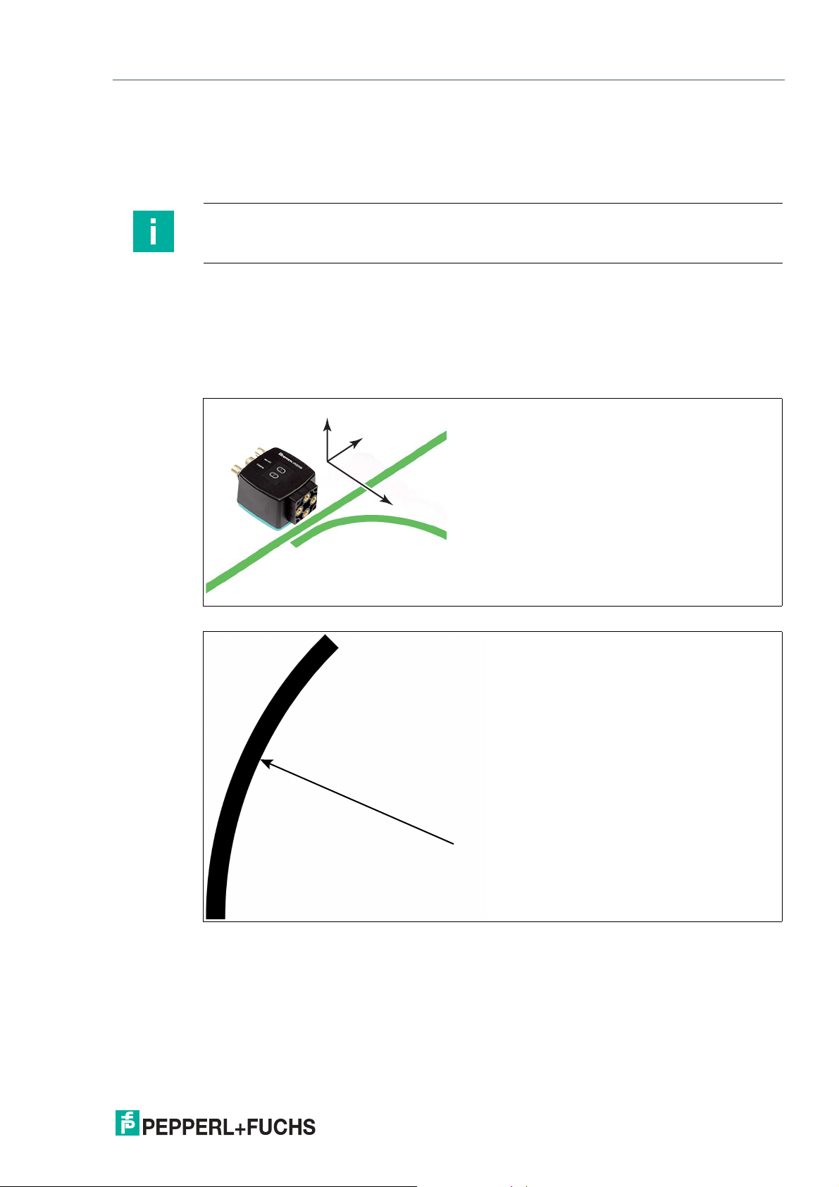
Basics
The read head detects a colored tape on a floor as a lane. The width of the colored tape must
be between 10 mm and 40 mm; the default width is 18 mm. The zero point is located in the center of the colored tape. You can use 3 defined colors. See the section entitled "Colored tape"
The sensor always moves in the X direction. In the sensor's field of view, X indicates an upward
movement.
Figure 3.2 Field of view and coordinates of the sensor
Figure 3.3 Curve radius: R 50 cm
Select a curve radius that can handle the turning circle of your automated guided vehicle.
The colored tape must always be located in the reading window of the read head.
2020-12
13
Page 14

PGV100-F200A-B25-V1D
X
Y
α
X
Y
α
β
✓
✗
Installation
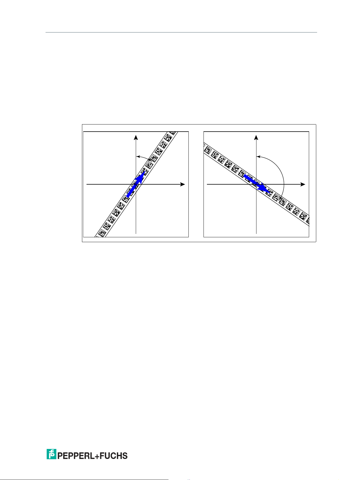
Angle Output
Note
Angles are specified as absolute values. The respective value is calculated from the resolution
selected under "Angle Resolution". With a resolution of 0.1°, an angle of 60° is output as
60°/0.1° = 600.
The read head detects a change of the angle of the colored tape and the Data Matrix code tape
and outputs this value to the controller. The output value is different for colored tapes and Data
Matrix code tapes.
Colored tape
The read head detects the angle in relation to the tracked lane with a resolution of 360 (corresponds to 1°). The angle is specified relative to the tracked lane because a colored tape does
not include any direction information. The output angle covers the range from -45° to 45°. The
resolution is 1°.
Figure 3.4 Relative angle
2020-12
14
Page 15
PGV100-F200A-B25-V1D
X
Y
α
X
Y
α
Installation
Data Matrix code tape
The read head detects the absolute angle in relation to the tracked lane with a maximum resolution of 0.1°. The angle is specified absolutely relative to the tracked lane, since a Data Matrix
code contains tape direction information. The output angle covers the range from 0° to 360°.
The resolution can be set to the following values:
• 0.1°
• 0.2°
• 0.5°
• 1°
Figure 3.5 Absolute angle
2020-12
15
Page 16
PGV100-F200A-B25-V1D
X
Y
A
Installation
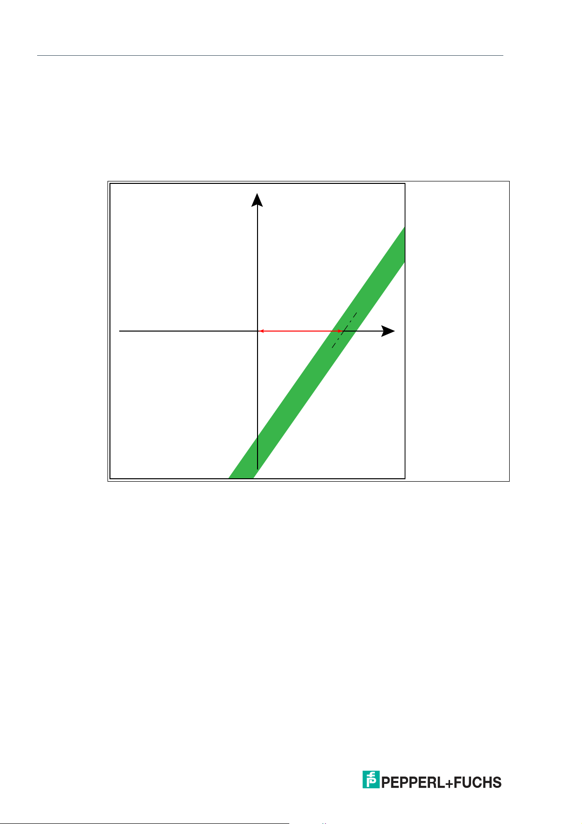
Distance Output
The read head detects the distance from the zero point in the Y direction of a colored tape or a
Data Matrix code tape and outputs this value to the controller. The output value is different for
colored tapes and Data Matrix code tapes due to the lack of an X position for colored tapes.
Colored tape
The read head outputs the Y value at which the colored tape intersects the Y axis as the distance.
Figure 3.6 Distance A for colored tape
2020-12
16
Page 17
PGV100-F200A-B25-V1D
X
Y
A
Installation
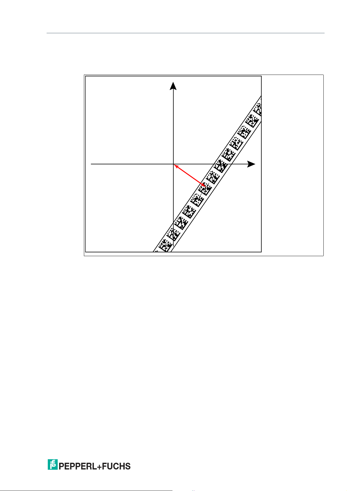
Data Matrix code tape
The read head indicates the vertical distance of the zero point in relation to the Data Matrix
code tape.
Figure 3.7 Distance A for Data Matrix code tape
2020-12
17
Page 18

PGV100-F200A-B25-V1D
Installation
Branches
The read head detects one lane at the lower edge of the field of vision and two lanes at the
upper edge of the field of vision; the read head indicates this as a branch.
The read head detects two lanes at the lower edge of the field of vision and one lane at the
upper edge of the field of vision; the read head indicates this as an intersection.
Branches or intersections can be displayed as follows:
Figure 3.8 Separate lane branches off/converges
The read head can make the following direction decisions based on the lane and possible
branches:
• Follow left-hand lane
• Straight ahead
• Follow right-hand lane
The direction decision is signaled to the read head via the controller. If there is no direction
decision, the read head displays an error message.
18
2020-12
Page 19

PGV100-F200A-B25-V1D
1
3
2
Installation
Code Tapes for Control and Positioning
In addition to tracking the lane, the read head can also detect Data Matrix codes. This process
involves evaluating both control and position information. Data Matrix control codes are used
as event markers. Control codes provide information on branches. Data Matrix code tapes for
positioning indicate the absolute position of the read head.
Note the following conditions:
Data Matrix code tapes for positioning are used instead of the colored tape.
Data Matrix control codes are used in tandem with the colored tape or Data Matrix position
code.
1 Colored tape
2 Data Matrix position code
3 Data Matrix control code
2020-12
19
Page 20

PGV100-F200A-B25-V1D
Installation
Branches or intersections with position information can be displayed as follows:
Figure 3.9 Separate lane branches off/converges
20
Figure 3.10 Same lane branches off/converges
2020-12
Page 21

PGV100-F200A-B25-V1D
1 m 1 m
1 m
Installation
Note
Direction Decision
The direction decision at a branch of a Data Matrix code tape remains in effect until the read
head has moved more than 50 cm from the branch.
It is not possible to change the direction decision within a branch!
Note
Priority
Data Matrix code tapes and Data Matrix tags have priority over colored tapes or colored lanes.
If the read head detects a Data Matrix code tape or Data Matrix tags in the field of view, colored
tapes or colored lanes in the field of view are ignored.
Note
Branches/Intersections with Data Matrix Position Code
Observe the following guidelines less than 1 m before and after branching or intersection of a
lane with a position code:
• The position codes of the main lane must run continuously for 2 m. The position codes of
the branching/intersecting lane must run continuously for 1 m. The read head outputs the
X-value of the Data Matrix code tape that is specified the direction decision. .
• Do not use repair tape.
• Do not use colored tape.
• The difference between the absolute position of the main lane and the starting position of
the branching/intersecting lane must be greater than 1 m.
Figure 3.11 Distances
2020-12
21
Page 22

PGV100-F200A-B25-V1D
Installation
Behavior of the Read Head at Branches and Corners
The read head behaves differently depending on the type of branch and the specified lane. The
read head must know the upcoming direction decision.
A second lane branches off to the left from the straight lane:
The read head follows the straight lane if the direction decision "follow right-hand lane" has
been made.
A second lane branches off to the right from the straight lane:
The read head follows the straight lane if the direction decision "follow left-hand lane" has been
made.
A single lane with a position code turns to the left or right:
The read head follows the position code if the direction decision "straight ahead" has been
made.
Note
Loss of Information
Ensure that Data Matrix codes are not positioned over one another at a branch, as otherwise
data may be lost.
It is not permitted to create a mixture of lanes made from colored tape and Data Matrix codes at
branches or intersections.
22
Figure 3.12 Mixture of lanes with colored tape and Data Matrix codes
2020-12
Page 23

PGV100-F200A-B25-V1D
Installation
Control codes can be mounted in the immediate vicinity of a branch with Data Matrix codes for
positioning, but not near an intersection. The control code must be mounted directly next to the
guiding lane.
Figure 3.13 Branch with control code
2020-12
23
Page 24

PGV100-F200A-B25-V1D
V
Installation
Distances
To ensure that the read head can clearly detect and assign colored tapes and Data Matrix
codes, minimum and maximum distances must be observed when creating the lanes.
Offset V between position codes of a lane must not be greater than 5 mm.
Figure 3.14 Offset: 0 mm V 5 mm
The distance D between the colored tapes at a branch or intersection as a separate lane must
not exceed 15 mm. The distance decreases if the guiding colored tape cannot be detected by
the read head in the center of the reading window.
24
Figure 3.15 Distance: 7.5 mm D 15 mm
2020-12
Page 25

PGV100-F200A-B25-V1D
25 mm D D 25 mm10...40 mm
Installation
The distance between the Data Matrix code tapes at a branch or intersection as a separate lane
must be between 0 mm and 5 mm.
Figure 3.16 Distance: 0 mm D 5 mm
The distance between a colored tape and a Data Matrix control code must be between 0 mm
and 5 mm.
Figure 3.17 0 mm D 5 mm
2020-12
25
Page 26

PGV100-F200A-B25-V1D
25 mm D D 25 mm25 mm
D
D
Installation
The distance between a Data Matrix position code and a Data Matrix control code must be
between 0 mm and 5 mm.
Figure 3.18 0 mm D 5 mm
A lane can switch from a colored tape to a Data Matrix code tape and back again as often as
required. The distance between the colored tape and the edge of the Data Matrix code must be
between 0 mm and 10 mm
26
Figure 3.19 0 mm D 10 mm
The Y value does not change if the colored tape and the Data Matrix code tape are aligned.
Ensure that the center line of the colored tape and the center line of the Data Matrix code are on
a line.
2020-12
Page 27

PGV100-F200A-B25-V1D
Installation
Caution!
Alignment
The Data Matrix code is not on the center line of the code tape.
The code tape is made of silicone-free polyester film. A position marker appears every 100 mm
along the lower edge of the code tape (see "Code Tape Dimensions"). This position marker is
used for various functions, including precise positioning of the code tape during installation.
The reverse side of the code tape carries a permanent modified acrylate-based adhesive. Affix
the self-adhesive code tape along the desired travel path. To do so, proceed as follows:
Installing the Code Tape
1.
Clean the surface of any greasy or oily deposits and dust.
2.
Ensure that the surface is dry, clean, and stable.
3.
Pull away a few centimeters of the protective film at the beginning of the code tape. Place the
code tape at the precise point of the required starting position on the surface, and press to
attach.
4.
Then affix the code tape along the desired travel path. Remove the protective film gradually so
that the code tape does not accidentally adhere to the surface in the incorrect position. When
affixing, ensure that the code tape does not crease or trap air bubbles.
The adhesive on the code tape hardens after 72 hours.
Note
Thermal Expansion of the Code Tape
The affixed code tape corresponds to the heat expansion coefficient of the surface with regard
to its thermal expansion.
Code Tape Dimensions
Figure 3.20 The center line indicates the center of the code tape and not the center of the code
Position the code tape so that the www.pepperl-fuchs.com label and the position markings
are to the right of the Data Matrix code in the X direction. The position values then increase
along the X direction.
2020-12
27
Page 28

PGV100-F200A-B25-V1D
Installation
Data Matrix Code Tapes with a Starting Position of 0 m
Order designation Description
PGV10M-CA25-0 Code tape, length: 10 m
... ...
PGV100M-CA25-0 Code tape, length: 100 m
Table 3.3 See also data sheet PGV*-CA25-* at www.pepperl-fuchs.com
Data Matrix control codes
Order designation Description
PGV-CC25-001 Code tape, Control Code 001, length: 1 m
... ...
PGV-CC25-999 Code tape, Control Code 999, length: 1 m
Caution!
Stop edges
If you attach another code tape at the end of a previous code tape, the code pattern of 20 mm
must be retained.
Note
Bends
If mounting the code tape in corners, cut the code tape several times as illustrated.
1 Bend to the left
2 Bend to the right
28
2020-12
Page 29

PGV100-F200A-B25-V1D
5
87
87
Installation
Data Matrix Tag
A Data Matrix tag contains position information in addition to a specific number. A cross in the
center of the Data Matrix tag marks the zero point. The X and the Y axes are marked starting
from the zero point. The black arrow indicates the positive axis and the white arrow indicates
the negative axis.
Figure 3.21 Data Matrix tag with the number 99999999 and position information
2020-12
29
Page 30

PGV100-F200A-B25-V1D
1
2
3
4
5
6
7
8
IN 2 / DIR LEFT
+ UB
n.c.
n.c.
OUT 1
IN 1 / DIR RIGHT
GND
OUT 3 / IN 3
Main
1
4
6
7
8
53
2
Main
Installation
3.3 Electrical connection
The read head is connected electrically via an 8-pin M12 x 1 connector plug on the side of the
housing. The voltage supply and communication with peripheral devices are established via
this connection. The configurable inputs and outputs on the read head are also located at this
connection.
Figure 3.22 Electrical connection of the read head
Plug Assignment
Figure 3.23 Plug assignment of the read head
Color assignment
Pepperl+Fuchs single-ended female cordsets are manufactured in accordance with EN609475-2. When using a type V19-... single-ended female cordset with an open cable end (see chapter 2.3) on the Main connection, the following color assignment applies:
Connection pin Core color Color abbreviation
1 White WH
2 Brown BN
3 Green GN
4 Yellow YE
5 Gray GY
6 Pink PK
7 Blue BU
8 Red RD
Table 3.4 Color assignment for connection to the single-ended female cordset
30
2020-12
Page 31

PGV100-F200A-B25-V1D
Installation
Shielding Cables
The shielding of connection lines is required to suppress electromagnetic interference. Establishing a low resistance or low impedance connection with the protective conductor or equipotential bonding circuit is a particularly important factor in ensuring that these interference
currents do not become a source of interference themselves. Only use connection lines with
braid. Avoid connection lines with foil shield because this would increase the line capacities.
The shielding is integrated at both ends, i.e., in the switch cabinet or on the PLC, and on the
read head. The grounding terminal available as an accessory allows easy integration in the
equipotential bonding circuit.
In exceptional cases, the shielding of a connection at one end may be more favorable if:
• An equipotential bonding cable is not laid or cannot be laid.
• A film shield is used.
The following points relating to shielding must be noted:
• Use metal cable clips that cover large areas of the shielding.
• Place the cable shield onto the equipotential bonding rail immediately on entering the
switch cabinet.
• Direct the protective grounding connections to a common point in a star configuration.
• The cross-section of the cables used for grounding should be as large as possible.
Additional Ground Connection
Tip
Using a short ground wire, establish grounding at the nearest ground connection.
Model number Description
PCV-SC12 Clip for mounting an additional ground con-
PCV-SC12A
Caution!
Damage to the device
Connecting an alternating current or excessive supply voltage can damage the device or cause
the device to malfunction.
Electrical connections with reversed polarity can damage the device or cause the device to
malfunction.
Connect the device to direct current (DC). Ensure that the supply voltage rating is within the
specified device range. Ensure that the connecting wires on the female cordset are connected
correctly.
nection.
2020-12
31
Page 32

PGV100-F200A-B25-V1D
1
2
3
4
TX +
RX +
TX -
RX -
Bus
EtherNet/IP 1 & 2
1
3
4
2
Installation
3.4 EtherNet/IP Connection
The read head is connected to EtherNet/IP via two 4-pin, D-coded connector sockets, M12 x 1,
port 1 and port 2, on the side of the housing.
Figure 3.24 EtherNet/IP electrical connection
Plug Assignment
Figure 3.25 Plug assignment for EtherNet/IP
Suitable Ethernet cables can be found in the Accessories section of the read head datasheet at
www.pepperl-fuchs.com.
32
2020-12
Page 33

PGV100-F200A-B25-V1D
t
1
0
1
0
INPUT_SELECTION_DIR_RIGHT
INPUT_SELECTION_DIR_LEFT
Direction decision
≥ 20 ms
Error 5 Left Error 5LeftRight
Commissioning
4 Commissioning
4.1 Direction Decision
The read head has several ways of following colored tapes and Data Matrix code tapes
depending on the parameterization. Depending on the input signal, the read head follows the
right-hand lane, the left-hand lane, or the better lane.
To ensure that the read head does not report any error messages after being switched on, a
direction decision must be specified. You can control the decision direction via inputs
INPUT_SELECTION_DIR_RIGHT (IN2/DIR_RIGHT) and INPUT_SELECTION_DIR_LEFT
(IN1/DIR_LEFT) or via the protocol. .
Direction Decision via Input Signal
Figure 4.1
Input 2
INPUT_SELECTION_DIR_LEFT
Input 1
INPUT_SELECTION_DIR_RIGHT Direction Decision
0 0 No lane is selected
Error code 5
0 1 Follow right-hand lane
1 0 Follow left-hand lane
1 1 Colored tape: follow lane with better quality
Data Matrix code tape: follow lane with more detailed
position information
Data Matrix tag: no significance
Table 4.1
Direction Decision via Protocol
Direction control via the protocol.
If direction decisions are made via the protocol, subindex 12 "Input source selection" must be
switched to "Software" in the global primary data.
Note
If direction decisions are sent to the read head via a protocol, the input signals from the
hardware input are ignored until the read head is reset. .
2020-12
33
Page 34

PGV100-F200A-B25-V1D
11 2 2
Commissioning
Following the Lane with Better Quality
You can parameterize the read head so that it follows the color lane with better quality.
Example
Figure 4.2 1 - Better color lane
2 - Worse color lane
34
2020-12
Page 35

PGV100-F200A-B25-V1D
100
102
104
106
108
110
112
114
116
398
400
118
402
404
4
06
408
120
122
124
12
Commissioning
Following the Lane with More Detailed Position Information
You can parameterize the read head so that it follows the Data Matrix code tape that has more
detailed current position information.
Example
Figure 4.3 1 - More detailed position information
2 - New position information
2020-12
35
Page 36

PGV100-F200A-B25-V1D
Communication via EtherNet/IP
5 Communication via EtherNet/IP
5.1 General Information on Communication via EtherNet/IP
The read head communicates with the controller (e.g., PLC) via EtherNet/IP. An object-oriented
fieldbus system for exchanging data between nodes based on Ethernet technology.
The management and development of the EtherNet/IP standards are subject to the Open DeviceNet Vendor Association (ODVA). More information on EtherNet/IP will be supplied on
request by the Open DeviceNet Vendor Association (ODVA) at the following Internet address:
ODVA, Inc
4220 Varsity Drive, Suite A
Ann Arbor, MI 48108-5006 USA
http://www.odva.org e-mail: mailto:odva@odva.org
The basic properties of the interface are:
• Transfer rate 10 Mbit/s or 100 Mbit/s, half or full duplex operation
• Automatic negotiation of the transfer rate and the duplex method (auto-negotiation)
• Automatic setting for crossed lines (auto-crossover)
EtherNet/IP protocol works according to the CIP protocol (Common Industrial Protocol) and is
used to control, configure, monitor, and collect data. Time-sensitive data exchange (implicit
messaging) takes place using the UDP/IP protocol and non-time-sensitive data exchange
(explicit messaging) using the TCP/IP protocol.
The read head supports the following features:
• "Listen only", "Input only", and "Exclusive Owner" connection types
• Message transmission as "Multipoint data transfer" (Multicast) and "Point-to-point data
transfer" (Unicast)
• Cycle time (request packet interval) 2 ms
• Dynamic Host Configuration Protocol (DHCP)
• Device Level Ring (DLR)
• Address Conflict Detection (ACD)
The read head is integrated in the network via a EDS file (electronic data sheet) with a configuration tool such as RSLOGIX5000. The EDS file contains all of the information about devicespecific parameters and operating modes.
Downloading the EDS file
You can find the relevant EDS file in the Software section of the product detail page for the
device.
To access the product detail page for the device, go to http://www.pepperl-fuchs.com and type
information about the device (e.g., the product description or the item number) into the search
function.
36
2020-12
Page 37

PGV100-F200A-B25-V1D
Communication via EtherNet/IP
5.2 Setting the IP Address
The read head is delivered in DHCP mode and waits for an address assignment from the control system.
The following section describes the address assignment via the software BOOT/DHCP server
from Rockwell Automation as an example.
1.
Connect the read head with the DHCP server.
2.
Start the BOOT/DHCP server software.
3.
Enter the following data in the Network Settings menu:
- Subnet Mask "255.255.255.0 "
- Gateway "192.168.1.1"
- the remaining fields are not filled in.
4.
Switch on the supply voltage to the read head.
2020-12
37
Page 38

PGV100-F200A-B25-V1D
Communication via EtherNet/IP
The read head cyclically carries out DHCP requests. This enters the MAC address of the
read head in the Request History field to the list.
5.
Enter the desired IP address in the New Entry menu.
- The software automatically adopts the MAC address of the read head.
- The "hostname" function is not supported.
- You may enter text under "Description".
6.
Confirm the entries of the address data using OK.
38
The IP address is assigned to the read head on the next DHCP request. The new address
data will be displayed in the Relation List field.
2020-12
Page 39

PGV100-F200A-B25-V1D
Communication via EtherNet/IP
7.
Press the Disable BOOTP/DHCP key in the Relation List field.
In this way, the assigned IP address is saved permanently in the read head.
2020-12
39
Page 40

PGV100-F200A-B25-V1D
Communication via EtherNet/IP
5.3 EtherNet/IP Objects
All the data and functions of the read head are defined via objects in accordance with the EtherNet/IP standards.
The read head supports the following listed standard-specific classes.
Standard Classes
Class ID Class description
0x01 Identity object
0x02 Message router object
0x04 Assembly object
0x06 Connection manager object
0xF5 TCP/IP interface object
0xF6 Ethernet link object
0x47 DLR object
0x48 Quality of service
The parameters are not directly addressable from the network with the "Set" or "Get" attribute
services. Access is via assembly objects (class code 0x04)
40
2020-12
Page 41

PGV100-F200A-B25-V1D
Communication via EtherNet/IP
Cyclic Data Communication with Assembly Objects (Class Code 0x04)
Assemblies are special CIP objects used for cyclic data communication (implicit messaging).
Assemblies are composed of one or more attributes of various objects. These objects allow you
to send or receive data from multiple objects via a connection. The composition of the assemblies is fixed in the read head and cannot be modified by the user.
Input Assemblies
Instance
no. Description
100 Status, Y position, angle 8 Status 100 UINT
101 Status, Y position, angle, warning,
102 Status, Y position, angle, X position, Z
103 Status, Y position, angle, X position, Z
104 Status, Y position, angle, X position,
105 Status, Y position, angle, X position,
2020-12
error
distance
distance, CCL status, CCL value,
warning, error
TAG number
TAG number, CCL status, CCL value,
warning, error
Size
[byte] Attribute
Y position 101 DINT
Angle 104 UINT
12 Status 100 UINT
Y position 101 DINT
Angle 104 UINT
Warning 102 UINT
Error 103 UINT
14 Status 100 UINT
Y position 101 DINT
Angle 104 UINT
X position 105 UDINT
Z distance 106 UINT
21 Status 100 UINT
Y position 101 DINT
Angle 104 UINT
X position 105 UDINT
Z distance 106 UINT
CCL status 107 USINT
CCL value 108 UINT
Warning 102 UINT
Error 103 UINT
16 Status 100 UINT
Y position 101 DINT
Angle 104 UINT
X position 105 UDINT
Tag value 109 UDINT
23 Status 100 UINT
Y position 101 DINT
Angle 104 UINT
X position 105 UDINT
Tag value 109 UDINT
CCL status 107 USINT
CCL value 108 UINT
Warning 102 UINT
Error 103 UINT
Attribute
ID Data type
41
Page 42

PGV100-F200A-B25-V1D
Communication via EtherNet/IP
Instance
no. Description
106 CCL status, CCL value 3 CCL status 107 USINT
107 Warning, error 4 Warning 102 UINT
108 Status, Y position, angle, X position, Z
Configuration assembly
Instance
no. Description
110 Configuration 58 X resolution 110 UDINT
distance, TAG number, CCL status,
CCL value, warning, error
Size
[byte] Attribute Attribute ID Data type
Y resolution 111 UDINT
Angle resolution 112 DINT
Horizontal offset 113 DINT
Vertical offset 114 INT
Angle offset 115 DINT
No position X 116 UDINT
No position X value 117 UDINT
No position Y 118 UDINT
No position Y value 119 DINT
No position angle 120 UDINT
No position angle value 121 UDINT
Color tape width 122 UDINT
Color 123 UDINT
Input source selection 124 UDINT
Size
[byte] Attribute
CCL value 108 UINT
Error 103 UINT
25 Status 100 UINT
Y position 101 DINT
Angle 104 UINT
X position 105 UDINT
Z distance 106 UINT
Tag value 109 UDINT
CCL status 107 USINT
CCL value 108 UINT
Warning 102 UINT
Error 103 UINT
Attribute
ID Data type
42
Output assembly
Instance no. Description Size [byte] Attribute Attribute ID Data type
115 Output 1 Steering infor-
mation
125 BYTE
2020-12
Page 43

PGV100-F200A-B25-V1D
Communication via EtherNet/IP
5.4 EtherNet/IP Connections
No. Type Parameter
1 Exclusive
owner
2 Input only Status, Y position, angle 115 100 110
3 Listen only Status, Y position, angle 115 100 110
4 Exclusive
owner
5 Input only Status, Y position, angle, warning,
6 Listen only Status, Y position, angle, warning,
7 Exclusive
owner
8 Input only Status, Y position, angle, X posi-
9 Listen only Status, Y position, angle, X posi-
10 Exclusive
owner
11 Input only Status, Y position, angle, X posi-
12 Listen only Status, Y position, angle, X posi-
13 Exclusive
owner
14 Input only Status, Y position, angle, X posi-
15 Listen only Status, Y position, angle, X posi-
16 Exclusive
owner
17 Input only Status, Y position, angle, X posi-
18 Listen only Status, Y position, angle, X posi-
19 Exclusive
owner
20 Input only Status, Y position, angle, X posi-
Status, Y position, angle 115 100 110
Status, Y position, angle, warning,
error
error
error
Status, Y position, angle, X position, Z distance
tion, Z distance
tion, Z distance
Status, Y position, angle, X position, CCL status, CCL value,
warning, error
tion, CCL status, CCL value,
warning, error
tion, CCL status, CCL value,
warning, error
Status, Y position, angle, X position, tag value
tion, tag value
tion, CCL status, CCL value,
warning, error
Status, Y position, angle, X position, CCL status, CCL value,
warning, error
tion, CCL status, CCL value,
warning, error
tion, CCL status, CCL value,
warning, error
Status, Y position, angle, X position, Z value, tag value, CCL status, CCL value, warning, error
tion, Z value, tag value, CCL status, CCL value, warning, error
ConfiguraOutput
assembly
115 101 110
115 101 110
115 101 110
115 102 110
115 102 110
115 102 110
115 103 110
115 103 110
115 103 110
115 104 110
115 104 110
115 104 110
115 105 110
115 105 110
115 105 110
115 108 110
115 108 110
Input
assembly
tion assem-
bly
2020-12
43
Page 44

PGV100-F200A-B25-V1D
Communication via EtherNet/IP
No. Type Parameter
21 Listen only Status, Y position, angle, X posi-
22 Exclusive
owner
23 Input only Status, Y position, angle, X posi-
Connection points
Name Value
Listen only 192
Input only 193
Configuration 110
Output 115
Input_100 100
Input_101 101
Input_102 102
Input_103 103
Input_104 104
Input_105 105
Input_108 108
tion, Z value, tag value, CCL status, CCL value, warning, error
Status, Y position, angle, X position, Z value, tag value, CCL status, CCL value, warning, error
tion, Z value, tag value, CCL status, CCL value, warning, error
ConfiguraOutput
assembly
115 108 110
115 108 -
115 108 -
Input
assembly
tion assem-
bly
44
2020-12
Page 45

PGV100-F200A-B25-V1D
Communication via EtherNet/IP
5.5 Overview of the Attributes of EtherNet/IP Objects
Read Head-Specific Attributes
Data
ID Type Attribute
100 Input Status word UINT 2 - - -
101 Input Y position DINT 4 - - -
102 Input Warning flags UINT 2 - - -
103 Input Error flags UINT 2 - - -
104 Input Angle UINT 2 - - -
105 Input X position UDINT 4 - - -
106 Input Z distance UINT 2 - - -
107 Input CCL status USINT 1 - - -
108 Input CCL value UINT 2 - - -
109 Input Tag value UDINT 4 - - -
110 Configuration X resolution UDINT 4 0 2 1
111 Configuration Y resolution UDINT 4 0 2 1
112 Configuration Angle resolution DINT 4 360 3600 360
113 Configuration Horizontal offset DINT 4 -
114 Configuration Vertical offset INT 2 -16383 16383 0
115 Configuration Angle offset DINT 4 -3600 3600 0
116 Configuration No position X UDINT 4 0 1 1
117 Configuration No position X value UDINT 4 0 1000000000
type
Size
[byte] Min. Max. Default
10000000
10000000 0
118 Configuration No position Y UDINT 4 0 1 1
119 Configuration No position Y value DINT 4 -16383 16383 0
120 Configuration No position angle UDINT 4 0 1 1
121 Configuration No position angle
value
122 Configuration Color tape width UDINT 4 10 40 18
123 Configuration Color UDINT 4 0 15 2
124 Configuration Input source selec-
tion
125 Output Steering information BYTE 1 0 31 0
UDINT 4 0 65535 65535
UDINT 4 0 1 1
Basic data structure
1 byte = 8 bit value
Byte 4 Byte 3 Byte 2 Byte 1
Example: XP31 ... XP24
MSB (most significant
byte)
Example: XP23
... XP16
Example: XP15
... XP08
Example: XP07 ... XP00
LSB (least significant byte)
2020-12
45
Page 46

PGV100-F200A-B25-V1D
Communication via EtherNet/IP
5.6 Description of the Attributes of EtherNet/IP Objects
Status: Status Word (ID 100)
Size Type Content
2 byte Input data 16 bit status
If the ERR bit is set, there is an error. The error number is transferred to the "Value signed (ID
10)" attribute.
Data for attribute 100
Content
Byte 1, 2
Bit no.
Status
1 ERR Error message
2 NP No position information/OUT (XP = 0, YP = 0, SP = 0)
3 WRN Warnings present, see Warning attribute
4 CC1_# Control code 1 or 2 detected with number #.
5 CC2_#
6 RL Read head follows right lane.
7 LL Read head follows left lane.
8 NL No lane detected.
9 reserved -
10 LC0 Number of visible lane (low bit).
11 LC1 Number of visible lane (high bit).
12 TAG DataMatrix Tag detected
13 FlashOff Status bit flash deactivated (1: flash off, 0: flash on)
14 DMCOff DataMatrix decoder switched off
15 reserved -
16 reserved -
Function
Control code 2 is evaluated via the "SplitValue" function.
1
46
1. If you have any questions, please contact Pepperl+Fuchs.
Position/Lane
You can use the following table to draw conclusions on the current section in the reading window based on the feedback from the read head regarding Data Matrix tag TAG, No Lane NL,
No X Position NP, absolute X position XP and the Y position and angle YPS/ANG.
Meaning of Bits
TAG NL NP XP YPS/ANG Meaning
0 0 0
1
+ Data Matrix lane available. Position and angle refer to
+
the Data Matrix lane.
0 1 0 + + Data Matrix lane available.
0 1 1 - - No evaluable objects exist.
1 - 0 + + Position on the basis of a Data Matrix tag, X position is
signed.
Table 5.1 Meaning of bits
1. Valid data present
2020-12
Page 47

PGV100-F200A-B25-V1D
Communication via EtherNet/IP
Number of Lanes LC (Lane Count)
The lane count, LC, indicates the number of found fab or Data Matrix tracks in the reading window. A variety of causes may be responsible if the lane count does not match the expected
number of lanes:
LC < actual number
• Lane is not located in the reading window
• Color of the lane does not match the configured color
LC > actual number
• Contrast between the ribbon and the floor is too low
Tip
Increase contrast
To ensure maximum contrast between the floor and the ribbon, please note the following
contrast colors:
Basic color green: contrast color red
Basic color blue: contrast color red
Basic color red: contrast color green
Meaning of Bits
LC1 LC0 Meaning
0 0 No lane found
0 1 1 lane found
1 0 2 lanes found
1 1 3 or more lanes found
Position data Y: Y position (ID 101)
Size Type Content
4 byte consistent Input data 32 bit Y data
The following default settings apply:
• The Y position is output in the two's complement.
• The value is output in the resolution set for the device.
LSB first
Resolution: 0.1 mm, 1 mm, 10 mm, binary coded in
two's complement
2020-12
47
Page 48

PGV100-F200A-B25-V1D
Communication via EtherNet/IP
Warning: Warning Flags (ID 102)
Size Type Content
2 byte consistent Input data Last warnings
A set bit indicates that the corresponding warning is active.
Warning Data Set
Bit no. Content Description
1 WRN01 A code with non-read head content was found.
2 WRN02 Read head too close to code tape
3 WRN03 Read head too far from code tape
4 WRN04 Y position too large. The sensor is just before OUT
5 WRN05 Y position too small. The sensor is just before OUT
6 WRN06 Read head is rotated/tilted in relation to the code tape
7 WRN07 Low level of code contrast
8 WRN08 Repair tape detected
9 WRN09 Reserved
10 WRN10 Reserved
11 WRN11 Reserved
12 WRN12 Reserved
13 WRN13 Reserved
14 WRN14 Reserved
15 WRN15 Reserved
16 WRN16 Reserved
Last warning no.
Note
If no warnings are present, all bits in the warning data set are set to 0.
Error: Error Flags (ID 103)
Error Codes
Error code Description Priority
1 Read head tilted 180° 2
2 No clear position can be determined (difference between codes
is too great, code distance incorrect, etc.)
> 1000 Internal error 1
3
2020-12
48
Page 49

PGV100-F200A-B25-V1D
Communication via EtherNet/IP
Angle data: Angle (ID 104)
Size Type Content
2 byte consistent Input data 16 bit angle data
The following default settings apply:
• The value is output in the set resolution of the device.
Position Data X: Position Value Unsigned (ID 105)
Size Type Content
4 byte consistent Input data 32 bit X data
LSB first
LSB = least significant byte
Resolution: 0.1°, 1° binary coded
LSB first
LSB = least significant byte
Resolution: 0.1 mm, 1 mm, 10 mm, binary coded
At a resolution of 1 mm and 10 mm: L
10,000,000 mm
10.00 km =
max =
The following default settings apply:
• The value is output in the resolution set for the device.
• If the ERR bit is set in the "Status word (ID 100)" attribute, the error number is transferred
to this attribute.
Position Data Z: Z Distance (ID 106)
Size Type Content
2 byte consistent Input data 16 bit Z data
The following default settings apply:
• The value is output in the resolution set for the device.
LSB first
Resolution: 0,1 mm, 1 mm, 10 mm, binary coded
2020-12
49
Page 50

PGV100-F200A-B25-V1D
X
Y
O1=0
O0=0
O1=1
O0=0
O1=0
O0=1
O1=1
O0=1
Communication via EtherNet/IP
ControlCode Status: CCL Status (ID 107)
Size Type Content
1 byte Input data 8 bit status
Bit 7 Bit 6 Bit 5 Bit 4 Bit 3 Bit 2 Bit 2 Bit 0
reserved reserved reserved Illumination control O1 O0 S1 S0
Orientation O
The orientation O indicates the orientation of the control codes in the reading window.
Meaning of Bits
O1 O0 Meaning
0 0 Control code has the same orientation as ascending Data Matrix lane
0 1 Orientation of control code rotated 90° clockwise in relation to ascending
1 0 Orientation of control code rotated 180° clockwise in relation to ascending
1 1 Orientation of control code rotated 270° clockwise in relation to ascending
Data Matrix lane
Data Matrix lane
Data Matrix lane
Orientation
Figure 5.1 Orientation
50
2020-12
Page 51

PGV100-F200A-B25-V1D
PGV-CC25-00001 www.pepperl-fuchs.com CONTROL 00 001
PGV-CC25-00001 www.pepperl-fuchs.com
PGV-CC25-00001 www.pepperl-fuchs.com CONTROL 00 001
PGV-CC25-00001 www.pepperl-fuchs.com
0 000.0 m PGV-CA25 www.pepperl-fuchs.com
PGV-CA25 www.pepperl-fuchs.com 0 000.1 m
0 000.0 m PGV-CA25 www.pepperl-fuchs.com
PGV-CA25 www.pepperl-fuchs.com 0 000.1 m
Communication via EtherNet/IP
Side S
Side S specifies the side of the Data Matrix lane on which the control codes are present.
Meaning of Bits
S1 S0 Meaning
0 0 No control code is present or found
0 1 Control code to the right of the Data Matrix lane
1 0 Control code to the left of the Data Matrix lane
1 1 Not detectable
1. Control code laid on Data Matrix lane, no Data Matrix lane.
Detection left or right of the color lane not possible. Because a direction of drive can not be detected with color lane,
the position can not be output.
Example
Reserved
1
Figure 5.2 Control code right of the DataMatrix lane.
Control Code Wert: CCL Value (ID 108)
Größe Typ Inhalt
2 Byte konsistent Eingangsdaten 16 Bit Control-Code-Wert
LSB first
LSB = least significant byte
TAG Wert: TAG Value (ID 109)
Size Type Content
4 byte consistent Input data 32 bit TAG value
LSB first
LSB = least significant byte
2020-12
51
Page 52

PGV100-F200A-B25-V1D
Communication via EtherNet/IP
Direction Decision: Steering Information (ID 125)
Bit 7 Bit 6 Bit 5 Bit 4 Bit 3 Bit 2 Bit 2 Bit 0
Reserved Reserved Reserved Lighting
Lighting control:
• 1 = flash off
• 0 = flash on
Direction selection
Bit 1
Select left lane
0 0 No lane is selected
0 1 Follow right-hand lane
1 0 Follow left-hand lane
1 1 Colored tape: follow lane with better quality
Table 5.2
Reserved Reserved Select left
control
Bit 0
Select right lane Direction Decision
Error code 5
Data Matrix code tape: follow lane with more detailed
position information
Data Matrix tag: no significance
lane
Select
right lane
52
2020-12
Page 53

PGV100-F200A-B25-V1D
Appendix
6 Appendix
6.1 ASCII table
hex dec ASCII hex dec ASCII hex dec ASCII hex dec ASCII
00 0 NUL 20 32 Space 40 64 @ 60 96 '
01 1 SOH 21 33 ! 41 65 A 61 97 a
02 2 STX 22 34 " 42 66 B 62 98 b
03 3 ETX 23 35 # 43 67 C 63 99 c
04 4 EOT 24 36 $ 44 68 D 64 100 d
05 5 ENQ 25 37 % 45 69 E 65 101 e
06 6 ACK 26 38 & 46 70 F 66 102 f
07 7 BEL 27 39 ' 47 71 G 67 103 g
08 8 BS 28 40 ( 48 72 H 68 104 h
09 9 HT 29 41 ) 49 73 I 69 105 I
0A 10 LF 2A 42 * 4A 74 J 6A 106 j
0B 11 VT 2B 43 + 4B 75 K 6B 107 k
0C 12 FF 2C 44 , 4C 76 L 6C 108 l
0D 13 CR 2D 45 - 4D 77 M 6D 109 m
0E 14 SO 2E 46 . 4E 78 N 6E 110 n
0F 15 SI 2F 47 / 4F 79 O 6F 111 o
10 16 DLE 30 48 0 50 80 P 70 112 p
11 17 DC1 31 49 1 51 81 Q 71 113 q
12 18 DC2 32 50 2 52 82 R 72 114 r
13 19 DC3 33 51 3 53 83 S 73 115 s
14 20 DC4 34 52 4 54 84 T 74 116 t
15 21 NAK 35 53 5 55 85 U 75 117 u
16 22 SYN 36 54 6 56 86 V 76 118 v
17 23 ETB 37 55 7 57 87 W 77 119 w
18 24 CAN 38 56 8 58 88 X 78 120 x
19 25 EM 39 57 9 59 89 Y 79 121 y
1A 26 SUB 3A 58 : 5A 90 Z 7A 122 z
1B 27 ESC 3B 59 ; 5B 91 [ 7B 123 {
1C 28 FS 3C 60 < 5C 92 \ 7C 124 |
1D 29 GS 3D 61 = 5D 93 ] 7D 125 }
1E 30 RS 3E 62 > 5E 94 ^ 7E 126 ~
1F 31 US 3F 63 ? 5F 95 _ 7F 127 DEL
2020-12
53
Page 54

Pepperl+Fuchs Qua lit y
Download our latest poli cy he re:
www.pepperl-fuchs.com/quali ty
© Pepperl+Fuchs · Subject to modifications
www.pepperl-fuchs.com
Printed in Germany / DOCT-6553
 Loading...