

Pepperl+Fuchs PCV-F200-SSI-V19 Series Manual
FACTORY AUTOMATION
MANUAL
PCV...-F200-SSI-V19
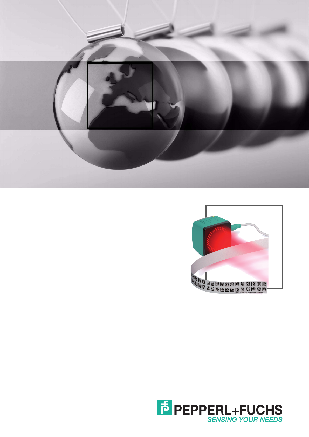
Data Matrix Positioning System

PCV...-F200-SSI-V19
With regard to the supply of products, the current issue of the following document is ap-
plicable: The General Terms of Delivery for Products and Services of the Electrical Indus-
try, published by the Central Association of the Electrical Industry (Zentralverband
Elektrotechnik und Elektroindustrie (ZVEI) e.V.) in its most recent version as well as the
supplementary clause: "Expanded reservation of proprietorship"

PCV...-F200-SSI-V19
1 Introduction................................................................................. 5
2 Declaration of conformity .......................................................... 6
2.1 CE conformity....................................................................................... 6
3 Safety........................................................................................... 7
3.1 Symbols relevant to safety.................................................................. 7
3.2 Intended use......................................................................................... 7
3.3 General safety instructions ................................................................. 7
4 Product Description ................................................................... 8
4.1 Use and Application............................................................................. 8
4.2 USB Interface........................................................................................ 8
4.3 SSI Interface ......................................................................................... 8
4.4 LED indicators and controls ............................................................... 9
4.5 Accessories ........................................................................................ 11
5 Installation................................................................................. 12
5.1 Installing the Code Reel .................................................................... 12
5.2 Mounting the Read Head................................................................... 15
5.3 Establishing the Electrical Connections ......................................... 17
6 Commissioning......................................................................... 20
6.1 Aligning the Read Head..................................................................... 20
6.2 Parameterizing ................................................................................... 20
6.2.1 Internal Parameterization Using Parameterization Software ............. 20
6.2.2 External parameterization using code cards .................................... 21
7 Operation and communication................................................ 23
7.1 Communication via the SSI Interface............................................... 23
7.2 Operating with event markers........................................................... 24
7.3 Operation with Repair Tape............................................................... 26
3

PCV...-F200-SSI-V19
8 Appendix ................................................................................... 27
8.1 Code Cards for External Parameterization ......................................27
8.1.1 Code Cards With Special Functions................................................. 27
8.1.2 Code cards for adjusting the output code......................................... 29
8.1.3 Code Cards for Adjusting the Resolution..........................................29
8.1.4 Code Cards for Setting the Orientation............................................. 30
8.1.5 Code cards for controlling image capture......................................... 31
8.1.6 Code cards for adjusting input / output 2 ..........................................32
8.1.7 Code cards for adjusting input / output 3 ..........................................34
4
PCV...-F200-SSI-V19
Introduction
1 Introduction
Congratulations
You have chosen a device manufactured by Pepperl+Fuchs. Pepperl+Fuchs develops,
produces and distributes electronic sensors and interface modules for the market of
automation technology on a worldwide scale.
Symbols used
The following sym bols are used in this manual:
Note!
This symbol draws your attention to important information.
Handling instructions
You will find handling instructions beside this symbol
Contact
If you have any questions about the device, its functions, or accessories, please contact us at:
Pepperl+Fuchs GmbH
Lilienthalstraße 200
68307 Mannheim
Telephone: +49 621 776-4411
Fax: +49 621 776-274411
E-Mail: fa-info@pepperl-fuchs.com
2015-09
5
PCV...-F200-SSI-V19
Declaration of conformity
2 Declaration of conformity
2.1 CE conformity
This product was developed and manufactured under observance of the applicable European
standards and guidelines.
Note!
A declaration of conformity can be requested from the manufacturer.
2015-09
6
PCV...-F200-SSI-V19
Safety
3 Safety
3.1 Symbols relevant to safety
Danger!
This symbol indicates an imminent danger.
Non-observance will result in personal injury or death.
Warning!
This symbol indicates a possible fault or danger.
Non-observance may cause personal injury or serious property damage.
Caution!
This symbol indicates a possible fault.
Non-observance could interrupt the device and any connected systems and plants, or result in
their complete failure.
3.2 Intended use
Combined with a code strip with printed Data Matrix codes, this device represents a highresolution positioning system that can be used in all applications where precision positioning is
required along extremely long travel paths, irrespective of whether the travel path is straight,
curved or with inclines or declines.
Read through these instructions thoroughly. Familiarize yourself with the device before
installing, mounting, or operating.
Always operate the device as described in these instructions to ensure that the device and
connected systems function correctly. The protection of operating personnel and plant is only
guaranteed if the device is operated in accordance with its intended use.
3.3 General safety instructions
Responsibility for planning, assembly, commissioning, operation, maintenance, and
dismounting lies with the plant operator.
Installation and commissioning of all devices must be performed by a trained professional only.
User modification and or repair are dangerous and will void the warranty and exclude the
manufacturer from any liability. If serious faults occur, stop using the device. Secure the device
against inadvertent operation. In the event of repairs, return the device to your local
Pepperl+Fuchs representative or sales office.
Note!
Disposal
Electronic waste is hazardous waste. When disposing of the equipment, observe the current
statutory requirements in the respective country of use, as well as local regulations.
2015-09
7
PCV...-F200-SSI-V19
Product Description
4 Product Description
4.1 Use and Application
The PCV read head is part of the positioning system in the Pepperl+Fuchs incident light
process. Its features include a cam era module and an integrated illum ination unit, enabling it to
detect position markers printed onto an adhesive code reel in the form of Data Matrix codes.
The code reel is usually mounted to a fixed part of the equipment in a stationary manner (e.g.,
elevator shaft, overhead conveyor mounting rails) and the read head is then mounted in parallel
to a moving "vehicle" (e.g., elevator car, overhead conveyor chassis).
Maximum Length of the Code Reel
Resolution of the Read Head [mm] Maximum Length of the Code Reel [km]
10 10
1 10
0.1 1.5
This positioning system can be used with an appropriate resolution in equipment with
extremely large layouts without restrictions.
The extensive yet user-friendly parameterization options as well as the freely configurable
inputs and outputs mean that the read head can easily be adapted to suit each application.
4.2 USB Interface
The user-friendly PCV Parameterization Tool can be used for extensive and optimum
configuration of the read head. This configuration software is available as a free download from
www.pepperl-fuchs.com. Follow the instructions that appear on your screen during the
installation.
You will need the parameterization cable (see Accessories) to establish a connection to the PC
(required for parameterization) and to set up an electrical power supply to the read head for
param eterization. The read head is connected to the "Service" connector.
Connecting the Service Interface
1. First connect the round plug connector to the read head.
2. Connect the plug-in power supply to the parameterization cable.
3. Plug the plug-in power supply into a socket.
The ring light of the read head and the "PWR/ADJ/ERR/NO CODE" LED2 lights up or
flashes.
4. You can now connect the USB plug-in connector to your PC.
4.3 SSI Interface
The controller and read head communicate via the SSI interface during operation. This is an
optically isolated RS422 interface. The controller sends a series of pulses via the clock+ and
clock- lines, and the read head responds synchronou sly with the 25-bit comprehensive
response telegram. You can define the structure and content of the response telegram using
the configuration software PCV Parameterization Tool.
This may include position data in an X- and Y-direction as well as speed and diagnostic data.
The read head is connected for communication via the SSI interface during live operation via
the "Main" connector.
2015-09
8
PCV...-F200-SSI-V19
COM
SSI DATA / CONFIG
OUT2 / ADJ Y
OUT3 / ADJ Z
PWR / ADJ
ERR / NO CODE
INTERNAL
DIAGNOSTIC
ADJUST
CONFIG
1
2
LED 1 2 3 4 5 6 7
Product Description
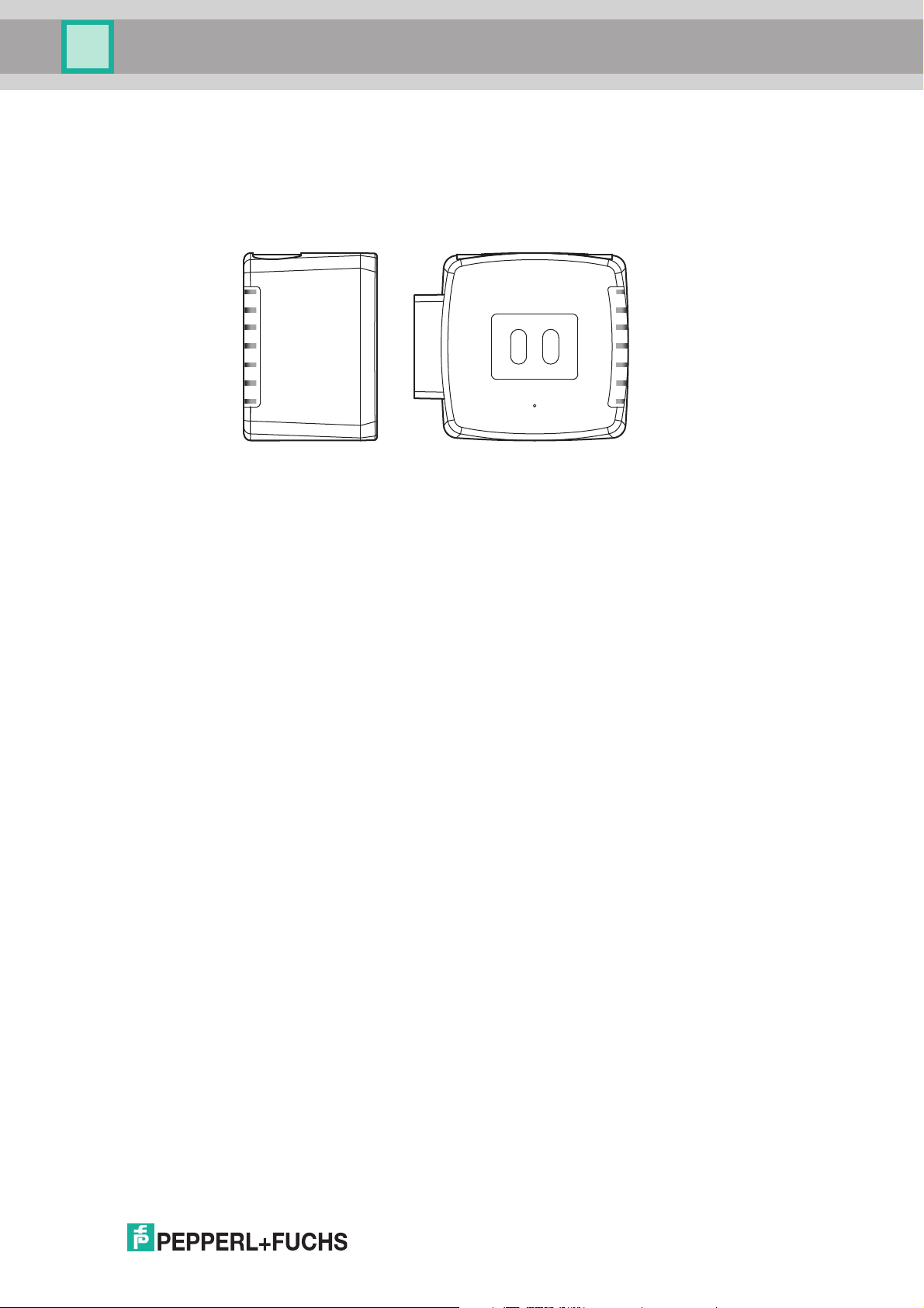
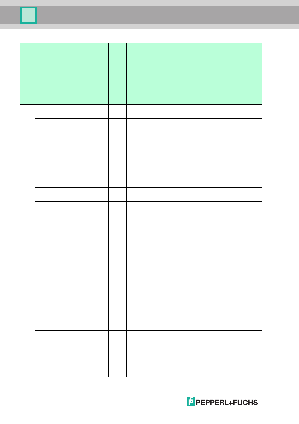
4.4 LED indicators and controls
The PCV... reading head is equipped with 7 indicator LEDs for performing visual function
checks and rapid diagnosis. For activating the alignment aid see chapter 6.1 and programming
mode, there are two buttons on the back of the reading head. ADJUST appears next to button
1 and CONFIG next to button 2.
2015-09
9
PCV...-F200-SSI-V19
Product Description
LED
[#1]
COM
[#2]
PWR / ADJ
ERR / NO CODE
[#3]
SSI DATA / CONFIG
[#4]
OUT 2 / ADJ Y
[#5]
OUT 3 / ADJ Z
green/re
d yellow yellow yellow yellow yellow
Flashes
Off
Off
Off
Off
Off
Off
Off
Off
green.
Flashes
green.
Flashes
green.
Flashes
green.
Flashes
green.
Flashes
green.
Flashes
red.
Lights
up red
Off Off Off Off Off
Off On Off Off Off
Off Flashes Off Off Off
Off Off Off Off Off
Off Off On Off Off
Off Off
Flashes
.
Off Off Off Off Off
Off Off Off Off Off
Lights
Off
up
Flashes x x Off Off
green.
State
Flashes
Off
Off
Flashes
red
Flashes
red
Flashes
red
Flashes x x Off Off
Off x x Off Off
Flashes FlashesFlashes Off Off
Off Off Flashes Off Off Off Off
Off Red, 3 sFlashes Off Off Off Off
Green,
Off
Flashes Off Off Off Off
1 s
x Off x x x Off Off Time lock for buttons disabled
Flashes Green Off Off Off Off Off
Flashes
Flashes
red
Off Off Off Off Off
x x x x x On On
[#6] +[#7]
Internal diagnostics
Off Off
DescriptionColor yellow
Alignment
Y > setpoint value; f
flash
= 2 Hz
Alignment
Y < setpoint value; f
flash
= 2 Hz
Alignment
Y = setpoint value; f
flash
= 2 Hz
Alignment
Z > setpoint value; f
flash
= 2 Hz
Alignment
Z < setpoint value; f
flash
= 2 Hz
Alignment
Z = setpoint value; f
flash
= 2 Hz
Alignment
Code strip outside read range; f
flash
= 2 Hz
System error
Normal mode, SSI communication active
f
= 2 Hz
flash
LEDs marked with x indicate the status of the
relevant output.
No code within read range, communication active
f
= 2 Hz
flash
LEDs marked with x indicate the status of the
relevant output.
No code within read range, no SSI
communication; f
flash
= 2 Hz
LEDs marked with x indicate the status of the
relevant output.
Normal operation. Displays for 2 s if a button
is pressed when the time lock is enabled.
Configuration mode active; f
Code card faulty; f
flash
= 2 Hz
flash
= 2 Hz
Code card detected
f
= 2 Hz
flash
Position detection via USB interface, code
within read range
Position detection via USB interface, no
code within read range
Internal error
Return to Pepperl+Fuchs
10
x = LED status has no meaning.
2015-09

PCV...-F200-SSI-V19
Product Description
4.5 Accessories
Compatible accessories offer enormous savings potential. Not only do you save a great deal of
time and work when commissioning, but also when replacing and servicing our products.
If harsh external environmental conditions prevail, appropriate Pepperl+Fuchs accessories can
extend the service life of the products used.
Model Number Description
V19-G-ABG-PG9-FE Grounding terminal and plug (set)
PCV-KBL-V19-STR-USB Cable unit for power supply
VAZ-V1S-B Cap for service connector
PCV-CM20-* Event marker
You can find the right connecting cable in the Accessories section of the read head data sheet
at http://www.pepperl-fuchs.com.
2015-09
11
PCV...-F200-SSI-V19
Installation
5 Installation
5.1 Installing the Code Reel
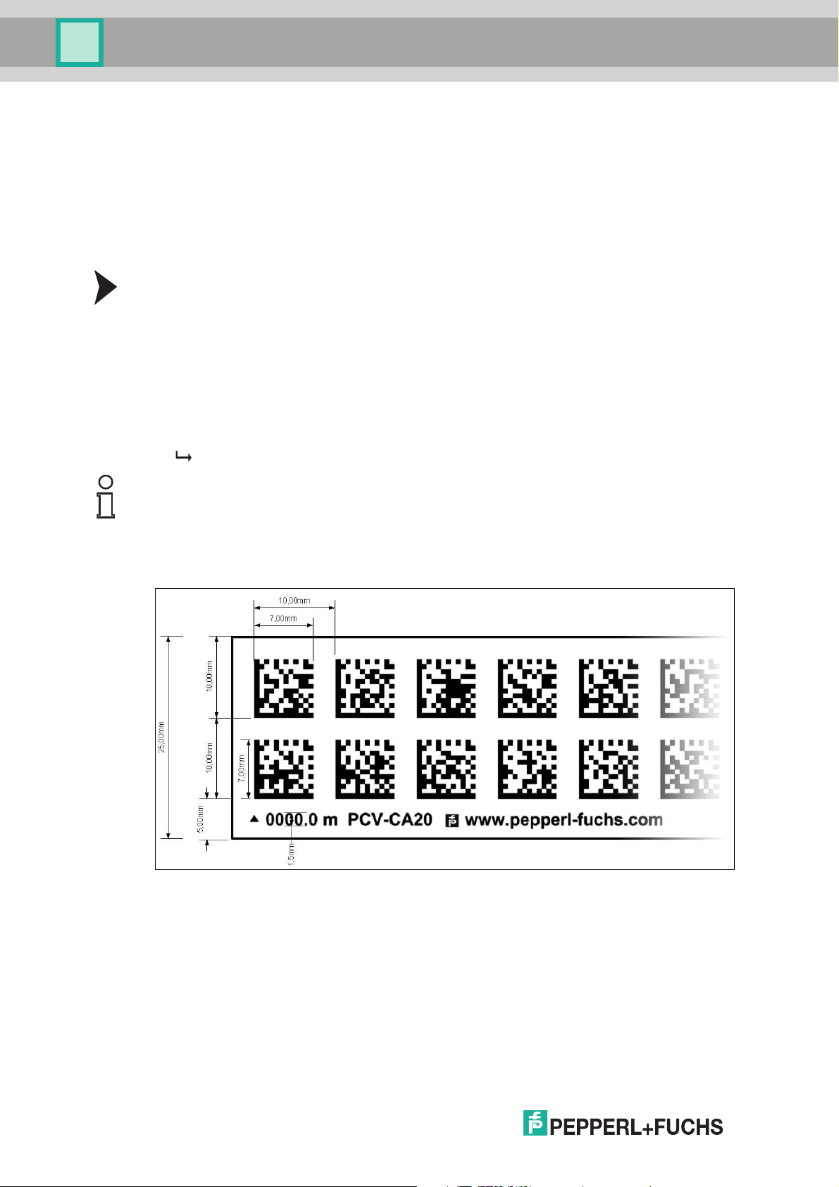
The code reel is made of silicone-free polyester film. A position marker appears every 100 mm
along the lower edge of the code reel (see "Dimensions, Code Reel"). This position marker is
used for various functions including precise positioning of the code reel during assembly.
The reverse side of the code reel carries a permanent modified acrylate-based adhesive. Affix
the self-adhesive code reel along the desired travel range. Proceed as follows:
Installing the Code Reel
1. Clean the surface of any greasy or oily deposits and dust.
2. Ensure that the surface is dry, clean, and stable.
3. Pull the protective foil at the beginning of the code reel a few centimeters forward. Place the
code reel at the precise point of the required starting position on the underside, and press to
attach.
4. Then affix the code reel along the desired travel range. Remove the protective film gradually
so that the code reel does not accidentally adhere to the surface in the incorrect position.
When affixing, ensure that the code reel does not crease or trap air bubbles.
The adhesive on the code reel hardens after 72 hours.
Note!
Thermal Expansion of the Code Reel
The heat expansion coefficient of the attached code reel corresponds to the heat expansion
coefficient of the underside.
Dimensions, Code Reel
12
Figure 5.1
2015-09
 Loading...