

Page 1
FACTORY AUTOMATION
MANUAL
PCV...-F200-B25-V1D
Data Matrix Positioning System
Page 2

PCV...-F200-B25-V1D
With regard to the supply of products, the current issue of the following document is ap-
plicable: The General Terms of Delivery for Products and Services of the Electrical Indus-
try, published by the Central Association of the Electrical Industry (Zentralverband
Elektrotechnik und Elektroindustrie (ZVEI) e.V.) in its most recent version as well as the
supplementary clause: "Expanded reservation of proprietorship"
Page 3

PCV...-F200-B25-V1D
1 Introduction................................................................................. 5
2 Declaration of conformity .......................................................... 6
2.1 CE conformity....................................................................................... 6
3 Safety........................................................................................... 7
3.1 Symbols relevant to safety.................................................................. 7
3.2 Intended use......................................................................................... 7
3.3 General safety instructions ................................................................. 7
4 Product Description ................................................................... 8
4.1 Use and Application............................................................................. 8
4.2 USB Interface........................................................................................ 8
4.3 EtherNet/IP Interface Pin Assignment .............................................. 8
4.4 LED Indicators and Controls............................................................... 8
4.5 Accessories ........................................................................................ 11
5 Installation................................................................................. 12
5.1 Installing the Code Reel .................................................................... 12
5.2 Mounting the Read Head................................................................... 15
5.3 Electrical Connection ........................................................................ 17
5.4 EtherNet/IP Connection..................................................................... 19
6 Commissioning......................................................................... 20
6.1 Aligning the Read Head..................................................................... 20
6.2 Parameterizing ................................................................................... 20
6.2.1 Internal Programming With Vision Configurator Software................. 20
6.2.2 External Parameterization Using Code Cards .................................. 21
3
Page 4

PCV...-F200-B25-V1D
7 Operation and communication................................................ 23
7.1 Communication via EtherNet/IP........................................................23
7.1.1 General Information on Communication via EtherNet/IP ................... 23
7.1.2 Setting the IP Address......................................................................23
7.1.3 EtherNet/IP objects .......................................................................... 26
7.1.4 Attributes of the Ethernet/Read Head IP Objects.............................. 27
7.2 Operation with Repair Tape ...............................................................33
7.3 Operating with event markers ...........................................................33
8 Appendix ................................................................................... 35
8.1 Code Cards for External Parameterization ......................................35
8.1.1 Code Cards With Special Functions................................................. 35
8.1.2 Code Cards for Adjusting the Resolution.......................................... 37
8.1.3 Code Cards for Setting the Orientation.............................................38
8.1.4 Code Cards for Adjusting Output 1................................................... 39
8.1.5 Code Cards for Adjusting Output 2................................................... 41
8.1.6 Code Cards for Adjusting Output 3................................................... 43
8.2 ASCII table...........................................................................................45
4
Page 5

PCV...-F200-B25-V1D
Introduction
1 Introduction
Congratulations
You have chosen a device manufactured by Pepperl+Fuchs. Pepperl+Fuchs develops,
produces and distributes electronic sensors and interface modules for the market of
automation technology on a worldwide scale.
Symbols used
The following sym bols are used in this manual:
Note!
This symbol draws your attention to important information.
Handling instructions
You will find handling instructions beside this symbol
Contact
If you have any questions about the device, its functions, or accessories, please contact us at:
Pepperl+Fuchs GmbH
Lilienthalstraße 200
68307 Mannheim
Telephone: +49 621 776-4411
Fax: +49 621 776-274411
E-Mail: fa-info@pepperl-fuchs.com
2015-09
5
Page 6

PCV...-F200-B25-V1D
Declaration of conformity
2 Declaration of conformity
2.1 CE conformity
This product was developed and manufactured under observance of the applicable European
standards and guidelines.
Note!
A declaration of conformity can be requested from the manufacturer.
2015-09
6
Page 7

PCV...-F200-B25-V1D
Safety
3 Safety
3.1 Symbols relevant to safety
Danger!
This symbol indicates an imminent danger.
Non-observance will result in personal injury or death.
Warning!
This symbol indicates a possible fault or danger.
Non-observance may cause personal injury or serious property damage.
Caution!
This symbol indicates a possible fault.
Non-observance could interrupt the device and any connected systems and plants, or result in
their complete failure.
3.2 Intended use
Combined with a code strip with printed Data Matrix codes, this device represents a highresolution positioning system that can be used in all applications where precision positioning is
required along extremely long travel paths, irrespective of whether the travel path is straight,
curved or with inclines or declines.
Read through these instructions thoroughly. Familiarize yourself with the device before
installing, mounting, or operating.
Always operate the device as described in these instructions to ensure that the device and
connected systems function correctly. The protection of operating personnel and plant is only
guaranteed if the device is operated in accordance with its intended use.
3.3 General safety instructions
Responsibility for planning, assembly, commissioning, operation, maintenance, and
dismounting lies with the plant operator.
Installation and commissioning of all devices must be performed by a trained professional only.
User modification and or repair are dangerous and will void the warranty and exclude the
manufacturer from any liability. If serious faults occur, stop using the device. Secure the device
against inadvertent operation. In the event of repairs, return the device to your local
Pepperl+Fuchs representative or sales office.
Note!
Disposal
Electronic waste is hazardous waste. When disposing of the equipment, observe the current
statutory requirements in the respective country of use, as well as local regulations.
2015-09
7
Page 8

PCV...-F200-B25-V1D
Product Description
4 Product Description
4.1 Use and Application
The PCV read head is part of the positioning system in the Pepperl+Fuchs incident light
process. Its features include a cam era module and an integrated illum ination unit, enabling it to
detect position markers printed onto an adhesive code reel in the form of Data Matrix codes.
The code reel is usually mounted to a fixed part of the equipment in a stationary manner (e.g.,
elevator shaft, overhead conveyor mounting rails) and the read head is then mounted in parallel
to a moving "vehicle" (e.g., elevator car, overhead conveyor chassis).
Maximum Length of the Code Tape
Resolution of the read head [mm] Maximum length of the code tape [km]
10 10
1 10
0.1 10
This positioning system can be used with an appropriate resolution in equipment with
extremely large layouts without restrictions.
The extensive yet user-friendly parameterization options as well as the freely configurable
inputs and outputs mean that the read head can easily be adapted to suit each application.
4.2 USB Interface
The Vision Configurator is a useful and easy-to-use piece of software for configuring the read
head. This configuration software is available as a free download from www.pepperlfuchs.com. Follow the instructions that appear on your screen during the installation.
The PC connection required for programming and the read head power supply can be made
using a special parameterization cable. This parameterization cable can be ordered as an
accessory under the name "Cable unit for service interface with the power supply". This also
provides the electrical supply to the read head. The parameterization cable is connected to the
read head using the "Main" connector.
Connection of the Parameterization Cable
1. First connect the round plug connector to the read head.
2. Connect the plug-in power supply to the parameterization cable.
3. Plug the plug-in power supply into a socket.
The ring light of the read head and the "PWR/ADJ/ERR/NO CODE" LED2 lights up or
flashes.
4. You can now connect the USB plug-in connector to your PC.
4.3 EtherNet/IP Interface Pin Assignment
The controller and read head communicate via the EtherNet/IP interface during operation. The
interface is based on Ethernet technology and works according to the CIP protocol (Common
Industrial Protocol).
The connection of the read head in ongoing operation is carried out via the "EtherNet/IP 1 & 2"
connectors.
4.4 LED Indicators and Controls
The PCV... read head is equipped with 6 indicator LEDs for performing visual function checks
and rapid diagnostics. The read head is equipped with 2 buttons on the back of the device for
activating the alignment aid (see chapter 6.1) and the parameterization mode. Button 1 is
labeled ADJUST. Button 2 is labeled CONFIG.
8
2015-09
Page 9

PCV...-F200-B25-V1D
ADJUST
CONFIG
1
2
LED 1 2 3 4 5 6
Product Description
Figure 4.1
2015-09
9
Page 10

PCV...-F200-B25-V1D
Product Description
LED
[#1]
BUS LINK
[#2]
BUS TX / RX
[#3]
PWR/ADJ
SYSERR/NO
CODE
[#4]
OUT 1/ADJ Y
[#5]
OUT 2/ADJ Z
[#6]
INTERNAL
DIAGNOSTIC
Red/green/
DescriptionColor Green Yellow Red/green Yellow Yellow
Alignment
Y > setpoint value
f
= 2 Hz
flash
Alignment
Y < setpoint value
f
= 2 Hz
flash
Alignment
Y = setpoint value
f
= 2 Hz
flash
Alignment
Z > setpoint value
f
= 2 Hz
flash
Alignment
Z < setpoint value
f
= 2 Hz
flash
Alignment
Z = setpoint value
f
= 2 Hz
flash
Status
Off Off
Off Off
Off Off
Off Off
Off Off
Off Off
Flashes
green
Flashes
green
Flashes
green
Flashes
green
Flashes
green
Flashes
green
yellow
Off Off Off
Lights
up
Off Off
Flashes Off Off
Off Off Off
Lights
Off
up
Off
Off Flashes Off
Alignment
Off Off Flashes red Off Off Off
x x
x x
Lights
up
Lights up
red
Lights up
green
x x x
x x x
x x x x x
Code tape outside read range
f
= 2 Hz
flash
System error
Normal operation, code tape detected
EtherNet/IP-connection active
x Flashes x x x x EtherNet/IP TX/RX data transfer
x x Flashes red x x x
x x x x On On
Code not recognized
f
= 2 Hz
flash
Internal error
Return to Pepperl+Fuchs
10
x = LED status has no meaning
2015-09
Page 11

PCV...-F200-B25-V1D
Product Description
4.5 Accessories
Compatible accessories offer enormous potential for cost savings. Such accessories not only
save you a great deal of time and effort when commissioning for the first time, but also when
replacing and servicing our products.
If products are used in harsh ambient conditions, appropriate Pepperl+Fuchs accessories can
be used to extend the service life of these products.
Model number Description
V19-G-ABG-PG9-FE Grounding terminal and plug (set)
PCV-SC12
PCV-SC12A
V1SD-G-*M-PUR-ABG-V1SD-G Ethernet bus cable, M12 to M12, available in
VAZ-V1S-B Stopping plug for M12 connector
V19-G-*M-*
PCV-CM20-0* Event marker
PCV-CR20 Repair tape
PCV-KBL-V19-STR-USB Cable unit for power supply
Vision Configurator Software Software for camera-based sensors for
Grounding clip
several different lengths
Configurable connection cable
convenient programming
1)
1)
: Ask your contact person at Pepperl+Fuchs
2015-09
11
Page 12

PCV...-F200-B25-V1D
Installation
5 Installation
5.1 Installing the Code Reel
The code reel is made of silicone-free polyester film. A position marker appears every 100 mm
along the lower edge of the code reel (see "Dimensions, Code Reel"). This position marker is
used for various functions including precise positioning of the code reel during assembly.
The reverse side of the code reel carries a permanent modified acrylate-based adhesive. Affix
the self-adhesive code reel along the desired travel range. Proceed as follows:
Installing the Code Reel
1. Clean the surface of any greasy or oily deposits and dust.
2. Ensure that the surface is dry, clean, and stable.
3. Pull the protective foil at the beginning of the code reel a few centimeters forward. Place the
code reel at the precise point of the required starting position on the underside, and press to
attach.
4. Then affix the code reel along the desired travel range. Remove the protective film gradually
so that the code reel does not accidentally adhere to the surface in the incorrect position.
When affixing, ensure that the code reel does not crease or trap air bubbles.
The adhesive on the code reel hardens after 72 hours.
Note!
Thermal Expansion of the Code Reel
The heat expansion coefficient of the attached code reel corresponds to the heat expansion
coefficient of the underside.
Dimensions, Code Reel
12
Figure 5.1
2015-09
Page 13
PCV...-F200-B25-V1D
Y
Z
X
Installation
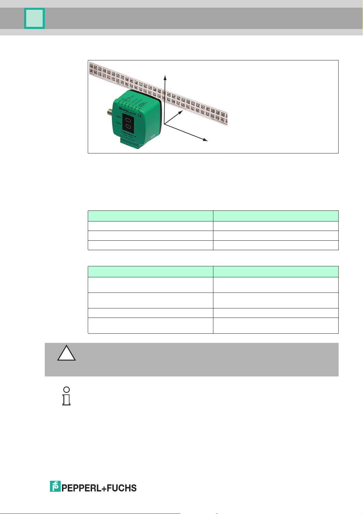
Orientation of the Code Reel and Read Head
Figure 5.2
Position the code reel so that the ww w.pepperl-fuchs.com label and the position markings
are below the data matrix code. The position values then increase along the X-direction. The
diagram shows the orientation of a read head in the default position of 0°. The read head can
be configured in the interface for other installation situations.
Code Reels with a Starting Position of 0 m
Model Number Description
PCV6M-CA20-0 Code reel, 2-track, length: 6 m
... ...
PCV100M-CA20-0 Code reel, 2-track, length: 100 m
Code Reels with Different Starting Positions
Model Number Description
PCV100M-CA20-0 Code reel, 2-track, length: 100 m, starting
position: 0 m
PCV100M-CA20-10000 Code reel, 2-track, length: 100 m, starting
position: 100 m
... ...
PCV100M-CA20-990000 Code reel, 2-track, length: 100 m, starting
position: 9,900 m
Caution!
Stop Edges
If you attach another code reel at the end of a previous code reel, the code pattern of 10 mm
must be retained.
Note!
Expansion Joints
If the system covers longer distances, expansion joints are integrated in the system structure.
We recommend creating breaks along the code reel. The resulting gaps should be 20 mm (2
code grids).
2015-09
13
Page 14
PCV...-F200-B25-V1D
Installation
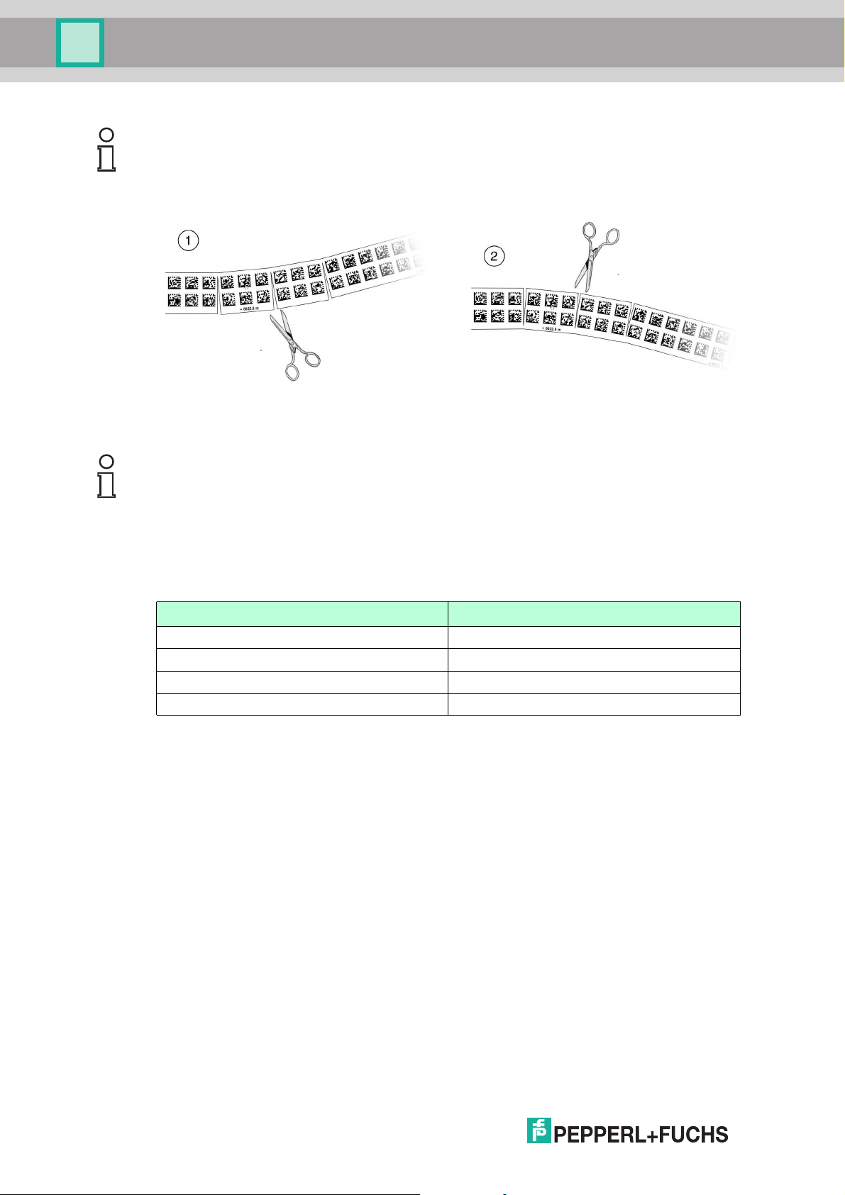
Note!
Inclines and Declines
If you mount the code reel on inclines or declines, cut the code reel several times at the
transition point to the horizontal as shown.
1. Incline
2. Decline
Note!
Code Reels with Different Row Numbers
The PCV-CA20 code reel has two rows of code to compensate for slight deviations in the travel
range in the Y-direction. The code reel is also available with other row numbers. The order code
for the code reel is PCV-CAx0, whereby x represents the number of rows of code, which can be
either 1 or 2. More rows are available on request–contact us for more information.
Code Reels with Different Numbers of Tracks
Model Number Description
PCV*M-CA10-* Code reel, 1-track
PCV*M-CA20-* Code reel, 2-track
PCV*M-CA40-* Code reel, 4-track
... ...
14
2015-09
Page 15

PCV...-F200-B25-V1D
Y
0
X
Y
0
X
Installation
Hysteresis Y-Axis
Figure 5.3 Zero line for code reels
If the read head leaves the zero line when traveling the X-axis, different threshold values will
result depending on the number of tracks. If the deviation exceeds this threshold, a warning
code is issued.
Y-Axis Deviation Thresholds
Code reel Threshold
Number of tracks Width Exit Entry
1 15 mm ± 10 mm ± 6 mm
2 25 mm ± 15 mm ± 11 mm
4 45 mm ± 25 mm ± 21 mm
6 65 mm ± 35 mm ± 31 mm
8 85 mm ± 45 mm ± 41 mm
5.2 Mounting the Read Head
Mount the PCV... read head on the moving part of your equipment using the four screws on the
mounting adapter of the read head. Mount the read head in such a way that the lens with ring
2015-09
light and camera module are aligned toward the code tape.
The stability of the mounting and the guidance of the moving system component must be such
that the field of the depth of focus of the read head is not exited during operation.
The distance between the read head and the code tape should be the same as the read
distance of the read head.
15
Page 16

PCV...-F200-B25-V1D
Read distance
Code reel
10°
10°
Read distance
10°
10°
Installation
Figure 5.4 Vertical alignment tolerance
16
Figure 5.5 Horizontal alignment tolerance
Optimum Read Distance (Z-Axis)
Model Number Read Distance [mm] Depth of Focus [mm]
PCV50* 50 ± 25
PCV80* 80 ± 15
PCV100* 100 ± 20
PCV100*-...-6011 100 ± 40
2015-09
Page 17

PCV...-F200-B25-V1D
70
80
38.5
70 14.5
1
2
22
51
ø 25
12
M12 x 1
9
4 x M6
20 20
1
2
3
4
5
6
7
8
OUT 2 / IN 2
+ UB
USB_DM
USB_DP
OUT 1
IN 1
GND
OUT 3 / IN 3
Main
Installation
Read Head Dimensions
Figure 5.6
Caution!
When selecting mounting screws, ensure that the maximum insertion depth of the screws in
the threaded inserts on the read head is 8 m m.
Using longer screws can damage the read head.
Caution!
The maximum torque of the mounting screws must not exceed 9 Nm.
Tightening the screws to a higher torque can damage the read head.
5.3 Electrical Connection
The PCV... read head is connected electrically via an 8-pin M12 x 1 connector on the side of
the housing. The power supply and communication with peripheral devices are established via
this connection. The configurable inputs and outputs on the read head are also located at this
connection.
The port also serves as a service interface for programming the read head (see "USB
interface" in this manual).
2015-09
Figure 5.7
17
Page 18

PCV...-F200-B25-V1D
1
4
6
7
8
53
2
Main
Installation
Connector Occupancy
Figure 5.8
Color Assignment
Pepperl+Fuchs cordsets (female) are manufactured in accordance with EN60947-5-2. When
using a type V19-... () female cordset with an open cable end on the Main connection, the
colors are assigned as follows:
Connection pin Strand color Color abbreviation
1 White WH
2 Brown BN
3 Green GN
4 Yellow YE
5 Gray GY
6 Pink PK
7 Blue BU
8 Red RD
Shielding Cables
The shielding of connection lines is required to suppress electromagnetic interference.
Establishing a low resistance or low impedance connection with the conductor or equipotential
bonding circuit is a particularly important factor in ensuring that these interference currents do
not become a source of interference themselves. Always use connection lines with braided
shield; never use connection lines with a film shield. The shield is integrated at both ends, i.e.,
in the switch cabinet or on the controller and on the read head. The grounding terminal
available as an accessory allows easy integration in the equipotential bonding circuit.
In exceptional cases, the shielding of a connection at one end may be more favorable if
■
An equipotential bonding cable is not laid or cannot be laid.
■
A film shield is used.
The following points relating to shielding m ust also be noted:
■
Use metal cable clips that cover large areas of the shield.
■
After installing the cable shield in the control cabinet, place it directly on the equipotential
bonding rail.
■
Direct the protective grounding connections to a common point in a star configuration.
■
The cross-section of the cables used for grounding should be as large as possible.
Additional Ground Connection
Model number Description
PCV-SC12 Clip for mounting an additional ground
PCV-SC12A
connection.
2015-09
18
Page 19

PCV...-F200-B25-V1D
1
2
3
4
TX +
RX +
TX -
RX -
Bus
EtherNet/IP 1 & 2
1
3
4
2
Installation
Caution!
Damage to the device
Connecting an alternating current or excessive supply voltage can damage the device or cause
the device to malfunction.
Electrical connections with reversed polarity can damage the device or cause the device to
malfunction.
Connect the device to direct current (DC). Ensure that the supply voltage rating is within the
specified device range. Ensure that the connecting wires on the female cordset are connected
correctly.
5.4 EtherNet/IP Connection
The PCV... read head is connected to EtherNet/IP via two 4-pin, D-coded device sockets, M12
x 1, EtherNet/IP 1 and EtherNet/IP 2, on the side of the housing.
Figure 5.9
Connector Occupancy
Figure 5.10
For suitable Ethernet cables, see see chapter 4.5.
2015-09
19
Page 20

PCV...-F200-B25-V1D
Y
Z
X
Commissioning
6 Commissioning
6.1 Aligning the Read Head
An integrated alignment aid is available to help you align the Y and Z coordinates of the read
head easily and precisely with respect to the code reel.
Note!
The activation of the alignment aid is possible only within 10 minutes of switching on the read
head.
The switchover from normal operation to param eterization mode is via button 1 on the back of
the read head.
Activating the Alignment Aid
1. Press button 1 for longer than 2 seconds.
LED2 flashes green for a recognized code reel. LED2 flashes red for an unrecognized
code reel. .
2. Align the Z and Y coordinates of the read head. The integral LED indicators provide
assistance here.
Z coordinate: If the distance of the camera to the code reel is too small, the yellow LED5 lights
up. If the distance is too great, the yellow LED5 goes out. The yellow LED5 flashes at the same
time as the green LED2 when within the target range. .
Set the distance between the read head and the code reel so that the yellow LED5 and the
green LED2 flash synchronously.
Y coordinate: If the optical axis of the read head is too low relative to the middle of the code
reel, the yellow LED4 lights up, . If the optical axis is too high, the yellow LED4 goes out. Within
the target range, the yellow LED4 flashes at the same time as the green LED2.
Set the optimal height of the read head relative to the code reel so that the yellow LED4 flashes
in rhythm with the green LED2.
Briefly pressing button 1 ends the alignment aid, and the read head returns to normal
operation.
6.2 Parameterizing
The PCV... reading head can be adapted to specific requirements through parameterization.
The reading head can be parameterized via the service interface (internal parameterization) or
via optical parameterization codes (external parameterization).
6.2.1 Internal Programming With Vision Configurator Software
Internal parameterization of the read head via the USB interface must be started within 10
minutes of the read head being switched on. A time lock disables the read head once this time
has elapsed. The time lock remains inactive during the parameterization process. The time
lock disables the read head only if no parameterization activities take place for more than 10
minutes.
2015-09
20
Page 21

PCV...-F200-B25-V1D
Commissioning
The Vision Configurator is a useful and easy-to-use piece of software for configuring the read
head. This configuration software is available as a free download from ww w.pepperlfuchs.com. Follow the instructions that appear on your screen during the installation.
The PC connection required for programming and the read head power supply can be m ade
using a special parameterization cable. This parameterization cable can be ordered as an
accessory under the name "Cable unit for service interface with the power supply". This also
provides the electrical supply to the read head. The parameterization cable is connected to the
read head using the "Main" connector.
Connection of the Parameterization Cable
1. First connect the round plug connector to the read head.
2. Connect the plug-in power supply to the parameterization cable.
3. Plug the plug-in power supply into a socket.
The ring light of the read head and the "PWR/ADJ/ERR/NO CODE" LED2 lights up or
flashes.
4. You can now connect the USB plug-in connector to your PC.
Parameterizing the read head
1. Start the Vision Configurator software on the PC.
2. Program the read head with the help of the "Vision Configurator" m anual.
3. Transfer the parameter list to the read head.
4. Save the parameterization.
5. Unplug the plug-in power supply from the wall outlet to turn off the power supply at the head.
6. Remove the parameterization cable's USB plug-in connector from your PC
7. Remove the configuration cable from the read head.
The read head is now parameterized according to your specifications and can be used in
your application.
6.2.2 External Parameterization Using Code Cards
During external parameterization, the read head scans special code cards optically and
configures the relevant parameters. Simply hold the corresponding code cards at the correct
distance in front of the lens on the PCV...-F200- read head. The standard code cards are
contained in the appendix.
The following param eters can be configured using code cards:
■
Read head resolution [0.1 mm, 1 mm, 10 mm]
■
Read head orientation [0° ; 180°; 0° or 180°, 0°, 90°, 180° or 270°]
■
Function of output 1 [none, speed exceeded, warning, fault, contamination, event, no
position]
■
Function of output 2 [none, speed exceeded, warning, fault, contamination, event, no
position]
■
Function of output 3 [none, speed exceeded, warning, fault, contamination, event, no
position]
2015-09
21
Page 22

PCV...-F200-B25-V1D
Commissioning
Programming mode activation
Note!
External parameterization of the read head using code cards must be started within 10 minutes
of the read head switching on. A time lock disables the read head once this time has elapsed.
The time lock remains inactive during the parameterization process. The time lock disables the
read head only if no parameterization activities take place for m ore than 10 minutes.
If a button is pressed when the time lock is enabled, all LEDs flash and remain lit for 2 seconds
during each flashing cycle.
The switchover from normal mode to parameterization mode is made by pressing button 2 on
the back of the read head.
Parameterization Mode Activation
1. Press button 2 for longer than 2 s.
Yellow LED3 now flashes.
2. Hold the "ENABLE" code in front of the camera system on the read head to trigger final
activation
If the "EN ABLE" activation code is detected, the green LED2 lights up for 1 sec. If the
activation code is not detected, LED2 lights up red for 2 seconds.
Parameterization
Place the parameterization code in the field of vision of the camera module.
After the parameterization code is detected, the green LED2 lights up for 1 sec. In the event
of an invalid parameterization code, LED2 lights up red for 2 seconds.
Exiting Parameterization Mode
Hold the "STORE" code in front of the cam era system on the read head to save the
configuration
When the "STORE" memory code is detected, the green LED2 lights up for 1 sec. The
param eterization is stored in the nonvolatile memory of the read head and param eterization
mode is terminated. Parameterization of the read head is now complete. If the memory code is
not detected, LED2 lights up red for 2 seconds.
Note!
Press button 2 briefly to exit parameterization mode. Any parameter changes that are made but
have not yet been saved are discarded. The read head operates with the last valid parameters
that were saved.
The code cards "CANCEL", "USE", and "DEFAULT"
Holding one of these cards in front of the reading head exits parameterization mode with the
following consequences:
■
CANCEL:
All parameter changes that are made but have not yet been saved are discarded. The
reading head operates with the last valid parameters that were saved.
■
USE:
22
For test purposes, the reading head operates with the parameters that have just been
modified. The parameterization is not saved, however. After being switched off and on
again, the reading head operates with the last valid parameters that were saved.
■
DEFAULT:
All parameters in the reading head are overwritten with the original default settings. Reenter the configuration mode and save the default settings nonvolatile with the code card
STORE.
2015-09
Page 23

PCV...-F200-B25-V1D
Operation and communication
7 Operation and communication
7.1 Communication via EtherNet/IP
7.1.1 General Information on Communication via EtherNet/IP
The read head communicates with the controller (e.g., PLC) via EtherNet/IP. An object-oriented
fieldbus system for exchanging data between nodes based on Ethernet technology.
The management and development of the EtherNet/IP standards are subject to the Open
DeviceNet Vendor Association (ODVA). More information on EtherNet/IP will be supplied on
request by the Open DeviceNet Vendor Association (ODVA) at the following Internet address:
ODVA, Inc
4220 Varsity Drive, Suite A
Ann Arbor, MI 48108-5006 USA
http://www.odva.org e-mail: mailto:odva@odva.org
The basic properties of the interface are:
■
Transfer rate 10 Mbit/s or 100 Mbit/s, half or full duplex operation
■
Automatic negotiation of the transfer rate and the duplex method (auto-negotiation)
■
Automatic setting for crossed lines (auto-crossover)
EtherNet/IP protocol works according to the CIP protocol (Common Industrial Protocol) and is
used to control, configure, monitor, and collect data. Time-sensitive data exchange (implicit
messaging) takes place using the UDP/IP protocol and non-time-sensitive data exchange
(explicit messaging) using the TCP/IP protocol.
The read head supports the following features:
■
"Listen only", "Input only", and "Exclusive Owner" connection types
■
Message transmission as "Multipoint data transfer" (Multicast) and "Point-to-point data
transfer" (Unicast)
■
Cycle time (request packet interval) ≥ 2 ms
■
Dynamic Host Configuration Protocol (DHCP)
■
Device Level Ring (DLR)
■
Address Conflict Detection (ACD)
The read head is integrated in the network via a EDS file (electronic data sheet) with a
configuration tool such as RSLOGIX5000. The EDS file contains all of the information about
device-specific parameters and operating modes.
Downloading the EDS file
You can find the relevant EDS file in the Software section of the product detail page for the
device.
To access the product detail page for the device, go to http://www.pepperl-fuchs.com and type
information about the device (e.g., the product description or the item number) into the search
function.
7.1.2 Setting the IP Address
The read head is delivered in DHCP mode and waits for an address assignment from the
control system.
The following section describes the address assignment via the software BOOT/DHCP server
from Rockwell Automation as an example.
2015-09
23
Page 24

PCV...-F200-B25-V1D
Operation and communication
1. Connect the read head with the DHCP server.
2. Start the BOOT/DHCP server software.
3. Enter the following data in the Network Settings menu:
- Subnet Mask "255.255.255.0 "
- Gateway "192.168.1.1"
- the remaining fields are not filled in.
4. Switch on the supply voltage to the read head.
24
The read head cyclically carries out DH CP requests. This enters the MAC address of the
read head in the Request History field to the list.
5. Enter the desired IP address in the New Entry menu.
- The software automatically adopts the MAC address of the read head.
- The "hostname" function is not supported.
- You may enter text under "Description".
2015-09
Page 25

PCV...-F200-B25-V1D
Operation and communication
6. Confirm the entries of the address data using OK.
The IP address is assigned to the read head on the next DHCP request. The new
address data will be displayed in the Relation List field.
7. Press the Disable BOOTP/DHCP key in the Relation List field.
In this way, the assigned IP address is saved permanently in the read head.
2015-09
25
Page 26

PCV...-F200-B25-V1D
Operation and communication
7.1.3 EtherNet/IP objects
All the data and functions of the read head are defined via objects in accordance with the
EtherNet/IP standards. The read head corresponds to the "Encoder Device Type 0x22" device
profile.
The read head supports the following listed standard and product-specific classes.
Standard classes
Class ID Class description
0x01 Identity Object
0x02 Message Router Object
0x04 Assembly Object
0x06 Connection Manager Object
0xF5 TCP/IP Interface Object
0xF6 Ethernet Link Object
0X47 DLR Object
0X48 Quality of Ser vice
Product-specific class
Class ID Class description
0x23 Position Sensor Object
26
The parameters are not directly addressable from the network with the "Set" or "Get" attribute
services. Access is via Assembly Objects (Class Code 0x04)
2015-09
Page 27

PCV...-F200-B25-V1D
Operation and communication
Cyclic data communication with assembly objects (Class Code 0x04)
Assemblies are special CIP objects used for cyclic data communication (implicit messaging).
These are composed of one or more attributes of various objects. These objects allow you to
send or receive data from multiple objects by means of a connection. The composition of the
assemblies in the read head is fixed and cannot be modified by the user.
Input assemblies
Instance
no. Description Size [byte] Attribute
1 Position 4 Position Value Signed
100 Position + speed 8 Position Value Signed
101 Status, X-position, Y-
position, Speed,
Warning, Event
Attribute
ID Data type
10 DINT
(X-Position)
10 DINT
(X-Position)
Velocity Value 24 DINT
18 Status Word 100 UINT
Position Value Signed
(X-Position)
Y-position 101 DINT
Velocity Value 24 DINT
Warning flags 102 UINT
Event number 103 UINT
10 DINT
Addresses required for the various connection types
The connection type defines the connection between the control system (originator), in this
case the controls, and the target device (target), in this case the read head. The following
options are available for data traffic.
Data from the control system to the destination device
Instance no. (dec.) Size [byte] Connection type
192 0 Listen only
193 0 Input only
Data from the target device to the control system
Instance no. (dec.) Size [byte] Assemblies
1 4 Position
100 8 Position + speed
101 18 Status, X-position, Y-position,
7.1.4 Attributes of the Ethernet/Read Head IP Objects
Position Sensor Object attributes (Class ID 0x23)
Speed, Warning, Event (lists
only)
Class attributes
ID Name Access Data type Size [byte] Description
1 Revision - UINT 2 Object
inspection
2015-09
27
Page 28

PCV...-F200-B25-V1D
Operation and communication
Standard instance attributes for object 0x23
ID Attribute Access Data type Size [byte] Description
10 Position Value
Signed (XPosition)
24 Velocity Value - DINT 4 Speed
Specific read head attributes
ID Attribute Access Data type Size [byte] Description
100 Status Word - UINT 2 Status Information
101 Y-position - UINT 4 Y-position in two's
102 Warning flags - UINT 2 Warnings
103 Event number - UINT 2 Event marker number
Basic data structure
- DINT 4 X-Position in two's
complement
complement
1 byte = 8-bit value
Byte 4 Byte 3 Byte 2 Byte 1
Example: XP31 ... XP24
MSB (Most Significant
Byte)
Example: XP23
... XP16
Example: XP15
... XP08
Exam ple: XP07 ... XP00
LSB (least significant byte)
Position data X: Position Value Signed (ID 10)
Size Type Content
4 byte consistent Input data 32-bit X data
LSB first
LSB = least significant byte
Resolution: 0.1 mm, 1 mm, 10 mm, binar y coded
At a resolution of 1 mm and 10 mm: L
10,000,000 mm
The following default settings apply:
■
The X position is output in the two's complement.
■
The value is output in the set resolution of the device.
■
The default is mm.
■
If the ERR bit is set in the "status word (ID 100)" attribute, the error number is transferred
to this attribute.
10.00 km =
max =
28
Data of the attribute 10
Bit 7 Bit 6 Bit 5 Bit 4 Bit 3 Bit 2 Bit 2 Bit 0
Byte 1 XP07 XP06 XP05 XP04 XP03 XP02 XP01 XP00
Byte 2 XP15 XP14 XP13 XP12 XP11 XP10 XP09 XP08
Byte 3 XP23 XP22 XP21 XP20 XP19 XP18 XP17 XP16
Byte 4 XP31 XP30 XP29 XP28 XP27 XP26 XP25 XP24
2015-09
Page 29

PCV...-F200-B25-V1D
Operation and communication
Position data Y: Y position (ID 101)
Size Type Content
4 byte consistent Input data 32-bit Y data
The following default settings apply:
■
The Y position is output in the two's complement.
■
The value is output in the set resolution of the device.
■
The default is mm.
Data of the attribute 101
Bit 7 Bit 6 Bit 5 Bit 4 Bit 3 Bit 2 Bit 2 Bit 0
Byte 1 YP07 YP06 YP05 YP04 YP03 YP02 YP01 YP00
Byte 2 YP15 YP14 YP13 YP12 Y P11 YP10 YP09 YP08
Byte 3 YP23 YP22 YP21 YP20 Y P19 YP18 YP17 YP16
Byte 4 YP31 YP30 YP29 YP28 Y P27 YP26 YP25 YP24
LSB first
Resolution: 0.1 mm, 1 mm, 10 mm, binar y coded in
two's com plem ent
Speed Data: Velocity Value (ID 24)
Size Type Content
4 byte consistent Input data 32-bit speed data
Resolution: 0.1 m/s, 0.01 m/s, 0.001 m/s, binary coded
Speed from 0 ... 12.5 m/s
Example: Speed = 4.7 m/s --> speed output = 47 at a
resolution of 0.1 m/s
65535 for unknown speed
The following default settings apply:
■
The value is output in the set resolution of the device.
■
The default is dm/s.
Data of attribute 24
Bit 7 Bit 6 Bit 5 Bit 4 Bit 3 Bit 2 Bit 2 Bit 0
Byte 1 SP07 SP06 SP05 SP04 SP03 SP02 SP01 SP00
Byte 2 SP15 SP14 SP13 SP12 SP11 SP10 SP09 SP08
Byte 3 SP23 SP22 SP21 SP20 SP19 SP18 SP17 SP16
Byte 4 SP31 SP30 SP29 SP28 SP27 SP26 SP25 SP24
2015-09
29
Page 30

PCV...-F200-B25-V1D
Operation and communication
Status: Status word (ID 100)
Size Type Content
2 bytes Input data 16-bit status
If the ERR bit is set, there is an error. The error num ber is transmitted to the "Value signed (ID
10)" attribute.
Data of attribute 100
Bit no.
1 ERR Error message (error code in
2 NP N o position information/OUT
3 WRN Warnings present; see
4 EV Event present see Event
5 0 -
... ... -
16 0 -
Content
Byte 1, 2
Status
Function
XP00–XP15); remaining bits =
0, see Error Codes
(XP = 0, YP = 0, SP = 0)
Warning Attribute
Attribute
Error codes
Error code Description Priority
1 Read head tipped 180° 2
2 No clear position can be determined (difference between codes
is too great, code distance incorrect, etc.)
> 1000 Internal error 1
3
30
2015-09
Page 31

PCV...-F200-B25-V1D
Operation and communication
Event: Event marker no. (ID 103)
Size Type Content
2 byte consistent Input data Last event marker
The event marker no. is binary coded and unsigned.
Data of attribute 103
Bit no.
1 EV00
2 EV01
3 EV02
4 EV03
5 EV04
6 EV05
7 EV06
8 EV07
9 EV08
10 EV09
11 0
... ...
16 0
Last event no.
Content
Byte 1, 2
Last event marker data
2015-09
31
Page 32

PCV...-F200-B25-V1D
Operation and communication
Warning: warning flags (ID 102)
Size Type Content
2 byte consistent Input data Last warnings
A set bit indicates that the corresponding warning is active.
Data of attribute 102
Bit no.
1 WRN00
2 WRN01
3 WRN02
4 WRN03
5 WRN04
6 WRN05
7 WRN06
8 WRN07
9 WRN08
10 WRN09
11 WRN10
12 WRN11
13 WRN12
14 WRN13
15 WRN14
16 WRN15
Last warning no.
Content
Byte 1, 2
Last warning data
32
Warning data set
Content
Bit no.
1 WRN01 A code with non-read head (PCV) content was found.
2 WRN02 Read head too close to code tape
3 WRN03 Read head too far from code tape
4 WRN04 Y position too large. The sensor is just before OUT
5 WRN05 Y position too small. The sensor is just before OUT
6 WRN06 The read head is rotated or tipped in relation to the code tape
7 WRN07 Low level of code contrast
8 WRN08 Repair tape detected
9 WRN09 Temperature too high
10 WRN10 Reser ved
11 WRN11 Reser ved
12 WRN12 Reser ved
13 WRN13 Reser ved
14 WRN14 Reser ved
15 WRN15 Reser ved
DescriptionByte 1, 2
2015-09
Page 33

PCV...-F200-B25-V1D
Operation and communication
Note!
If no warnings are present, all bits in the warning data set are set to 0.
7.2 Operation with Repair Tape
The repair tape is a short code reel with a length of one meter. The repair tape is used to bridge
defective or damaged areas of an existing code reel.
1. Cut the repair tape to the required length
2. Cover the defective area of the code reel with the repair tape
Note!
When placing a repair tape on the code reel, make sure that the repair tape represents as
accurate a continuation of the grid on the code reel as possible.
When the read head enters the range of a repair tape, it sets an event flag in the output data.
You also have the option of triggering a defined action when an event occurs by parameterizing
one of the outputs accordingly (). Actions of this type can be initiated when a certain event, all
events, or events from an event list occur.
Note!
The repair tape works incrementally. In so doing, it adds one value to the previous read position
on the code reel. If the read head starts on a repair tape, the read head reports an error. Move
the read head to a position on the code reel away from the repair tape to read the absolute
value.
Tip
If repairs are required, the Code Reel Generator at www.pepperl-fuchs.com can be used as a
short-term workaround. This allows code reel segments to be generated and printed out online.
Enter the start value in meters and the code reel length of the section to be replaced in meters.
This produces a printable PDF file with the required segment of the code reel.
Only use the printout as an emergency solution. The durability of the paper strip varies greatly
depending on the application!
Refer to the Accessories chapter for order information relating to repair tape.
7.3 Operating with event markers
In numerous position coding system applications, defined processes must be started at
specific positions so that the controller can evaluate the position data measured by the reading
head. However, this means that the exact positions for triggering events of this kind must be
defined as early as the system planning stage and can no longer be modified during the
construction phase or commissioning. If modifications are made, the position data stored in the
control software must be adapted accordingly, which involves a great deal of time and effort.
Activating a process through the detection of so-called event markers is a much more flexible
method. Only a specific event and the process linked with the event have to be programm ed
into the system controller. The position in which the corresponding event marker is placed
along the code strip can be decided immediately before final commissioning of the system.
Even if subsequent changes are made to the layout of a system, the relevant event marker is
simply moved to the new position without requiring program modifications.
Event markers are short code strips one meter in length. The event marker bears the encoded
event number and position information in incremental form. Event markers are available with
event numbers from 001 to 999. To transfer the exact position data, the reading head calculates
the last absolute position of the code strip before it entered the event range and adds the
2015-09
incremental offset from the codes of the event markers.
33
Page 34

PCV...-F200-B25-V1D
Operation and communication
When the reading head enters the range of an event m arker, it sets an event flag in the output
data. You also have the option of triggering a defined action when an event occurs by
param eterizing one of the outputs accordingly (). Actions of this type can be initiated when a
certain event, all events or events from an event list occur.
The 1 meter long event marker can be shortened. However, the minimum length should be 30
mm (3 codes). If the travel speed of the reading head increases, a longer event marker is
required. If the reading head travels at maximum speed, a full length event m arker of 1 meter
must be positioned over the code strip.
The minimum length of an event marker can be calculated according to the following formula
depending on the travel speed and the trigger period:
L
Event marker
= 30 mm + V
[m/s] * T
max
trigger
[s] x 2
With auto trigger, the trigger period is 0.025 s.
Example calculation
At a speed of 3 m/s and with a trigger period of 25 ms, the minimum length of the event marker
is therefore:
L
Event marker
= 30 mm +3 m/s * 0.025 s * 2 = 180 mm
Note!
When placing an event marker on the code strip, make sure that the event marker represents
an accurate continuation of the grid on the code strip where possible.
The printed event number and the inverted text identify event markers in contrast to the
identification on code strips (white text on a black background).
The illustration shows part of the event marker #127
Refer to the Accessories chapter for order information relating to event markers.
34
2015-09
Page 35

PCV...-F200-B25-V1D
Appendix
8 Appendix
8.1 Code Cards for External Parameterization
Here, you can find the code cards that enable you to parameterize some basic read head
functions step by step. For the exact external parameterization procedure .
Note!
When performing external parameterization with code cards, we recommend copying and
printing out the relevant pages in this manual and cutting out the code cards. This prevents the
read head from mistakenly detecting another code card on the same page. If you intend to use
this m anual directly for parameterization, cover the code cards that you do not require with a
sheet of paper, for example.
8.1.1 Code Cards With Special Functions
The following code cards have special functions:
■
ENABLE
■
STORE
■
CANCEL
■
USE
■
DEFAULT
The code card "ENABLE"
Figure 8.1 The code card "ENABLE" is used to activate external parameterization operating mode.
The code card "STORE"
Figure 8.2 The code card "STORE" stores the modified para meterization in the non-volatile
memor y of the reading head and terminates external parameterization operating mode.
2015-09
35
Page 36

PCV...-F200-B25-V1D
Appendix
The code card "CANCEL"
Figure 8.3 The code card "CANCEL" discards the modified parameterization an d term inates
external parameterization operating mode. The reading he ad switches to normal mode
and adopts the last valid config uration that was saved.
The "USE" code card
Figure 8.4 The "USE" code card takes over the set config uration volatile in the read head working
memory and terminates the external parameterization operating mode. Th e read head
then operates with this configu ration. However, if the read head is switched off an d on
again, the config uration is lost and the read head operates with the last valid
configuration that was saved. This function is used primarily for test purposes.
The "DEFAULT" code card
Figure 8.5 The "DEFAULT" code card restores the read he ad settings to default and terminates
external parameterization operating mode.
36
2015-09
Page 37

PCV...-F200-B25-V1D
Appendix
8.1.2 Code Cards for Adjusting the Resolution
Parameterization enables you to assign a position data resolution of 0.1 mm / 1 mm / 10 mm to
the read head.
Resolution: 0.1 mm
Figure 8.6 The code card ass igns a position data reso lution of 0.1 mm / 1 mm / 10 mm to the
reading head.
Resolution: 1 m m
Figure 8.7 The code card ass igns a position data reso lution of 0.1 mm / 1 mm / 10 mm to the
reading head.
Resolution: 10 mm
Figure 8.8 The code card ass igns a position data reso lution of 0.1 mm / 1 mm / 10 mm to the
reading head.
Maximum Length of the Code Tape
Resolution of the read head [mm] Maximum length of the code tape [km]
10 10
1 10
0.1 10
2015-09
37
Page 38

PCV...-F200-B25-V1D
Appendix
8.1.3 Code Cards for Setting the Orientation
If the alignment of the read head to the code tape does not correspond to the default setting,
the orientation must be adjusted. The orientation can be set at an angle of 0°, 180°, or
automatic detection in 90° increments.
Orientation 0°
Figure 8.9 The code card assigns the orientation 0° to the read head.
Orientation 180°
Figure 8.10 The code card assigns the orientation 180° to the read hea d.
Orientation 0° or 180°
Figure 8.11 The code card automatically assigns the orientation 0° or 180° to the read head.
Orientation 0°, 90°, 180°, or 270°
38
Figure 8.12 The code card automatically assigns the orientation 0°, 90° , 180°, or 270° to the read
head.
2015-09
Page 39

PCV...-F200-B25-V1D
Appendix
8.1.4 Code Cards for Adjusting Output 1
Parameterization enables you to assign various functions to output 1 on the read head. The
following functions are available:
■
None
■
Speed exceeded
■
Warning
■
Fault
■
Contamination
■
Event
■
No position
Output 1: no function
Figure 8.13 Output 1 has no function.
Output 1: speed exceeded
Figure 8.14 Output 1 carries the potential +UBif the sp eed exceeds the defined maximum speed.
Output 1: Warning
Figure 8.15 Output 1 carries the potential +UB as long as a warnin g mess age is present on the read
head.
2015-09
39
Page 40

PCV...-F200-B25-V1D
Appendix
Output 1: Fault
Figure 8.16 Output 1 carries the potential +UB as long as an error message is present on the read
head.
Output 1: Pollution
Figure 8.17 Output 1 carries the potenti al +UB as long as a pollution message is present on the read
head.
Output 1: Event
Figure 8.18 Output 1 carries the potential +UB as long as an event marker is present on the read
field of the read head.
Output 1: no position
40
Figure 8.19 Output 1 carries the potential +UBwhen the reading head is not reading pos ition
information.
2015-09
Page 41

PCV...-F200-B25-V1D
Appendix
8.1.5 Code Cards for Adjusting Output 2
Parameterization enables you to assign various functions to output 2 on the read head. The
following input / output functions are available:
■
Output: none
■
Output: O verspeed message
■
Output: Warning
■
Output: Fault
■
Output: Pollution
■
Output: Event
■
Output: N o position
Output 2: no function
Figure 8.20 Input/output 2 is defined as an output but has no function.
Output 2: speed exceeded
Figure 8.21 Input/output 2 is defined as an output. This output carries the p otential +UBif the speed
exceeds the defined maximum spee d.
Output 2: Warning
Figure 8.22 Input/output 2 is defined as an output. This output carries the potential +UB as long as a
warning message is present in the read head.
2015-09
41
Page 42

PCV...-F200-B25-V1D
Appendix
Output 2: Fault
Figure 8.23 Input/output 2 is defined as an output. This output carries the potential +UB as long as
an error mess age is present on the read head.
Output 2: Pollution
Figure 8.24 Input/output 2 is defined as an output. This output carr ies the potential +UB as long as a
pollution message is pre sent in the read head.
Output 2: Event
Figure 8.25 Input/output 2 is defined as an output. This output carries the potential +UB as long as
an event marker is present in the read field of the read hea d.
Output 2: no position
42
Figure 8.26 Input/output 2 is defined as an output. This output carries the potential +UBwhen the
reading head is not reading position information.
2015-09
Page 43

PCV...-F200-B25-V1D
Appendix
8.1.6 Code Cards for Adjusting Output 3
Parameterization enables you to assign various functions to output 3 on the read head. The
following input / output functions are available:
■
Output: N one
■
Output: O verspeed message
■
Output: Warning
■
Output: Fault
■
Output: Pollution
■
Output: Event
■
Output: N o position
Output 3: no function
Figure 8.27 Input/output 3 is defined as an output but has no function.
Output 3: speed exceeded
Figure 8.28 Input/output 3 is defined as an output. This output carries the p otential +UBif the speed
exceeds the defined maximum spee d.
Output 3: Warning
Figure 8.29 Input/output 3 is defined as an output. This output carries the potential +UB as long as a
warning message is present in the read head.
2015-09
43
Page 44

PCV...-F200-B25-V1D
Appendix
Output 3: Fault
Figure 8.30 Input/output 3 is defined as an output. This output carries the potential +UB as long as
an error mess age is present on the read head.
Output 3: Pollution
Figure 8.31 Input/output 3 is defined as an output. This output carr ies the potential +UB as long as a
pollution message is pre sent in the read head.
Output 3: Event
Figure 8.32 Input/output 3 is defined as an output. This output carries the potential +UB as long as
an event marker is present in the read field of the read hea d.
Output 3: no position
44
Figure 8.33 Input/output 3 is defined as an output. This output carries the potential +UBwhen the
reading head is not reading position information.
2015-09
Page 45

PCV...-F200-B25-V1D
Appendix
8.2 ASCII table
hex dec ASCII hex dec ASCII hex dec ASCII hex dec ASCII
00 0 NUL 20 32 Space 40 64 @ 60 96 '
01 1 SOH 21 33 ! 41 65 A 61 97 a
02 2 STX 22 34 " 42 66 B 62 98 b
03 3 ETX 23 35 # 43 67 C 63 99 c
04 4 EOT 24 36 $ 44 68 D 64 100 d
05 5 ENQ 25 37 % 45 69 E 65 101 e
06 6 ACK 26 38 & 46 70 F 66 102 f
07 7 BEL 27 39 ' 47 71 G 67 103 g
08 8 BS 28 40 ( 48 72 H 68 104 h
09 9 HT 29 41 ) 49 73 I 69 105 I
0A 10 LF 2A 42 * 4A 74 J 6A 106 j
0B 11 VT 2B 43 + 4B 75 K 6B 107 k
0C 12 FF 2C 44 , 4C 76 L 6C 108 l
0D 13 CR 2D 45 - 4D 77 M 6D 109 m
0E 14 SO 2E 46 . 4E 78 N 6E 110 n
0F 15 SI 2F 47 / 4F 79 O 6F 111 o
10 16 DLE 30 48 0 50 80 P 70 112 p
11 17 DC1 31 49 1 51 81 Q 71 113 q
12 18 DC2 32 50 2 52 82 R 72 114 r
13 19 DC3 33 51 3 53 83 S 73 115 s
14 20 DC4 34 52 4 54 84 T 74 116 t
15 21 NAK 35 53 5 55 85 U 75 117 u
16 22 SYN 36 54 6 56 86 V 76 118 v
17 23 ETB 37 55 7 57 87 W 77 119 w
18 24 CAN 38 56 8 58 88 X 78 120 x
19 25 EM 39 57 9 59 89 Y 79 121 y
1A 26 SUB 3A 58 : 5A 90 Z 7A 122 z
1B 27 ESC 3B 59 ; 5B 91 [ 7B 123 {
1C 28 FS 3C 60 < 5C 92 \ 7C 124 |
1D 29 GS 3D 61 = 5D 93 ] 7D 125 }
1E 30 RS 3E 62 > 5E 94 ^ 7E 126 ~
1F 31 US 3F 63 ? 5F 95 _ 7F 127 DEL
2015-09
45
Page 46

FACTORY AUTOMATION –
SENSING YOUR NEEDS
Worldwide Headquarters
Pepperl+Fuchs GmbH
68307 Mannheim · Germany
Tel. +49 621 776-0
E-mail: info@de.pepperl-fuchs.com
USA Headquarters
Pepperl+Fuchs Inc.
Twinsburg, Ohio 44087 · USA
Tel. +1 330 4253555
E-mail: sales@us.pepperl-fuchs.com
Asia Pacific Headquarters
Pepperl+Fuchs Pte Ltd.
Company Registration No. 199003130E
Singapore 139942
Tel. +65 67799091
E-mail: sales@sg.pepperl-fuchs.com
www.pepperl-fuchs.com
Subject to modifications
Copyright PEPPERL+FUCHS • Printed in Germany
/ DOCT-4896A
09/2015
 Loading...