

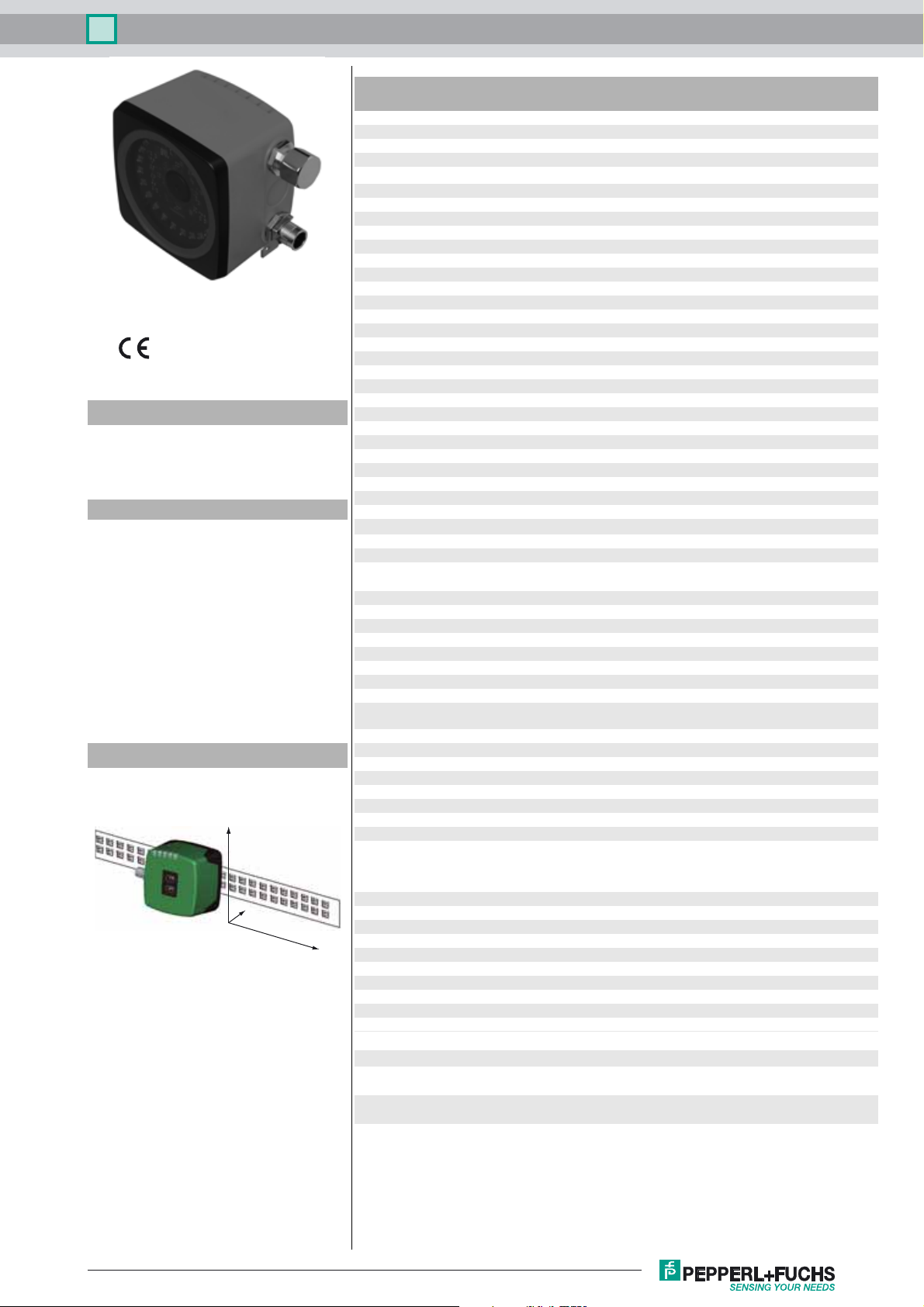
Optical reading head PCV80S-F200-SSI-V19
Technical data
General specifications
Passage speed v ≤ 12.5 m/s
Measuring range max. 10000 m
Model Number
PCV80S-F200-SSI-V19
Read head for incident light positioning
system
Features
•SSI interface
• Non-contact positioning on Data
Matrix code tape
• Mechanically rugged: no wearing
parts, long operating life, maintenance-free
• High resolution and precise positioning, especially for facilities
with curves and switch points as
well as inclines and declines.
• Travel range s up to 1 0 km, in X and
Y direction
Diagrams
Coordinates
Y
Z
X
Light type Integrated LED lightning (red)
Scan rate
Read distance 80 mm
Depth of focus ± 15 mm
Reading field 40 mm x 25 mm
Ambient light limit 100000 Lux
Resolution ± 0.1 mm
Nominal ratings
Camera
Type CMOS , Global shutter
Processor
Clock pulse frequency 600 MHz
Speed of computation 4800 MIPS
Functional safety related parameters
MTTFd 87 a
Mission Time (T
Diagnostic Coverage (DC) 0 %
Indicators/operating means
LED indicator 7 LEDs (communication, alignment aid, status information)
Electrical specifications
Operating voltage U
No-load supply current I
Power consumption P
Interface 1
Interface type SSI interface
Data output code Gray code, binary code , programmable
Monoflop time Tm = 10 µs
Clock frequency 100 ... 1000 kHz
Query cycle time ≥ 1 ms
Pause time tp ≥ 20 µs
Interface 2
Interface type USB (serial comport)
Protocol 8E1
Transfer rate 38.4 ... 460.8 kBit/s
Input
Input type 1 to 2 functional inputs , programmable
Input impedance 26 kΩ
Output
Output type 1 to 2 switch outputs , PNP , programmable , short-circuit
Switching voltage Operating voltage
Switching current 150 mA each output
Standard conformity
Emitted interference EN 61000-6-4:2007+A1:2011
Noise immunity EN 61000-6-2:2005
Shock resistance EN 60068-2-27:2009
Vibration resistance EN 60068-2-6:2008
Ambient conditions
Operating temperature 0 ... 60 °C (32 ... 140 °F)
Storage temperature -25 ... 85 °C (-13 ... 185 °F)
Relative humidity 90 % , noncondensing
Mechanical specifications
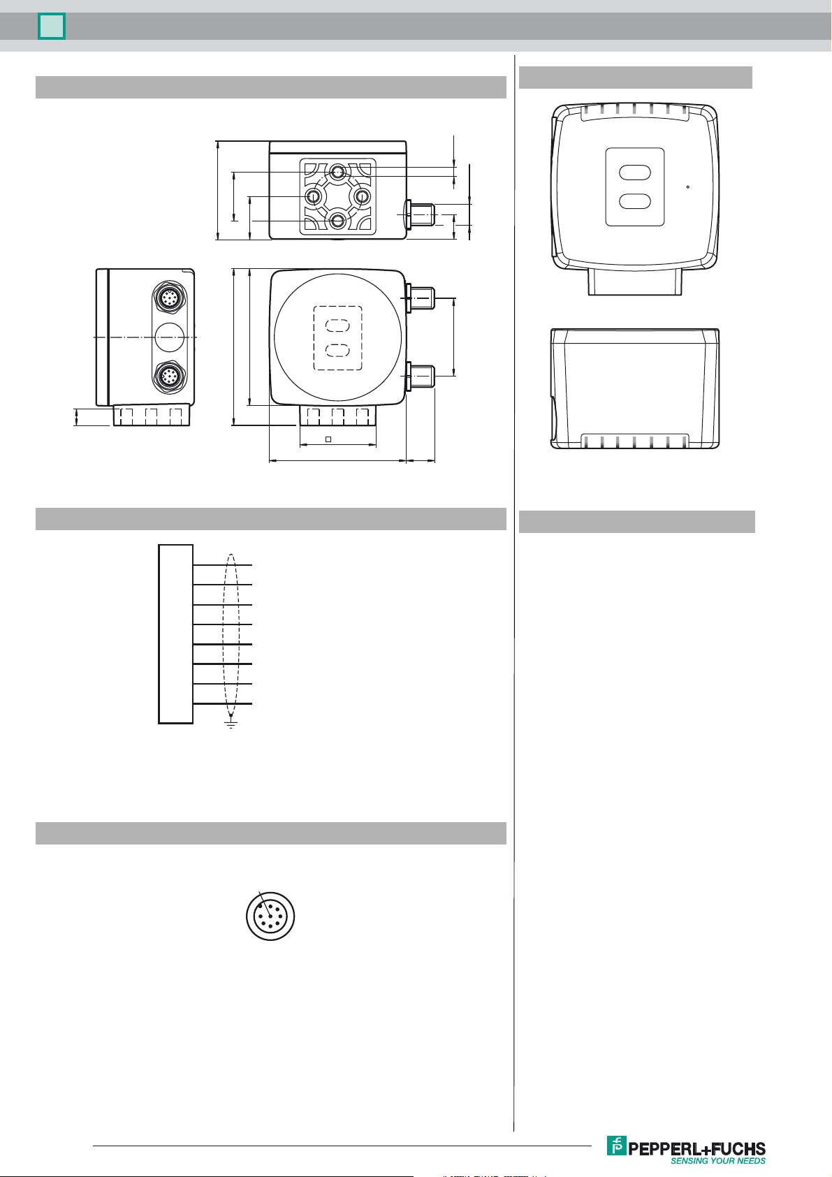
Connection type 8-pin, M12 x 1 connector
Housing width 70 mm
Housing height 70 mm
Degree of protection IP67
Material
Housing PC/ABS
Mass approx. 160 g
) 43 a
M
B
0
0
-1
100 s
15 ... 30 V DC , PELV
max. 200 mA
3 W
double request possible, if t
protected
-20 ... 60 °C (-4 ... 140 °F)
On request, expandable to -25 °C
(noncondensing; prevent icing on the lens!)
≤ 10 µs
p
Release date: 2017-03-24 13:12 Date of issue: 2017-03-24 236862_eng.xml
Refer to “General Notes Relating to Pepperl+Fuchs Product Information”.
Approvals and certificates
UL approval cULus Listed, General Purpose, Class 2 Power Source,
CCC approval CCC approval / marking not required for products rated ≤36
Type 1 enclosure
V
1
Optical reading head PCV80S-F200-SSI-V19
Dimensions
9
Additional Information
4 x M6
51
ø 25
22
7
1
2
6
3
8
5
4
1
70
80
3
2
4
8
1
5
7
6
2
M12 x 1
12
40
38.5
70 14.5
ADJUST
CONFIG
COM SERVICE
1
2
SSI DATA / CONFIG
OUT2 / ADJ Y
PWR / ADJ
ERR / NO CODE
OUT3 / ADJ Z
INTERNAL
LED 1 2 3 4 5 6 7
DIAGNOSTIC
Electrical Connection
Pinout
Accessories
V19-G-ABG-PG9
1
2
3
4
5
6
7
8
OUT 2 / IN 2
+ UB
Data +
Data -
CLK+
CLK-
GND
OUT 3 / IN 3
8
2
1
7
6
Female connector, M12, 8-pin, shielded,
field attachable
V19-G-ABG-PG9-FE
Female connector, M12, 8-pin, shielded,
field attachable
PCV-KBL-V19-STR-USB
USB cable unit with power supply
PCV-LM25
Marker head for 25 mm code tape
PCV-MB1
Mounting bracket for PCV* read head
PCV-AG80
Alignment guide for PCV80-* read head
Vision Configurator
Operating software for camera-based
sensors
53
4
General
The PCV… reading head is part of the positioning system in the method for measurement by Pepperl+Fuchs. It
consists of a camera module and an integrated illumination unit among other things. The reading head detects position marks, which are put on an adhesive code band in the form of Data Matrix code. The mounting of the code
band is as a rule stationary on a firm part of the plant (elevator shaft, overhead conveyor mounting rails…); that of
the reading head is parallel on the moving "vehicle" (elevator car, overhead conveyor chassis…).
Mounting and commissioning
Mount the reading head such that its optical surface captures the optimal read distance to the code band (see Tech-
2
Refer to “General Notes Relating to Pepperl+Fuchs Product Information”.
Release date: 2017-03-24 13:12 Date of issue: 2017-03-24 236862_eng.xml

Optical reading head PCV80S-F200-SSI-V19
nical Data). The stability of the mounting and the guidance of the vehicle must be provided such that the depth of field of the reading head is not closed during operation.
All reading heads can be optimally customized by parameterization for specific requirements.
Displays and Controls
The PCV... reading head allows visual function check and fast diagnosis with 7 indicator LEDs. The reading head has 2 buttons on the reverse of the device to activate the
alignment aid and parameterization mode.
LEDs
LED Color Label Meaning
1 Yellow COM USB interface, communication active
2 Green/red PWR/ADJ
3 Yellow SSI DATA/CONFIG Data flow on SSI interface / configuration
4 Yellow OUT2/ADJ Y Output 2, Alignment aid Y
5 Yellow OUT3/ADJ Z Output 3, Alignment aid Z
6,7 red/green/yellow INTERNAL
ERR/NO CODE
DIAGNOSTICS
Data protocol
12345678 9 101112131415161718 19 20 21 22 23 24 25
Data XP21 XP20 XP19 XP18 XP17 XP16 XP15 XP14 XP13 XP12 XP11 XP10 XP9 XP8 XP7 XP6 XP5 XP4 XP3 XP2 XP1 XP0 Out Wrn Err
MSB LSB Status bits
Position data is coded in XP0 ... XP21 (MSB first)
Meaning of the status bits
Out Err Wrn Meaning
X X 1 reserved
X 1 X Error, error code in XP0 ... XP21
1 X X No codes in read window (XP0 ... XP21 = 0)
Error codes
Error code Meaning
1 reverse reading head orientation (180° contorted)
2 position error: unsecure position codes in reading window
>1000 internal error
External parameterization
For external parameterization you require the parameterization code as Data Matrix with the desired reading head parameters. Data Matrix code cards for step-by-step external
parameterization are printed in the reading heads operating instructions.
Parameterization is only possible within 10 minutes of switching on the reading head. If a button is pressed after 10 minutes subsequent to switching on, there is visual signaling
via the LEDs (LED1, yellow/LED2, red/LED3, yellow/LED4, yellow/LED5, yellow flash for 2 seconds)
• The switchover from normal operation to parameterization mode is via button 2 on the reverse of the reading head. Button 2 must be pressed for more than 2 seconds.
LED3 now flashes.
Note:Parameterization mode automatically ends after 1 minute of inactivity. The reading head returns to normal operation and works with unchanged settings.
• Place the parameterization code in the view of the camera module. After recognition of the parameterization code, the green LED2 lights up for 1s. In the event of an
invalid parameterization code, the red LED2 lights up for 2 s.
• A short press on button 2 ends the parameterization mode and the changed parameters are not stored volatile in the reading head.
Alignment aid for the Y and Z coordinates
The activation of the alignment aid is only possible within 10 minutes of switching on the reading head. The switchover from normal operation to “alignment aid operating mode
is via button 1 on the reverse of the reading head.
• Press the button 1 for longer than 2 s. LED2 flashes green for a recognized code band. LED2 flashes red for an unrecognized code band.
• Z coordinate
: If the distance of the camera to the code band too small, the yellow LED5 lights up. If the distance of the camera to the code band too large, the yellow
LED5 lights up. Within the target range, the yellow LED5 flashes at the same time as the green LED2.
• Y coordinate
: If the optical axis of the camera is too deep in relation to the middle of the code band, the yellow LED4 lights up. If the optical axis is too high, the yellow
LED4 extinguishes. Within the target range, the yellow LED4 flashes at the same time as the green LED2.
• A short press on button 1 ends the alignment aid and the reading head changes to normal operation.
Code recognized/not recognized, Error
Internal diagnostics
Release date: 2017-03-24 13:12 Date of issue: 2017-03-24 236862_eng.xml
Refer to “General Notes Relating to Pepperl+Fuchs Product Information”.
3
 Loading...