

Pepperl Fuchs PCV100-F200-SSI-V19 Data Sheet
Optical reading head PCV100-F200-SSI-V19
Technical data
General specifications
Passage speed v ≤ 8 m/s
Measuring range max. 10000 m
Light type Integrated LED lightning (red)
Read distance 100 mm
Depth of focus ± 20 mm
Reading field 50 mm x 30 mm
Ambient light limit 100000 Lux
Resolution ± 0.1 mm
Nominal ratings
Camera
Type CMOS , Global shutter
Processor
Clock pulse frequency 600 MHz
Speed of computation 4800 MIPS
Functional safety related parameters
MTTFd 87 a
Mission Time (TM) 43 a
Diagnostic Coverage (DC) 0 %
Indicators/operating means
LED indicator 7 LEDs (communication, alignment aid, status information)
Model Number
PCV100-F200-SSI-V19
Read head for incident light positioning
system
Features
•SSI interface
• Non-contact positioning on Data
Matrix code tape
• Mechanically rugged: no wearing
parts, long operating life, maintenance-free
• High resolution and precise positioning, especially for facilities
with curves and switch points as
well as inclines and declines.
• Travel ran g es up t o 10 km, in X an d
Y direction
Diagrams
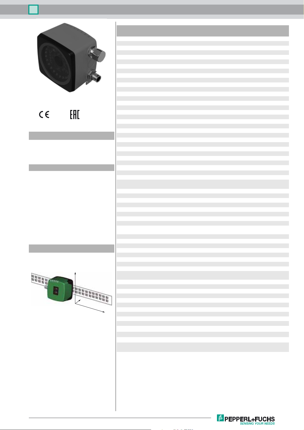
Coordinates
Y
Z
X
Electrical specifications
Operating voltage U
No-load supply current I
Power consumption P
Interface 1
Interface type SSI interface
Data output code Gray code, binary code , programmable
Monoflop time T
Clock frequency 100 ... 1000 kHz
Query cycle time ≥ 3 ms
Pause time tp ≥ 20 µs
Interface 2
Interface type USB (serial comport)
Protocol 8E1
Transfer rate 38.4 ... 460.8 kBit/s
Input
Input type 1 to 2 functional inputs , programmable
Input impedance ≥ 27 kΩ
Output
Output type 1 to 2 switch outputs , PNP , programmable , short-circuit
Switching voltage Operating voltage
Switching current 150 mA each output
Standard conformity
Emitted interference EN 61000-6-4:2007+A1:2011
Noise immunity EN 61000-6-2:2005
Shock resistance EN 60068-2-27:2009
Vibration resistance EN 60068-2-6:2008
Ambient conditions
Operating temperature 0 ... 60 °C (32 ... 140 °F) , -20 ... 60 °C (-4 ... 140 °F)
Storage temperature -20 ... 85 °C (-4 ... 185 °F)
Relative humidity 90 % , noncondensing
Mechanical specifications
Connection type 8-pin, M12 x 1 connector
Housing width 70 mm
Housing height 70 mm
Degree of protection IP67
Material
Housing PC/ABS
Mass approx. 160 g
B
0
0
15 ... 30 V DC , PELV
max. 200 mA
3 W
= 10 µs
m
double request possible, if t
protected
(noncondensing; prevent icing on the lens!)
≤ 10 µs
p
Release date: 2017-03-24 13:12 Date of issue: 2017-03-24 236998_eng.xml
Refer to “General Notes Relating to Pepperl+Fuchs Product Information”.
Approvals and certificates
EAC conformity TR CU 020/2011
UL approval cULus Listed, General Purpose, Class 2 Power Source,
CCC approval CCC approval / marking not required for products rated ≤36
Type 1 enclosure
V
1
Optical reading head PCV100-F200-SSI-V19
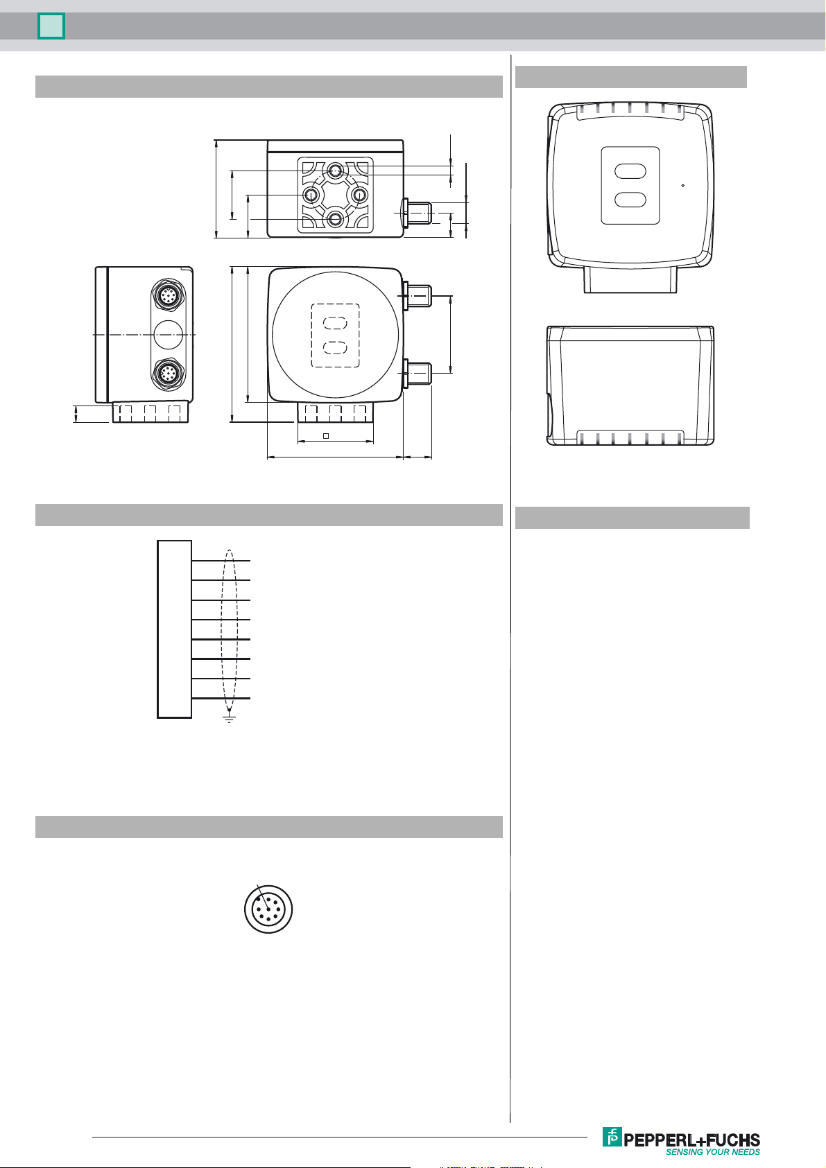
Dimensions
9
Additional Information
4 x M6
51
ø 25
22
7
1
2
6
3
8
5
4
1
70
80
3
2
4
8
1
5
7
6
2
M12 x 1
12
40
38.5
70 14.5
ADJUST
CONFIG
COM SERVICE
1
2
SSI DATA / CONFIG
OUT2 / ADJ Y
PWR / ADJ
ERR / NO CODE
OUT3 / ADJ Z
INTERNAL
LED 1 2 3 4 5 6 7
DIAGNOSTIC
Electrical Connection
Pinout
Accessories
V19-G-ABG-PG9
1
2
3
4
5
6
7
8
OUT 2 / IN 2
+ UB
Data +
Data -
CLK+
CLK-
GND
OUT 3 / IN 3
8
2
1
7
6
Female connector, M12, 8-pin, shielded,
field attachable
V19-G-ABG-PG9-FE
Female connector, M12, 8-pin, shielded,
field attachable
PCV-KBL-V19-STR-USB
USB cable unit with power supply
PCV-SC12
Grounding clip for PCV system
PCV-LM25
Marker head for 25 mm code tape
PCV-MB1
Mounting bracket for PCV* read head
PCV-AG100
Alignment guide for PCV100-* read head
Vision Configurator
Operating software for camera-based
sensors
53
4
General
The PCV… reading head is part of the positioning system in the method for measurement by Pepperl+Fuchs. It
consists of a camera module and an integrated illumination unit among other things. The reading head detects position marks, which are put on an adhesive code band in the form of Data Matrix code. The mounting of the code
band is as a rule stationary on a firm part of the plant (elevator shaft, overhead conveyor mounting rails…); that of
the reading head is parallel on the moving "vehicle" (elevator car, overhead conveyor chassis…).
Mounting and commissioning
Mount the reading head such that its optical surface captures the optimal read distance to the code band (see Tech-
2
Refer to “General Notes Relating to Pepperl+Fuchs Product Information”.
Release date: 2017-03-24 13:12 Date of issue: 2017-03-24 236998_eng.xml
 Loading...