

Pepperl Fuchs RM-GXP1100-19S, RM-GXP1200-19S, PC-GXP1100-19S, PC-GXP1200-19S Instruction manual
Page 1
VisuNet GXP
RM-GXP1100-19S
RM-GXP1200-19S
PC-GXP1100-19S
PC-GXP1200-19S
Manual
Page 2

With regard to the supply of products, the current issue of the following document is applicable: The
General Terms of Delivery for Products and Services of the Electrical Industry, published by the Central
Association of the Electrical Industry (Zentralverband Elektrotechnik und Elektroindustrie (ZVEI) e.V.)
in its most recent version as well as the supplementary clause: "Expanded reservation of proprietorship"
Worldwide
Pepperl+Fuchs Group
Lilienthalstr. 200
68307 Mannheim
Germany
Phone: +49 621 776 - 0
E-mail: info@de.pepperl-fuchs.com
North American Headquarters
Pepperl+Fuchs Inc.
1600 Enterprise Parkway
Twinsburg, Ohio 44087
USA
Phone: +1 330 425-3555
E-mail: sales@us.pepperl-fuchs.com
Asia Headquarters
Pepperl+Fuchs Pte. Ltd.
P+F Building
18 Ayer Rajah Crescent
Singapore 139942
Phone: +65 6779-9091
E-mail: sales@sg.pepperl-fuchs.com
https://www.pepperl-fuchs.com
Page 3

VisuNet GXP
Contents
1 Introduction................................................................................................................ 4
1.1 Content of this Document............................................................................. 4
1.2 Target Group, Personnel ............................................................................... 4
1.3 Symbols Used ................................................................................................ 5
2 Product Description ..................................................................................................6
2.1 Overview......................................................................................................... 6
2.2 Technical Specifications ............................................................................... 9
2.3 Dimensions................................................................................................... 13
2.4 Disposal........................................................................................................ 15
3 Mechanical Installation ........................................................................................... 16
3.1 General Installation Requirements ............................................................ 16
3.2 Installation Tools.......................................................................................... 16
3.3 System Installation ......................................................................................16
3.3.1 Preparation for System Installation................................................... 16
3.3.2 Preparing the GXP Panel/Housing................................................... 18
3.3.3 Preparing the StandardLine Pedestal .............................................. 20
3.3.4 Attaching the Pedestal to the Housing ............................................. 24
3.3.5 Opening the Housing ....................................................................... 27
3.3.6 Grounding the Housing to the Pedestal ........................................... 28
3.3.7 Installation of Ferrite Core ................................................................ 31
3.3.8 Mounting the Keyboard.................................................................... 32
3.3.9 Mounting the Scanner Holder to the AG1 Housing .......................... 34
3.3.10 Installing the Handheld 1-D/2-D Code Reader................................. 40
3.4 Replacing a VisuNet EX1 with the 19-Inch VisuNet GXP..........................46
3.4.1 Removing VisuNet EX1 from AG1 Housing...................................... 47
3.4.2 Installing VisuNet GXP into AG1 Housing ........................................ 49
3.5 Panel Mount Installation .............................................................................52
3.6 Wall Mount Installation................................................................................ 55
4 Appendix .................................................................................................................. 57
4.1 Accessories.................................................................................................. 57
4.2 UL Control Drawing ..................................................................................... 58
2020-09
3
Page 4
VisuNet GXP
Introduction
1 Introduction
1.1 Content of this Document
This document contains information that you need in order to use your product throughout the
applicable stages of the product life cycle. These can include the following:
• Product identification
• Delivery, transport, and storage
• Mounting and installation
• Commissioning and operation
• Maintenance and repair
• Troubleshooting
• Dismounting
• Disposal
Note
This document does not substitute the instruction manual.
Note
For full information on the product, refer to the instruction manual and further documentation on
the Internet at www.pepperl-fuchs.com.
The documentation consists of the following parts:
• Present document
• Instruction manual
• Datasheet
Additionally, the following parts may belong to the documentation, if applicable:
• EU-type examination certificate
• EU declaration of conformity
• Attestation of conformity
• Certificates
• Control drawings
• Additional documents
1.2 Target Group, Personnel
Responsibility for planning, assembly, commissioning, operation, maintenance, and dismounting lies with the plant operator.
Only appropriately trained and qualified personnel may carry out mounting, installation, commissioning, operation, maintenance, and dismounting of the product. The personnel must have
read and understood the instruction manual and the further documentation.
Prior to using the product make yourself familiar with it. Read the document carefully.
4
2020-09
Page 5
VisuNet GXP
Introduction
1.3 Symbols Used
This document contains symbols for the identification of warning messages and of informative
messages.
Warning Messages
You will find warning messages, whenever dangers may arise from your actions. It is mandatory
that you observe these warning messages for your personal safety and in order to avoid property damage.
Depending on the risk level, the warning messages are displayed in descending order as follows:
Danger!
This symbol indicates an imminent danger.
Non-observance will result in personal injury or death.
Warning!
This symbol indicates a possible fault or danger.
Non-observance may cause personal injury or serious property damage.
Caution!
This symbol indicates a possible fault.
Non-observance could interrupt the device and any connected systems and plants, or result in
their complete failure.
Informative Symbols
Note
This symbol brings important information to your attention.
Action
This symbol indicates a paragraph with instructions. You are prompted to perform an action or
a sequence of actions.
2020-09
5
Page 6

VisuNet GXP
Product Description
2 Product Description
2.1 Overview
The Pepperl+Fuchs VisuNet Remote Monitors GXP RM-GXP1100-19S*/RM-GXP1200-19S*
and PC-GXP-1100-19S*/PC-GXP-1200-19S* are ATEX/IECEx certified, UL listed devices
intended for use in potentially explosive atmospheres, such as Zones 1/21, 2/22 and Class I
Div. 2, Class II Div. 2, and Class III.
The VisuNet GXP serves as a thin client- or PC-based operator workstation that uses standard
Ethernet technology to transmit process information from a process control or manufacturing
execution system into hazardous areas.
The assembly consists of several core devices that can be exchanged by the customer:
• The display units DPU1100-* and DPU1200-* are display panels with optional 10-finger
multi-touch sensors. The displays and touch-sensors are optically bonded with the hardened front glass.
• The thin client units TCU1100-* and TCU1200-* are computing units running the latest
Pepperl+Fuchs RM Shell 5.x firmware. They allow connectivity to various host systems in
the safe area using standard Ethernet technology. The computing units PCU1100-* and
PCU1200-* run an open Microsoft® Windows® operating system, allowing installation of
any software, such as SCADA packages.
• The power supply units PSU1100-* and PSU1200-* provide the above-listed devices with
24 V DC power. They are available as DC and AC versions.
As the standard mounting option, a bezel is available that allows the panel to be mounted into a
system housing or cabinet that needs to be ordered separately. The panel can also be flushmounted into a cabinet from behind.
2020-09
6
Page 7
VisuNet GXP
1
2
3
4
Product Description
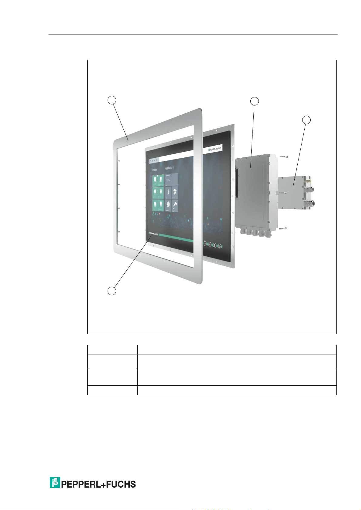
VisuNet GXP Panel Components
Figure 2.1 VisuNet GXP panel components
1 Bezel for housing and panel mounting
2 Computing unit (TCU or PCU): processor, SSD and memory, Ex circuits,
interface modules
3 Power supply unit: DC or AC option, backpacked (panel-mount) or stand-
alone (in system enclosure)
4 Display unit: display, touch screen, hardened front glass
2020-09
7
Page 8
VisuNet GXP
Product Description
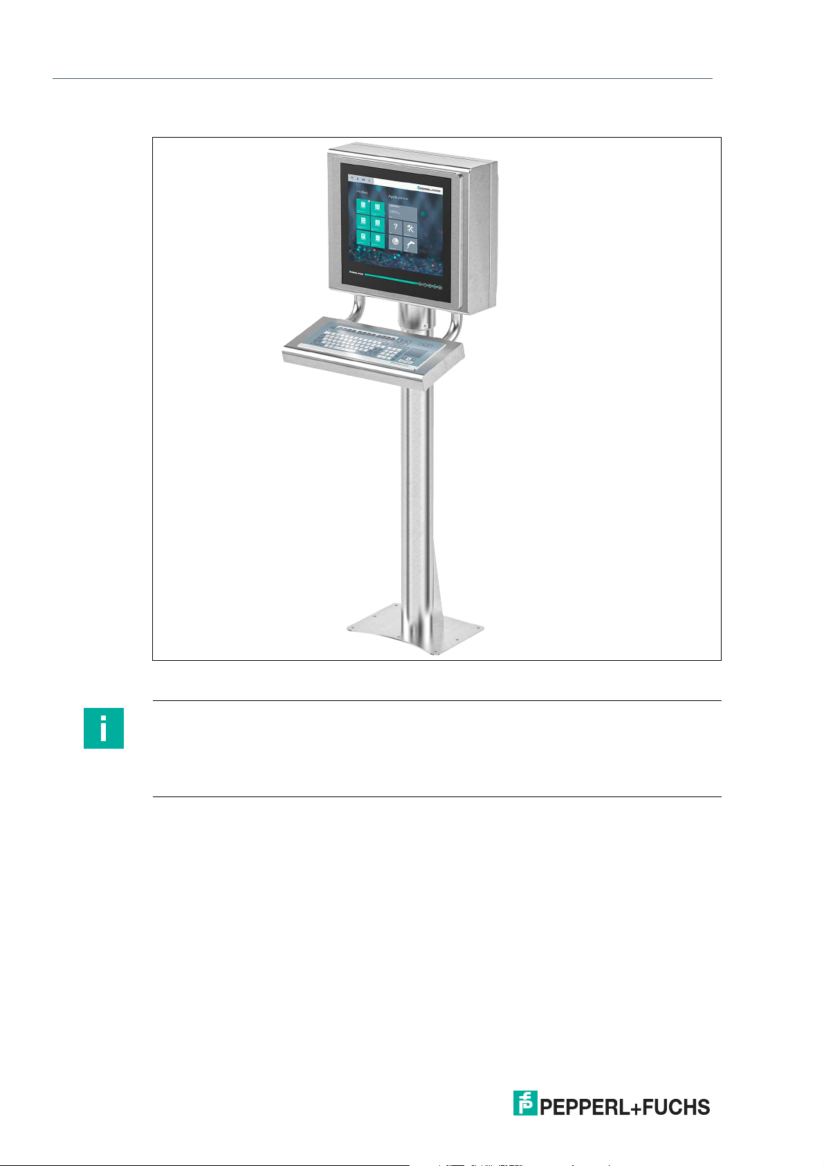
VisuNet GXP Pedestal Mounted with Keyboard/Mouse
Figure 2.2 VisuNet GXP system mounted in AG1 Housing with Pedestal5 -1458-* and EXTA2
keyboard/mouse (ordered separately)
Note
For a description of the product model nomenclature, see the VisuNet GXP PC or VisuNet GXP
RM product datasheets at www.pepperl-fuchs.com.
For more mounting options and information, see the datasheet "Mounting Options
'StandardLine' and 'BasicLine'".
2020-09
8
Page 9
VisuNet GXP
Product Description
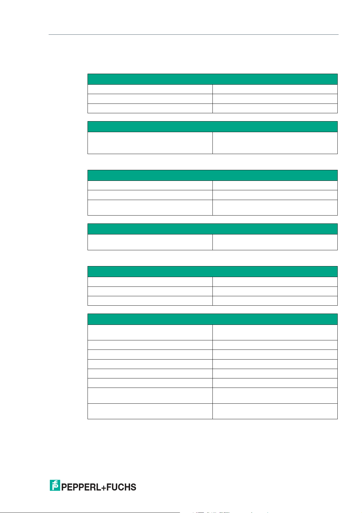
2.2 Technical Specifications
Technical Data RM-GXP*
Hardware
Processor Intel® Atom™ Apollo Lake E3930
RAM 4 GB RAM
Mass storage 32 GByte industrial grade MLC SSD
Software
Operating system VisuNet RM Shell 5.x (based on Microsoft®
Technical Data PC-GXP*
Hardware
Processor Intel® Atom™ Atom Apollo Lake E3940
RAM 8 GB
Mass storage 240 GByte industrial grade SSD
Windows® 10 IoT Enterprise 2019 LTSC
(x64))
Optional: 480 GByte SSD
Software
Operating system Microsoft® Windows® 10 IoT Enterprise 2019
LTSC (x64)
Technical Data RM-GXP* and PC-GXP*
Supply
Power consumption
AC 115/230 V AC, 0.4 ... 0.7 A, 50/60 Hz
DC 18 ... 36 V DC , 1.5 ... 3 A
Display
Type: Liquid Crystal Display (LCD) with LED back-
Screen diagonal: 48.26 cm (19 inch)
Resolution: 1280 x 1024 (SXGA) , Aspect ratio 5:4
Color depth: 24 bit (16.7 M) color
Contrast: 1000:1
Brightness: 450 cd/m2
Reading angle: horizontal: 170°
Life span: back lamp life: 50.000 hrs typical half life, at 25
light
vertical: 160°
°C (77 °F)
2020-09
9
Page 10
VisuNet GXP
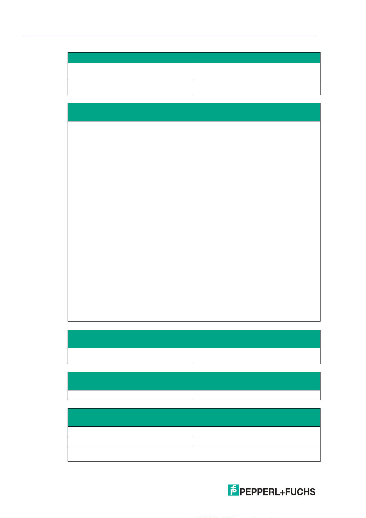
Product Description
Input devices
Touchscreen: optional: projective capacitive;
Keyboard: Foil keyboard with different pointing device
Interface
Interface type 1 x Ethernet 100/1000BASE-TX (Ex e) or
10 finger multi-touch, glove friendly
options available (see EXTA2 datasheet)
1 x fiber optic 1000BASE-SX (Multimode) or
1 x fiber optic 1000BASE-LX (Singlemode)
1 x USB 2.0 (Ex e)
2 x USB 1.1 (Ex i; intended for Pepperl+Fuchs
keyboard and mouse)
1 x DC or AC power in (via power supply unit)
Optional:
1 x barcode reader interface Pepperl+Fuchs
Pscan-D/B (Ex i)
"interface 3": 1 x barcode reader interface for
wired 1-D scanners IDM-160-D*, IDM-Z1160-D-* and base station IDMx61-B-* and
IDM-Z1-x61-B-*
"interface 4": 1 x barcode reader interface for
wired 2-D Scanner IDM-Z1-260-D-* (Ex i)
"interface 5": 1 x RS-232 interface with Power
Supply for miscellaneous devices and peripherals (Ex i)
1 x RS-232 (Ex e)
1 x RS-485 (Ex e)
1 x Ethernet 100/1000Base-TX (Ex e)
Bluetooth v4.0, communication distance up to
30 m in open terrain, transmission power +8
dBm, transmission frequency 2.402 ... 2.48
GHz
Electromagnetic compatibility
Directive 2014/30/EU EN 61326-1:2013 (industrial locations)
RoHS
non-Bluetooth products only
10
Directive 2011/65/EU (RoHS) EN 50581:2012-09
Ambient conditions
Operating temperature -20 ... 50 °C (-4 ... 122 °F)
Storage temperature -20 ... 60 °C (-4 ... 140 °F)
Relative humidity 93% at 40°C, non-condensating, according to
EN60068-2-78
2020-09
Page 11
VisuNet GXP
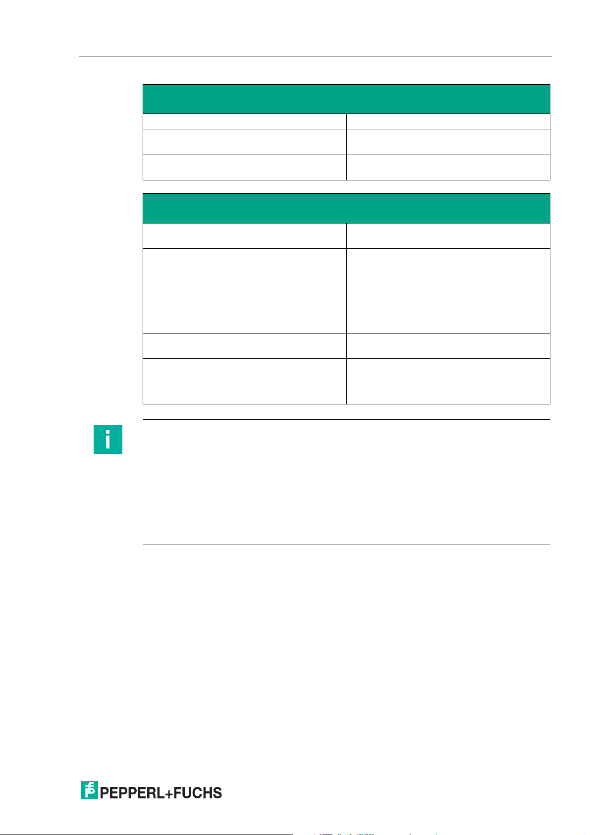
Product Description
Ambient conditions
Altitude Operating altitude max. 2000 m
Shock resistance 18 shocks 15 g , 11 ms all axis, IEC 60068-2-
Vibration resistance 10 ... 150 Hz, +/- 0.075 mm , 1g, 10 cycles per
Mechanical specifications
27
axis according to EN60068-2-6
Degree of protection IP66 (individual components and entire sys-
Material Internal:
Mass panel with DC: 22 kg , panel with AC: 23 kg ,
Dimensions panel with DC: 524 mm x 453 mm x 120 mm
Note
For more technical information, refer to the manuals and instruction manuals of the individual
components:
• Display Units DPU1100-J1* and DPU1200-J2*
• AC Power Supply Units PSU1100-J1-AC-N0 and PSU1200-J2-AC-N0
• DC Power Supply Units PSU1100-J1-DC-N0 and PSU1200-J2-DC-N0
tem with housing)
Panel: anodized aluminum (TCU, PSU), powder coated aluminum (DPU)
External:
Bezel: stainless steel AISI 304 (1.4301)
System housing: stainless steel AISI 304
(1.4301), ground smooth, typical surface
roughness Ra = 1.6 µm
system housing AG1: 19 kg
panel with AC: 524 mm x 453 mm x 137 mm
panel with AG1 housing: 582 mm x 490 mm x
224 mm
• Thin Client Units TCU1100-J1-* and TCU1200-J2-*
• Computing Units PCU1100-J1-* and PCU1200-J2-*
2020-09
11
Page 12
VisuNet GXP
Product Description
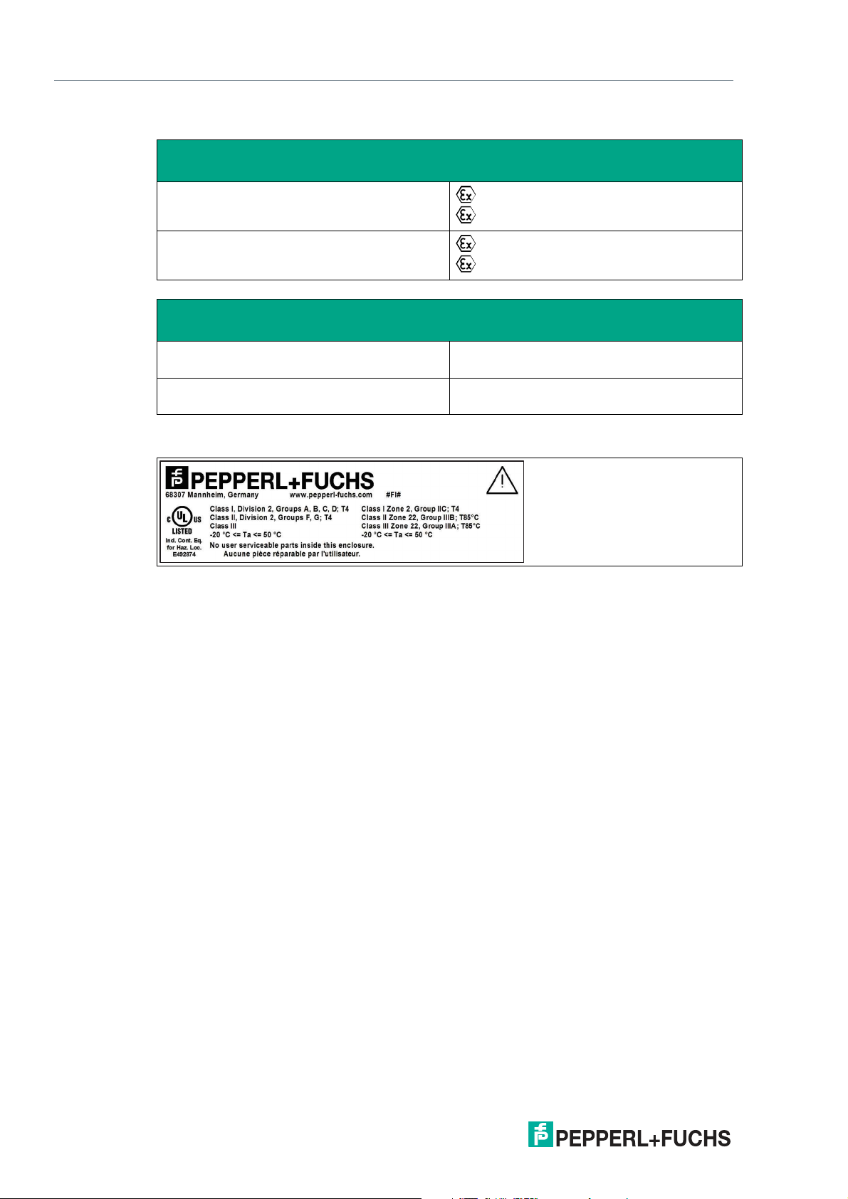
Marking
ATEX
RM-GXP1100-J1-*
RM-GXP1200-J2-*
IECEx
RM-GXP1100-J1-* Ex eb q ib [ib] IIC T4 IP66 Gb
RM-GXP1200-J2-* Ex ec [ib] q IIC T4 IP66 Gc
II 2G Ex eb q ib [ib] IIC T4 IP66 Gb
II 2D Ex tb [ib] IIIC T85°C IP66 Db
II 3G Ex ec [ib] q IIC T4 IP66 Gc
II 3D Ex tc [ib] IIIC T85 °C IP66 Dc
Ex tb [ib] IIIC T85°C IP66 Db
Ex tc [ib] IIIC T85 °C IP66 Dc
UL Marking
12
2020-09
Page 13
VisuNet GXP
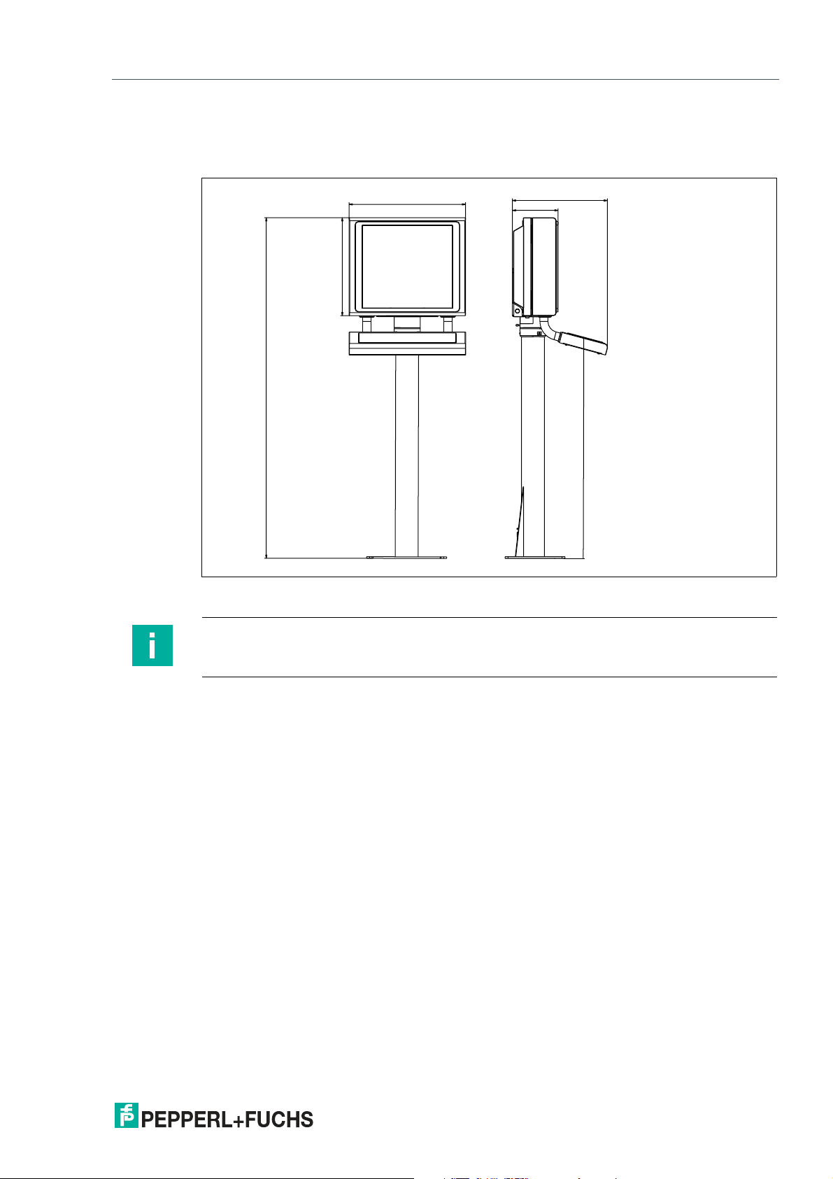
582
490
1702
228
475
1100
Product Description
2.3 Dimensions
Dimensions with AG1 Housing and Pedestal
Figure 2.3 Dimensions with StandardLine Pedestal5-1458-Fix and EXTA2 keyboard/mouse—sample
configuration
Note
Keyboard/mouse and pedestal are ordered separately.
2020-09
13
Page 14
VisuNet GXP
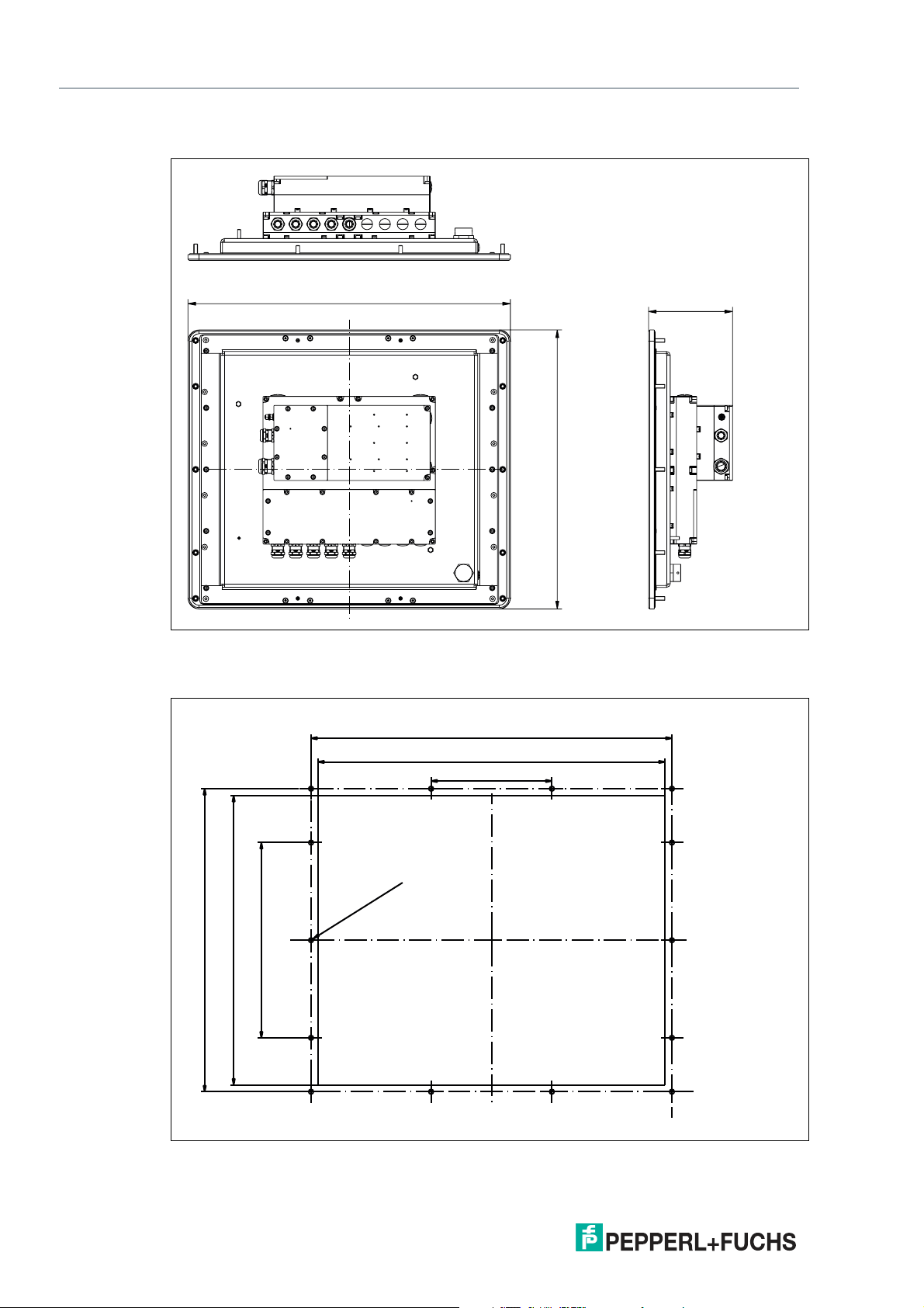
524
137
453
499
480
167
419
400
270
Ø 6.5
± 0.5 (14 x)
Product Description
Panel Dimensions with Bezel
Panel Cut-Out Dimensions
Cut-out dimensions: 480 x 400 mm. For more information, see chapter 3.5.
14
2020-09
Page 15
VisuNet GXP
490
582
583
62
532
285
686
413
Product Description
Wall Mount Dimensions
Figure 2.4 Wall mount dimensions with additional wall brackets (#198768)
2.4 Disposal
Follow all local and any other requirements for disposing of electronic equipment. When disposing of any system component, mark VOID across all certification labels.
2020-09
15
Page 16
VisuNet GXP
Mechanical Installation
3 Mechanical Installation
3.1 General Installation Requirements
Observe the following requirements when installing the system components.
• The equipment must be installed by competent personnel in accordance with the instruc-
tions. National laws and regulations must be observed.
• The building installation must provide a 20 A overcurrent protection.
• The installer must make a readily accessible disconnect device available.
• The safety of any system incorporating the power supply unit is the responsibility of the
assembler of the system.
3.2 Installation Tools
• 4-mm and 5-mm torque Allen keys
• Open-ended wrench for cable glands
• Screws for floor or wall mounting. Choose the appropriate screws based on the mounting
conditions.
• Small cable ties
• Side cutters
• Strong adhesive tape, such as duct tape or packing tape
• At least 1 piece of thin, 2.5-m-long wire for pulling cables through the pedestal
Warning!
Risk of injury
Lifting the device on your own may lead to injury.
Do not attempt to lift the device on your own. Use a crane or have another person help you.
3.3 System Installation
3.3.1 Preparation for System Installation
Warning!
Proper installation on the floor
It is the installer's responsibility to select a suitable location with sufficient strength to hold the
equipment. It is the installer's responsibility to select the proper screws based on the installation conditions.
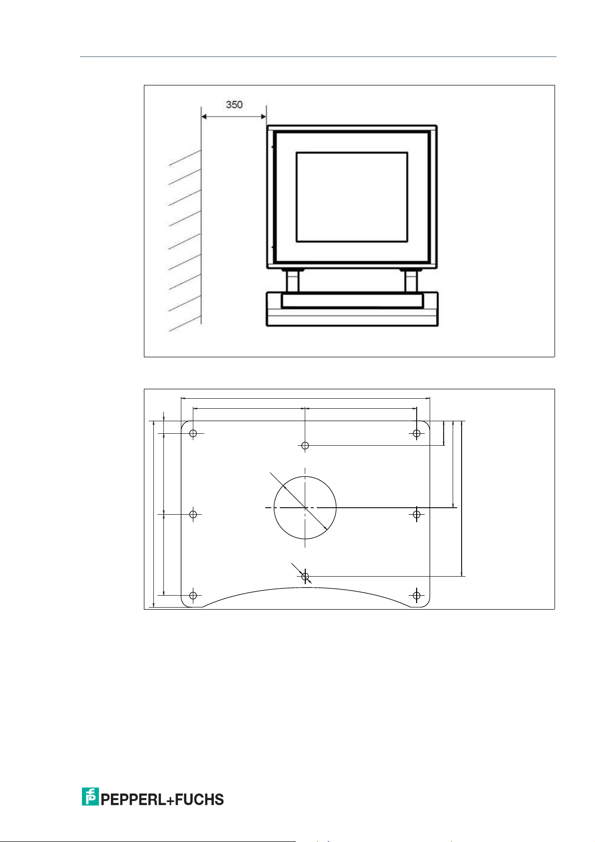
Warning!
Distance between housing and wall
Provide at least 350 mm of space between the housing/pedestal assembly and the left wall.
This is required in order to properly open the housing and connect the GXP components.
16
2020-09
Page 17
VisuNet GXP
400
180 180
300
250
140
130
130
20
40
Ø 100
Ø 10
Mechanical Installation
Figure 3.1 Distance required between housing/pedestal assembly and wall
StandardLine Pedestal Floor-Mount Hole Pattern
2020-09
17
Page 18
VisuNet GXP
071
031
130
170
90
45°
1
0
5°
5°
184
Mechanical Installation
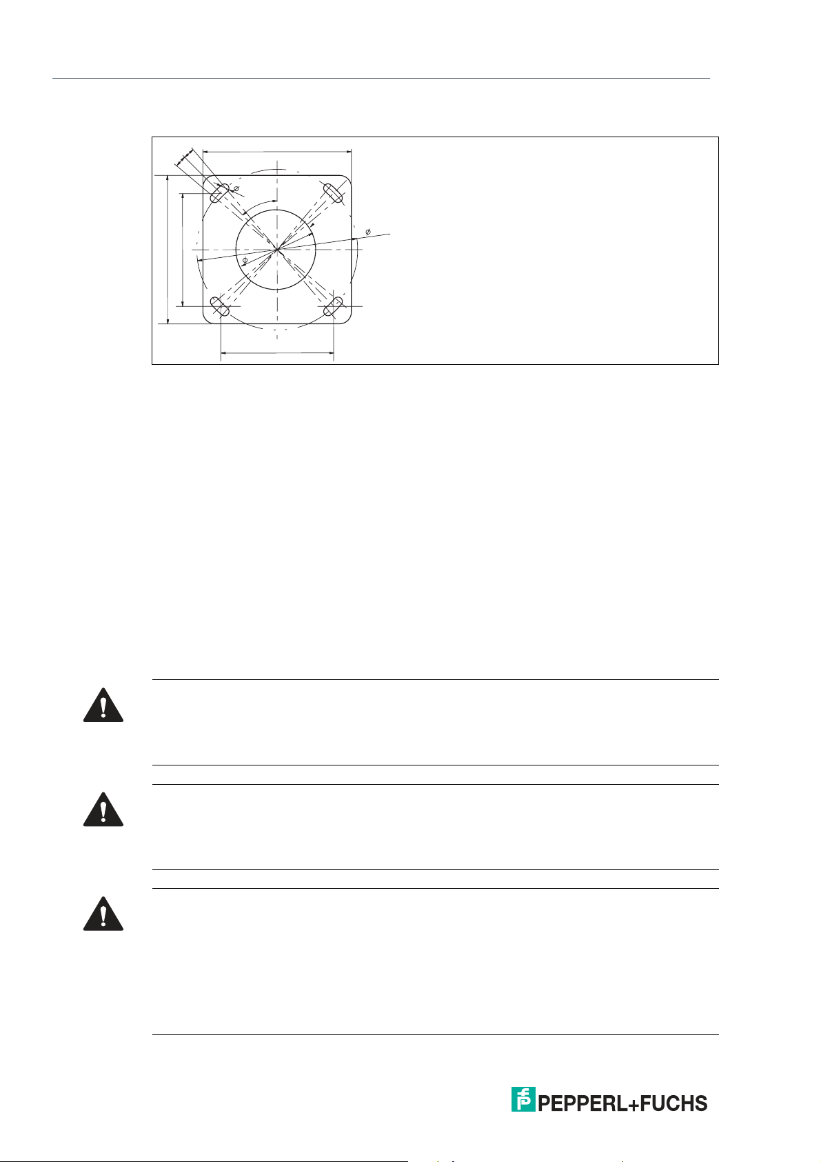
BasicLine Pedestal Floor-Mount Hole Pattern
3.3.2 Preparing the GXP Panel/Housing
The VisuNet GXP comes pre-assembled and consists of the core components display unit,
power supply unit, and thin client unit / power supply unit. If the AG1 housing option is chosen,
the panel is pre-mounted in the housing.
Included with Delivery
• 1 x pre-assembled VisuNet RM-GXP or PC-GXP panel (option: panel-mounted into AG1
housing)
• 2 x protective tubes
• 1 x Ferrite ring and Ferrite key
• Screws for housing
Items Ordered Separately
• Pedestal that is compatible with AG1 housing (StandardLine or BasicLine pedestal)
• Optional EXTA2-* keyboard
Warning!
Risk of injury
Handling the devices with bare hands may cut fingers, hands, or wrists.
Wear gloves at all times during the installation process.
Warning!
Risk of injury
Lifting the GXP housing on your own may cause injury.
Do not attempt to lift the device on your own. Use a crane or have another person help you.
Warning!
Danger resulting from scratched display unit screen
Scratches on a display unit front screen weaken the glass structure and may result in broken
glass. Explosion protection is no longer ensured if a display unit with a scratched screen is
used.
NEVER use a display unit with a scratched front screen in a hazardous area. If the surface is
damaged in any way, return the display unit to Pepperl+Fuchs at once and replace it with a new
one.
2020-09
18
Page 19

VisuNet GXP
Mechanical Installation
Preparing the Housing
1.
Remove the box and leave the protective foam blocks on the housing. Save the uncollapsed
box for further mounting steps.
2.
Wrap strong adhesive tape around the foam blocks to hold them onto the housing and protect
the components during mounting.
3.
Place the housing face down on a flat surface.
4.
Remove and discard the screws from the bottom of the housing.
2020-09
19
Page 20

VisuNet GXP
1
2
3
Mechanical Installation
3.3.3 Preparing the StandardLine Pedestal
A variety of pedestals are available for floor mounting. For a complete list of available mounting
options, see the mounting options datasheet. Pedestals are shipped with an attached protective earth (PE) wire and screws for mounting the VisuNet GXP AG1 housing to the pedestal: 6 x
M8 countersunk screws and 2 x M6 countersunk screws.
StandardLine Pedestal
1 Pre-installed PE wire
2 Top cable opening
3 Cable glands
2020-09
20
Page 21

VisuNet GXP
1
2
3
4
Mechanical Installation
Bottom of Pedestal
1 PE stud
2 M25 opening
3 M20 opening
4 M20 plug
Warning!
Connection to the PE stud
Connection to the PE stud is mandatory.
Opening Size Wrench Size Cable Diameter Torque
M20 24 mm 7 ... 13 mm 12 Nm
M25 29 mm 9 ... 17 mm
2020-09
21
Page 22

VisuNet GXP
Mechanical Installation
Preparing the Pedestal for Connection to the GXP Housing
1.
Remove the cable glands at the bottom of the pedestal.
2.
Feed the pull wire (thin, 2.5-m-long wire for pulling cables through pedestal) through the top of
the pedestal and out the appropriate cable entry.
3.
Put the gland nut and ferrule of the cable gland on the cable and slide them a few meters down
the length of the cable away from the pedestal. Keep the nut and ferrule on the cable in order to
tighten them in a later installation step.
4.
Attach the cable to the pull wire.
22
2020-09
Page 23

VisuNet GXP
Mechanical Installation
5.
Pull the cable through the cable entry and out the top of the pedestal.
6.
Pull the cable through the pedestal so that 50 cm of cable is hanging out of the top of the
pedestal.
7.
Repeat the preceding steps for each cable that must be routed through the pedestal.
2020-09
23
Page 24

VisuNet GXP
Mechanical Installation
3.3.4 Attaching the Pedestal to the Housing
Warning!
Risk of injury
Lifting the GXP housing on your own may cause injury.
Do not attempt to lift the device on your own. Use a crane or have another person help you.
Mounting the Pedestal
1.
Rest the pedestal on the box that the GXP housing was shipped in. Position the pedestal and
box behind the housing.
2.
Slide the cable ends from the top of the pedestal through the openings in the bottom of the
housing.
24
Warning!
Damage to cables
The cables may become damaged if they are pinched between the pedestal
and the housing.
Ensure that the cables do not get caught between the pedestal and housing
during the mounting process.
3.
Align the mounting holes on the top of the pedestal with the mounting holes on the back of the
housing.
2020-09
Page 25

VisuNet GXP
Mechanical Installation
4.
Tighten the 6 x M8 screws in a criss-cross pattern to 20 Nm.
5.
Tighten the 2 x M6 screws to 12 Nm.
2020-09
25
Page 26

VisuNet GXP
Mechanical Installation
Positioning and Floor-Mounting the GXP
1.
Remove the box from under the pedestal and carefully position the system upright on the floor
with a crane or the help of another person.
26
2.
Mount the pedestal onto the floor using suitable screws.
Warning!
Proper floor mounting
It is the installer's responsibility to select a suitable location with sufficient
strength to hold the equipment. It is the installer's responsibility to select the
proper screws based on the installation conditions.
3.
Remove the protective foam blocks.
4.
Remove the protective plastic film from the screen. This should not be present in a hazardous
location.
Note
For more information on floor mounting, including hole patterns, see see chapter 3.3.1.
Note
The StandardLine pedestal is depicted above. Follow the same steps to mount the VisuNet
GXP with the BasicLine pedestal.
2020-09
Page 27

VisuNet GXP
Mechanical Installation
3.3.5 Opening the Housing
The GXP housing is hinged and opens to the left.
Opening the GXP
Warning!
Risk of Damage and Injury
Opening the GXP housing before the pedestal is mounted onto the floor may
cause the housing and pedestal to tip over.
Mount the pedestal to the floor before opening the GXP housing.
1.
Loosen the 4 screws on the back of the housing.
2.
Gently pull the front side of the housing toward you.
2020-09
27
Page 28

VisuNet GXP
Mechanical Installation
3.
Pull the right side of the housing front away from the back part of the housing.
3.3.6 Grounding the Housing to the Pedestal
Warning!
Customer responsibility to verify grounding path
Check the grounding path after completing system installation.
The AG1 housing comes with a pre-installed PE wire that is connected from the inside-top of
the housing to the inside-back of the housing. The pedestal comes with a pre-installed PE wire
that you must route from the pedestal into the housing (see see chapter 3.3.3).
28
2020-09
Page 29

VisuNet GXP
Mechanical Installation
Connecting the PE Wires
1.
Remove the nuts and washers from the PE stud on the inside-back of the AG1 housing.
2.
Connect the pre-installed PE wires from the the housing and pedestal to the PE stud.
3.
Replace the nuts and washers. Fasten the nuts and washers with a torque of 7.5 Nm.
2020-09
29
Page 30

VisuNet GXP
Mechanical Installation
Figure 3.2 Grounding Concept
1 Housing
2 PE stud (hexagon socket)
3 Contact washer
4 Nut
5 Cable lug
6 Flat washer
7 Spring washer
8 Nut
30
2020-09
Page 31

VisuNet GXP
Mechanical Installation
3.3.7 Installation of Ferrite Core
In order to meet certain electrical noise emission limits and to protect the VisuNet GXP from
external influences, it is necessary to install a ferrite core on the Power Supply cable connected
to the PSU.
There is one ferrite core included with the VisuNet GXP System or Panel Mount. To install the
ferrite, simply route the cable through the center of the core and then take one wrap around the
outside of the core and route the cable through again, in total there must be 2 turns. This should
be done as close to the enclosure as possible.
Figure 3.3
2020-09
31
Page 32

VisuNet GXP
Mechanical Installation
3.3.8 Mounting the Keyboard
1.
Remove the plug and screws from the bottom of the housing
2.
To remove the plug, open the housing (see see chapter 3.3.5). Hold the the inside nut while
removing the plug from the outside with a flat-head screwdriver.
32
2020-09
Page 33

VisuNet GXP
Mechanical Installation
3.
Pull the keyboard wire through the plug and tighten the screws to 4.5 Nm.
Note
The keyboard is an intrinsically safe device. Refer to the control drawings and relevant
installation requirements.
For proper electrical termination of the keyboard, refer to the TCU/PCU and EXTA2 keyboard
manuals.
2020-09
33
Page 34

VisuNet GXP
Mechanical Installation
3.3.9 Mounting the Scanner Holder to the AG1 Housing
SCANNER-HOLDER-U1-XX00-N0 is a holder for the IDM-* handheld barcode reader family.
The holder is compatible with the VisuNet GXP AG1 housing.
Required Components
• VisuNet GXP pre-assembled in AG1 housing
• SCANNER-HOLDERU1-AG1-N0 (screws included)
Required Installation Tools
• Size 3 hex wrench
• Safety gloves
All tools should be torque controlled if a torque is specified.
34
Figure 3.4 #548268 scanner holder compatible with AG1 housing
2020-09
Page 35

VisuNet GXP
Mechanical Installation
Mounting the Scanner Holder
1.
Open the AG1 housing. See chapter 3.3.5
2.
Remove the screws on the right side of the AG1 housing.
3.
Affix the barcode reader using the screw included in delivery with the barcode reader holder.
4.
Use a hex key to put the first screw (with lock washer and sealing washer) through the drilled
hole on the right side of the AG1 housing.
5.
Press the scanner holder against the housing from the outside. Fasten the screw using a torque
of 6 Nm.
6.
Use the hex key to put the second screw (with lock washer and sealing washer) through the
drilled hole on the right side of the AG1 housing. Fasten the screw using a torque of 6 Nm.
The scanner holder is now attached to the housing.
2020-09
35
Page 36

VisuNet GXP
Mechanical Installation
36
Follow the same steps to mount the holder bracket-AG1-IDMx61-B-N0 for the IDM base station
(#548395) to the AG1 housing.
2020-09
Page 37

VisuNet GXP
Mechanical Installation
Figure 3.5 Technical drawing - dimensions with scanner holder.
Follow the same steps to mount HOLDER-BRACKET-AG1-IDMx61-B-N0 (#548395). This
bracket holds the IDM base station.
2020-09
37
Page 38

VisuNet GXP
Mechanical Installation
Figure 3.6 HOLDER-BRACKET-AG1-IDMx61-B-N0 (screws and adapter included)
38
2020-09
Page 39

VisuNet GXP
Mechanical Installation
Figure 3.7 Dimension drawing with holder bracket
2020-09
39
Page 40

VisuNet GXP
Mechanical Installation
3.3.10 Installing the Handheld 1-D/2-D Code Reader
DATL-IDM-DB-S-XX00-N0 and CBL-IDMx60-D-* are used to install IDM-Z1-160-D-1D-J1-*,
IDM-160-D-1D-*, IDM-Z1-260-D-2D-J1-S1-N-N0, or IDM-Z1-x61-B-J1-BT-N0 and IDM-x61-*
to the VisuNet GXP RM/PC. The cables are compatible with the VisuNet GXP AG-1 housing.
Required Components
• S3 or S4 Interface (thin client / PC-unit)
• DATL-IDM-DB-S-XX00-N0
• CBL-IDMx60-D-J1-S-S18-N0 or CBL-IDMx60-D-J1-S-C38-N0
• IDM-Z1-160-D-1D-J1-*, IDM-160-D-1D-J1-*, IDM-Z1-260-D-2D-J1-S1-N-N0, or IDM-Z1-
x61-*, IDM-x61-* in combination with required Bluetooth handheld barcode reader
• Optional: SCANNER-HOLDERU1-AG1-N0 or HOLDER-BRACKET-AG1-IDMx61-B-N0
Required Installation Tools
• Flat head screwdriver
• 19 mm socket wrench for counter nut and connector
• Size 2.5 hex wrench for cable tie screws
• Safety gloves
All tools should be torque controlled if a torque is specified.
40
2020-09
Page 41

VisuNet GXP
Mechanical Installation
Connector cable DATL-IDM-DB-S-XX00-N0
Figure 3.8 Connector cable for wired 1-D scanner IDM-Z1-160-D-1D-J1- S-* (S3-Interface required)
Note
Supports only RS-232 scanner / base station
2020-09
and 2-D scanner IDM-Z1-260-D-2D-J1-S* (S4-interface required) 4-wire with
ferrules—IDM scanner connection via M12 connector.
41
Page 42

VisuNet GXP
Mechanical Installation
Installing the cable DATL-IDM-DB-S-XX00-N0
1.
Open the AG1 housing. See chapter 3.3.5
2.
Remove the plug at the bottom-right side of the housing by holding the screw steady from
below with a screwdriver while loosening the screw from above with a wrench.
42
2020-09
Page 43

VisuNet GXP
Mechanical Installation
3.
Guide the open wire end of the cable DATL-IDM-DB-S-XX00-N0 through the hole.
4.
Place the M16 counter nut over the end of the cable.
2020-09
43
Page 44

VisuNet GXP
Mechanical Installation
5.
Pull the socket into the housing and tighten it with the M16 counter nut. Tighten the nut with a
torque of 5 Nm.
6.
Protect the cable from mechanical damage by fastening it with a cable tie.
44
2020-09
Page 45

VisuNet GXP
Mechanical Installation
7.
Route the cable through the cable gland on the TCU/PCU. Install the wire ends per the tables
below.
Wiring Guide
DATL-IDM-DB-S-XX00-N0 to IDM-Z1-160* and Base Station IDM-Z1-x61-B-N0* Ex i
TCU Cable
Terminal Signal
Xx.1 Vcc Supply Vcc green 1
Xx.2 GND Supply GND brown 3
Xx.3 - - - - -
Xx.4 - - - - -
Xx.5 - - - - -
Xx.6 RxD I TxD white 4
Xx.7 - - - - -
Xx.8 - - - - -
Name Direction Assignment Color coding Pin M12 con-
nector
DATL-IDM-DB-S-XX00-N0 to IDM-Z1-260*
TCU Cable
Terminal Signal
Name Direction Assignment Color coding Pin M12 con-
Xx.1 Us Supply Vcc green 1
Xx.2 RxD I TxD white 4
Xx.3 - - - - -
Xx.4 - - - - -
Xx.5 GND Supply GND brown 3
Xx.6 - - - - -
Xx.7 - - - - -
Xx.8 - - - - -
Note
For detailed information on electrical installation, refer to the TCU/PCU and IDM* barcode
reader manuals.
nector
2020-09
45
Page 46

VisuNet GXP
Mechanical Installation
Connecting the IDM* Barcode Reader
Connect the plug (M12 male connector) of the barcode reader to the socket and tighten it
firmly.
Coded Plug and Socket
Figure 3.9 The plug and socket are coded. Match the coding on the plug and socket before tightening.
3.4 Replacing a VisuNet EX1 with the 19-Inch VisuNet GXP
General Requirements
• Deenergize the machine or plant.
• Ensure that there are no combustible gases in the installation area while the VisuNet sys-
tem is being dismantled.
Warning!
External equipotential bonding
The housing must be provided with external equipotential bonding. The equipotential bonding
conductor must have a minimum cross section of 4 mm 2 and be as short as possible. It must
remain connected until the device has been completely dismantled.
Warning!
Waiting period after disconnecting supply voltage
Wait three minutes after disconnecting the supply voltage before opening the Ex e terminal
compartments. Internal capacitors could otherwise still be charged, leading to an explosion in
the event of a short circuit. If the Ex e terminal compartment is open, the explosion protection is
no longer effective.
46
2020-09
Page 47

VisuNet GXP
Mechanical Installation
3.4.1 Removing VisuNet EX1 from AG1 Housing
Required Installation Tools
• 3-mm wide flat head screwdriver
• Phillips head screwdriver
• Cable gland installation tool
• Ratchet strap or, preferably, a second person to help you
• Socket wrench extension with size 10 magnetic socket for EX1 nuts
• Safety gloves
• Size 5 hex wrench for housing screws
• Size 10 socket wrench for ground bolt
All tools should be torque controlled if a torque is specified.
Removing the VisuNet EX1
1.
Disconnect the supply voltage (24 V DC) for the VisuNet supply line (X1).
2.
Open the AG1 housing. See chapter 3.3.5
3.
Wait at least three minutes, then open the Ex e terminal compartment X1.
4.
Open terminals 1 and 2 in terminal compartment X1.
5.
Open the cable gland and disconnect the supply voltage cable.
6.
Loosen all other cables in terminal compartments X1 and X2, then open the cable glands and
disconnect the cables.
7.
Seal all open cable glands in terminal compartment X1 with an Ex e-compatible plug, then
tighten the glands securely.
8.
Close the covers of the Ex e and Ex i terminal compartments and ensure that they are tightly
sealed in accordance with regulations.
9.
Disconnect the equipotential bonding conductor between the AG1 housing and the VisuNet
EX1.
10.
To prevent the VisuNet EX1 from falling to the floor, either secure the EX1 with a ratchet strap
prior to loosening the self-locking nut, or ask a second person to help you remove the EX1.
11.
Remove the VisuNet EX1 from the AG1 housing. Be sure to wear safety gloves to protect your
hands.
2020-09
47
Page 48

VisuNet GXP
Mechanical Installation
48
Warning!
Risk of damage
When setting the VisuNet EX1 down, do not rest the EX1 on the edge of the front plate.
2020-09
Page 49

VisuNet GXP
Mechanical Installation
3.4.2 Installing VisuNet GXP into AG1 Housing
Required Components
• VisuNet GXP 19-inch prepared for panel mounting (S2 option)
• AG1 housing
Required Installation Tools
• 3-mm wide slot head screwdriver
• Phillips head screwdriver
• Cable gland installation tool
• Tools for preparing cables (wire stripper, crimp tool, and wire end ferrules
• Ratchet strap or, preferably, a second person to help you
• Socket wrench extension with size 10 magnetic socket for housing nuts
• Size 5 hex wrench for housing screws
• Size 8 socket wrench for ground bolt
• Methylated spirit or cold cleaner
• Safety gloves
All tools should be torque controlled if torque is specified.
2020-09
49
Page 50

VisuNet GXP
Mechanical Installation
Installing the VisuNet GXP
1.
Connect the AG1 housing to an external equipotential bonding conductor.
2.
Close the AG1 housing, but do not yet insert the screws to fasten the housing closed.
3.
Insert the 19-inch VisuNet GXP into the opening of the AG1 housing. Be sure to wear safety
gloves to protect your hands.
4.
Ensure that no foreign bodies are attached either to the front plate of the VisuNet GXP or to the
connection surface of the AG1 housing. If necessary, clean the surfaces with methylated spirit
or cold cleaner before installing the VisuNet GXP.
5.
While securing the VisuNet GXP housing to prevent it from falling, swing the AG1 front housing
sideways along with the GXP.
Note
Check the surrounding seal of the front plate for damage before installing the
VisuNet GXP.
6.
Tighten the self-locking nuts onto the threaded pins on the front plate using the magnetic
wrench.
7.
Connect the equipotential bonding conductor between the AG1 housing and the VisuNet GXP.
50
2020-09
Page 51

VisuNet GXP
V+
V+
GND
GND
VCC
D-
D+
GND
.1TX+/D1+
.2TX-/D1-
.3D3+
.4D3-
.5RX+/D2+
.6RX-/D2-
.7D4+
.8D4-
.1
.2
.3
.4
.5
.6
.7
.8
Power Supply
+24 VDC
USB Ex e
Ethernet Ex e
X1
VCC
D-
D+
GND
VCC
D-
D+
GND
.1
.2
.3
.4
.5
.6
.7
.8
USB Ex i USB Ex i
X3
X2
.1
.2
.3
.4
.5
.6
.7
.8
.1
.2
.3
.4
.5
.6
.7
.8
Optional Modules
X4
X5
Terminal Compartment Ex e Terminal Compartment Ex i Terminal Compartment for optional modules
TTY, Ethernet, RS-232, or RS-485
TX
RX
Fiber
Optic
Mechanical Installation
8.
Wire the terminal compartments as described in the VisuNet TCU/PCU manual.
Figure 3.10 Terminal compartments
9.
Close the covers of the terminal compartments and ensure that they are tightly sealed in
accordance with regulations
10.
Close the AG1 housing.
11.
Start up the VisuNet GXP and test all connected components.
1. Switch on the power supply.
2. Check the functions of the VisuNet RM/PC, e.g., the display, external keyboard, and
mouse.
3. Switch on the machine or plant.
4. Check the functions of the machine or plant.
2020-09
51
Page 52

VisuNet GXP
Mechanical Installation
3.5 Panel Mount Installation
Warning!
Proper installation
It is the installer's responsibility to select a suitable location with sufficient strength to hold the
equipment. It is the installer's responsibility to select the proper screws based on the installation conditions.
52
Required Components
• VisuNet GXP 19 inch bezel prepared for panel mounting or mounting into AG1 housing
(S2 option, 14 x M6 bolts included)
• No kit for panel mounting required, no panel mount bracket required
Required Installation Tools
• Safety gloves
• Loctite® Threadlocker Blue 243®
• Size 8 socket wrench for ground bolt
• Size 10 socket wrench for mounting nuts
• Appropriate tools (6.5 mm drill size) for creating the cutout
All tools should be torque controlled if a torque is specified.
If the panel mount option (S2) is chosen, no additional kit for panel mounting is required. You
will receive a pre-assembled package consisting of a display unit, a computing unit, and a
power supply unit.
2020-09
Page 53

VisuNet GXP
499
480
167
419
400
270
Ø 6.5
± 0.5 (14 x)
Mechanical Installation
Note
If installing the device in a different housing, ensure that the operating temperature is within the
specified range or up to +50 °C.
The panel mount option is mounted from the front and placed outside the wall surface. The
monitor protrudes slightly and is exposed.
The maximum wall thickness for panel mount installation with the VisuNet GXP is 10 mm.
Use the drilling pattern below to drill holes into the surface in which the panel is to be mounted.
Use the included bolts to fasten the panel into the wall. Tighten all bolts with a torque of 4 Nm.
Drilling Pattern
Figure 3.11 The cut-out dimensions for the VisuNet GXP 19-inch are 480 x 400 mm.
2020-09
53
Page 54

VisuNet GXP
Mechanical Installation
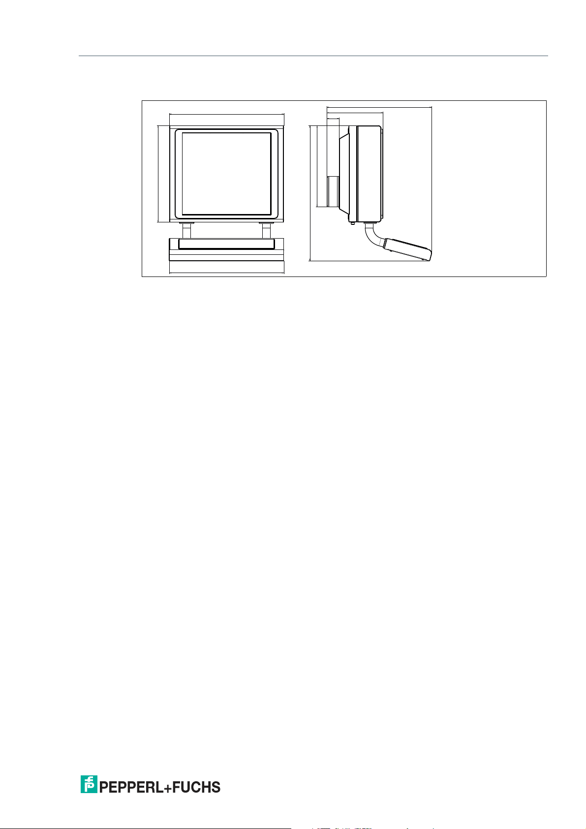
Flush Mount Installation
The 19-inch VisuNet GXP can also be flush mounted. With this mounting option (-NN), no
bezel is installed, and the monitor is recessed into the installation surface. This mounting must
be done from the back of the housing, and the fitting is kept inside the surface of the wall. The
cutout dimensions and stud location must match those on the GXP exactly.
Figure 3.12 VisuNet GXP flush mounted
Note
For more options and accessories, contact your local Pepperl+Fuchs sales representative.
54
2020-09
Page 55

VisuNet GXP
490
582
583
62
532
285
686
413
Mechanical Installation
3.6 Wall Mount Installation
Warning!
Proper installation
It is the installer's responsibility to select a suitable location with sufficient strength to hold the
equipment. It is the installer's responsibility to select the proper screws based on the installation conditions.
Required Components
• 19-inch VisuNet GXP prepared for wall mounting (front opening of the AG1 housing H2
option)
• Wall bracket adapter for wall mounting installation compatible with AG1 housing
• Optional EXTA2-J-F-****-U02CF-F-10-N keyboard/mouse (ordered separately)
Required Installation Tools
• 5 mm hex wrench for attaching the wall bracket screws to the AG-XX00-* housing
• Loctite® Threadlocker Blue 243®
• Cable gland installation tool
• Size 8 socket wrench for ground bolt
All tools should be torque controlled if a torque is specified.
2020-09
55
Page 56

VisuNet GXP
Mechanical Installation
Installation Steps
1.
Open the AG1 housing. See chapter 3.3.5
2.
Install cable glands with counter nuts and the two ground studs into the AG1 back wall where
indicated in the image below.
3.
Close the AG1 housing.
4.
Install the wall bracket to the AG1 housing with the included M8 screws and lock washers.
5.
Install the assembled unit to the wall with the appropriate mounting material.
Note
Secure the cable gland counter nut with a medium-strength bolt adhesive (e.g., Loctite®
Threadlocker Blue 243®).
56
2020-09
Page 57

VisuNet GXP
Appendix
4 Appendix
4.1 Accessories
Mounting and Installation
Item Number Type Code Description
Contact sales for model number selection
198768 WALL-BRACKET5 Direct wall mount bracket for
Peripherals
Item Number Type Code Description
Contact sales for individual
configuration
Contact sales for model selection
Contact sales for model selection
548333 CBL-IDMx60-D-J1-S-S18-N0 Cable for connecting IDMx-
548334 CBL-IDMx60-D-J1-S-C38-N0 Cable for connecting IDM-Z1-
548268 SCANNER-HOLDER-U1-
548395 HOLDER-BRACKET-AG1-
PEDESTAL5-XXXX-* StandardLine or BasicLine
EXTA2 product family Keyboard and mouse system
IDM-Z1-x60-D* Corded 1-D and 2-D handheld
IDM-Z1-x61-M* Bluetooth 1-D and 2-D hand-
AG1-N0
IDMx61-B-N0
pedestal
VisuNet GXP AG1 housing,
stainless steel (1.4301/304
Mounting options for Zone
1/21 hazardous locations
reader for Zone 1/21
held reader for Zone 1/21
Z1-60-D-* barcode readers to
the VisuNet GXP
Length: 1.8 m
x60-D-* barcode readers to
the VisuNet GXP
Length: 3.8 m
Scanner holder compatible
with AG1 housing
Material: stainless steel AISI
316L (1.4404)
Compatible with IDM-Z1-6x,
IDM-6x, ecom Ident-Ex 01,
and PSCAN
Prepared for mounting to right
side of housing
Bracket to mount IDM-Z1-61*, IDM-x61-* base station to
AG1 housing
Material: stainless steel AISI
304 (1.4301)
Assembly: right side of AG1
housing
Includes bracket and installation materials
Note: base station and cables
not included!
Note
For more options and accessories, contact your local Pepperl+Fuchs sales representative.
2020-09
57
Page 58

VisuNet GXP
This document contains safety-relevant information. It must not be altered without the authorization of a NE EX
Only valid as long as released in EDM
date: 2017-AUG-28
Control Drawing for GXP Sysytem and TCU or PCU No n-incendive Outputs
116-B034A
Global
sheet 1 of 1
Connections
X3.1 / X3.5 – VCC
X3.2 / X3.6 – DX3.3 / X3.7 – D+
X3.4 / X3.8 – GND
X4.1 / X5.1 - Us
X4.4 / X5.4 - TxD
X4.6 / X5.6 - RxD
X4.2 / X5.2 – GND
X4.4 / X5.4 - TxD
X4.6 / X5.6 - RxD
X4.2 / X5.2 - GND
NI Apparatus
NI Apparatus
NI Apparatus
GXP TCU or PCU NI Outputs
Hazardous Location
Class I, Division 2, Groups A, B, C, D; T4
Class II, Division 2, Groups F, G; T4
Class III
Class I Zone 2, Group IIC; T4
Class II Zone 22, Group IIIB; T85°C
Class III Zone 22, Group IIIA; T85°C
Hazardous Location
Class I, Division 2, Groups A, B, C, D; T4
Class II, Division 2, Groups F, G; T4
Class III
Class I Zone 2, Group IIC; T4
Class II Zone 22, Group IIIB; T85°C
Class III Zone 22, Group IIIA; T85°C
Type 1
Type 2
Type 3
Notes
1. The Entity Concept allows interconnection of non-incendive apparatus with associated apparatus not specifically
examined in combination as a system when the approved values of Voc (or Uo) and Isc (or Io) for the associated
apparatus are less than or equal to Vmax (Ui) and Imax(Ii) for the non-incendive apparatus and the approved values of
Ca(Co) and La(Lo) for the associated apparatus are greater than Ci + Ccable and Li + Lcable, respectively, for the nonincendive apparatus,
Where Ccable= 60pF/ft if unknown
Where Lcable= 0.20uH/ft if unknown
2. Simple apparatus: an electrical component or combination of components of simple construction with well-defined
electrical parameters that does not generate more than 1.5 V, 100mA, 25mW, or is a passive component that does not
disipate more than 1.3W and is compatible with the intrinsic safety of the circuit in which it is used.
3. Wiring methods must be in accordance with all applicable installation requirements of the county in use. For US, this is
NFPA 70 (NEC) article 504 with additional information in ANSI-ISA –RP12.06.01. For Canada this is CSA 22.1-12 (CEC)
section 18 and appendix F.
Entity Parameters
Parameter
Type 1
Type 2
Type 3
Maximum Output Voltage Uo (Voc)
4.92 V
8.95 V
8.95 V
Maximum Output Current Io (Isc)
182 mA
150 mA
58 mA
Maximum Output Power Po
570 mW
1.4 W
128 mW
Maximum external capacitance Co (Ca)
11.5 μF
19.5 μF
26.5 μF
36.5 μF
57.5 μF
400 nF
1.9 μF
Maximum external inductance Lo (La)
9 μH
4 μH
3 μH
2 μH
1 μH
199 μH
199 μH
Appendix
4.2 UL Control Drawing
58
2020-09
Page 59

Pepperl+Fuchs Qua lit y
Download our latest poli cy he re:
www.pepperl-fuchs.com/quali ty
© Pepperl+Fuchs · Subject to modifications
www.pepperl-fuchs.com
Printed in Germany / DOCT-5945D
 Loading...