

Page 1
VisuNet GMP RM/PC 200 series
Hardware manual
PROCESS AUTOMATION
MANUAL
Page 2

With regard to the supply of products, the current issue of the following document is ap-
plicable: The General Terms of Delivery for Products and Services of the Electrical Indus-
try, published by the Central Association of the Electrical Industry (Zentralverband
Elektrotechnik und Elektroindustrie (ZVEI) e.V.) in its most recent version as well as the
supplementary clause: "Expanded reservation of proprietorship"
VisuNet GMP RM/PC 200 series
Page 3

VisuNet GMP RM/PC 200 series
3
1 Safety ........................................................................................... 5
1.1 Validity................................................................................................... 5
1.2 Symbols Used ...................................................................................... 5
1.3 System Operator and Personnel ........................................................ 5
1.4 Pertinent Laws, Standards, Directives, and further Documentation6
1.5 Intended use......................................................................................... 6
1.6 Installation and commissioning ......................................................... 6
2 Product Specifications............................................................... 7
2.1 Overview ............................................................................................... 7
2.2 Technical Data VisuNet GMP RM/PC219............................................ 8
2.3 Technical Data VisuNet GMP RM/PC221.......................................... 10
2.4 Technical Data VisuNet GMP RM/PC222.......................................... 11
2.5 Dimensions VisuNet GMP PC/RM219 .............................................. 12
2.6 Dimensions VisuNet GMP PC/RM221 and PC/RM222 .................... 13
2.7 Image Sticking ................................................................................... 13
2.8 Interfaces and Connections.............................................................. 13
2.8.1 RS232/RS485.................................................................................. 14
2.8.2 USB 2.0 ........................................................................................... 14
2.8.3 Network RJ 45 ................................................................................. 14
2.8.4 Ground Connection.......................................................................... 14
2.8.5 Supply Voltage 24 V......................................................................... 15
2.8.6 Supply Voltage 120/230 V (AC)........................................................ 15
2.8.7 Connection Barcode handheld ........................................................ 15
Page 4

4
VisuNet GMP RM/PC 200 series
2.9 Accessories ........................................................................................ 16
2.9.1 Keyboards........................................................................................ 16
2.9.2 Pedestals ......................................................................................... 19
2.9.3 Wall arm versions............................................................................. 20
2.9.4 Wall bracket...................................................................................... 21
2.9.5 Hole pattern for mounting versions turnable/fix................................. 21
2.9.6 Hole pattern for the wall bracket ....................................................... 23
2.9.7 Power supply and network accessories............................................ 23
2.9.8 Barcode Reader ............................................................................... 24
2.9.9 Dimensions with Barcode handheld ................................................. 25
2.9.10 Holder for handheld barcode reader................................................. 26
3 Installation and Commissioning ............................................. 27
3.1 Preparation..........................................................................................27
3.2 Mounting in the field ..........................................................................27
3.2.1 Grounding at housing ....................................................................... 27
3.2.2 Grounding at Pedestal...................................................................... 28
3.3 General Mounting Information...........................................................30
3.4 Mounting the pedestal .......................................................................30
3.5 Mounting to wall arm.......................................................................... 34
3.6 Mounting to wall bracket ...................................................................38
3.7 Commissioning VisuNet GMP RM/PC ..............................................41
4 Appendix ................................................................................... 42
4.1 Chemical resistance of keyboard foil ...............................................42
4.2 Anti microbial resistance of keyboard foil .......................................42
4.3 Chemical resistances of the touch screen ...................................... 42
4.4 Chemical Resistance of the Display Foil Frame used in versions
with touch screen44
4.5 Change the keyboard TA3-K* ............................................................46
4.5.1 Dismount a keyboard TA3-K* ........................................................... 46
4.5.2 Attach the keyboard TA3-K* .............................................................47
Page 5
VisuNet GMP RM/PC 200 series
Safety
2018-07
5
1 Safety
1.1 Validity
The chapter “Safety” is valid as instruction manual.
Specific processes and instructions in this instruction manual require special provisions to
guarantee the safety of the operating personnel.
1.2 Symbols Used
This document contains symbols for the identification of warning messages and of informative
me
ssages.
Warning Messages
You will find warning messages, whenever dangers may arise from your actions. It is mandatory
that you observe these warning messages for your personal safety and in order to avoid
property damage.
Depending on the risk level, the warning messages are displayed in descending order as
follows:
Informative Symbols
Ac
tion
This symbol indicates a paragraph with instructions. You are prompted to perform an action or
a s
equence of actions.
1.3 System Operator and Personnel
Responsibility for planning, assembly, commissioning, operation, maintenance, and
dis
mounting lies with the plant operator.
The personnel must be appropriately trained and qualified in order to carry out mounting,
installation, commissioning, operation, maintenance, and dismounting of the device. The
trained and qualified personnel must have read and understood the instruction manual.
Danger!
This symbol indicates an imminent danger.
Non-observance will result in personal injury or death.
Warning!
This symbol indicates a possible fault or danger.
Non-observance may cause personal injury or serious property damage.
Caution!
This symbol indicates a possible fault.
Non-observance could interrupt the device and any connected systems and plants, or result in
their complete failure.
Note!
This symbol brings important information to your attention.
Page 6

2018-07
6
VisuNet GMP RM/PC 200 series
Safety
1.4 Pertinent Laws, Standards, Directives, and further Documentation
Observe laws, standards, and directives applicable to the intended use and the operating
location. Observe Directive 1999/92/EC in relation to hazardous areas.
The corresponding datasheets, manuals, declarations of conformity, EU-type examination
certificates, certificates, and control drawings if applicable (see datasheet) are an integral part
of this document. You can find this information under www.pepperl-fuchs.com.
Due to constant revisions, documentation is subject to permanent change. Please refer only to
the most up-to-date version, which can be found under www.pepperl-fuchs.com.
1.5 Intended use
The device is only approved for appropriate and intended use. Ignoring these instructions will
vo
id any warranty and absolve the manufacturer from any liability.
The devices must not be repaired, changed or manipulated. If there is a defect, the product
must always be replaced with an original device.
1.6 Installation and commissioning
The device must only be operated in the specified ambient temperature range and at the
sp
ecified relative humidity without condensation.
Use shielded cable
To connect interfaces only use shielded cable.
Screwing/locking connectors
To advance the cable shield screw/lock the connectors.
The device must be disconnected from the power supply prior to installation and maintenance.
The power supply may be activated only after all the circuits required for operation have been
fully assembled and connected.
Leading of data cables and power circuit lines
Lead data cable and power circuit line in separate cable channels.
Check cables and connectors
Before commissioning the system check all cables and connectors.
Page 7
VisuNet GMP RM/PC 200 series
Product Specifications
2018-07
7
2 Product Specifications
2.1 Overview
GMP (“Good Manufacturing Practice”) is a set of guidelines for assuring the quality of
production processes in controlled industries and closely follow the guidelines issued by the
European Commission or the FDA in the US. GMP applications are typically used in the
pharmaceutical and food industries. However, products that conform with GMP guidelines are
also required for the manufacture of cosmetics, flavour and nutrition.
The materials selected, design of the surfaces and architecture of the overall system should
prevent the accumulation of fluids and dirt. Cleaning, maintenance, inspection and servicing
must be as safe and easy as the processes employed for the disinfection of mechanical
components.
The VisuNet GMP product portfolio extends from simple direct monitors and remote monitor
systems with Ethernet connection to a host, to complete PCs available with single or dual
monitor systems and various mounting options. Both, models with 19", 21.5" (Full HD) and 22"
displays (with optional touch screen) are available. The stainless steel housings have an IP65
degree of protection. Remote monitors and PCs are equipped with Ethernet, USB and
RS232/RS485 interfaces.
Figure 2.1 Several models
The VisuNet GMP product family guarantees a perfect fit for every system infrastructure. Four
m
o
dels are available depending on the functions required, the display and input unit and the
distance over which the data is transferred. This manual describes the following two models:
Page 8
2018-07
8
VisuNet GMP RM/PC 200 series
Product Specifications
VisuNet GMP PC - Special Features
■ Available as 19'', 21.5" or 22'' monitor
■ Network based data transfer via Ethernet
■ Adapted for distances up to 100 m (or 2 km by using an optionbox)
VisuNet GMP RM - Special Features
■ Available as 19'', 21.5" or 22'' monitor
■ Can also be operated as Extended Desktop, Clone Display and with several host PCs
■ Network based data transfer via Ethernet (optional RDP, VNC or ICA)
■ Adapted for distances up to 100 m (or 2 km by using an optionbox)
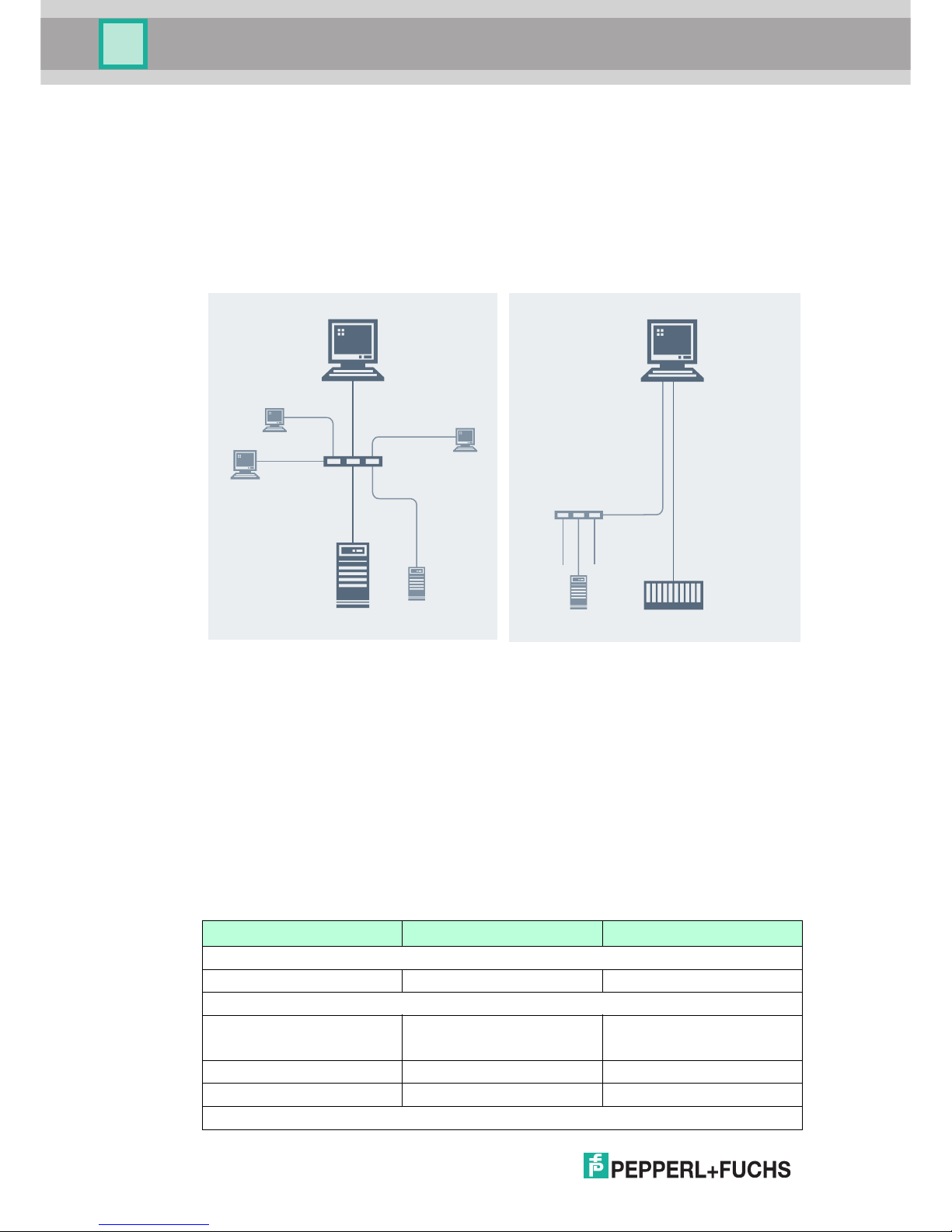
2.2 Technical Data VisuNet GMP RM/PC219
The remote monitor automatically connects to
the host using RDP, ICA or VNC, enabling via
the network.
The following drawing shows a typical system
topology:
The complete panel PC system has many
standard interfaces (network, USB, serial).
The operating system used is Windows 7
Ultimate (32-bit or 64-bit) or Windows 10 IoT
Enterprise LTSB (x 64). Customers can,
therefore, install software packages for
control, visualization and production. The
system operates independently of any
external computing power.
The following drawing shows a typical system
topology:
RM
ETHERNET
SWITCH
HOST
RM
HOST
RM
RM
PC
PLC
ETHERNET
HOST
VisuNet GMP RM219 VisuNet GMP PC219
General specifications
Type Remote Monitor Panel PC
Hardware
Processor
Thin Client - 1.46 GHz Intel
®
Atom™ E3826
Intel® Atom™ E3826 1.46 GHz
RAM Up to 8 GB RAM
Mass storage 120 GByte Solid State Drive
Supply
4 GB RAM
compact flash: 32 GB CFAST
Page 9
VisuNet GMP RM/PC 200 series
Product Specifications
2018-07
9
Rated voltage 24 V DC or 115 V AC / 230 V AC
Input voltage range 20 ... 30 V DC or 90 ... 240 V AC
Power consumption max. 60 W
Indicators/operating means
Display
Type TFT, LCD
Screen diagonal 48.3 cm (19 inch)
Resolution 1280 x 1024 Pixel
Color depth 16.7 Mio. (24 bit, true color)
Contrast 2000:1
Brightness
300 cd/m
2
Life span 50.000 h @ 25 °C
Input devices Analog resistive touchscreen (optional) ,
Keyboard with integrated mouse functionality: optical
trackball/touchpad/joystick versions available
Electrical specifications
Inrush current
max. 100 A @ 240 VAC approx. 0.5 ms
Interface
Interface type 2x RS 232
2x USB (Usage depends on
chosen remote protocol)
2x USB (for keyboard/mouse
connection)
2x Network RJ45
2x RS 232
2x USB
2x USB (for keyboard/mouse
connection)
2x Network RJ45
Software
Operating system
Windows 7 Embedded
Standard (RM Shell 4) or
Windows 7 Ultimate FES (32-
bit or 64-bit) or Windows 10
Compliance with standards and directives
Standard conformity
Electrical safety EN 60950-1 Class I equipment
Ambient conditions
Ambient temperature
0 ... 50 °C (32 ... 122 °F)
Altitude
2000 m above MSL (version AC)
Mechanical specifications
Degree of protection IP65
Material
Surface stainless steel 1.4301 / AISI 304
Surface quality Ra ≤ 0.8 µm
Mounting type slim line housing
several mounting types (pedestal, wall bracket, wall arm each turnable or fix) available
Mass approx. 12 kg
Dimensions 568 mm x 450 mm x 73 mm
VisuNet GMP RM219 VisuNet GMP PC219
Windows 10 IoT (RM Shell 5)
IoT Enterprise LTSB (x 64)
Page 10
2018-07
10
VisuNet GMP RM/PC 200 series
Product Specifications
2.3 Technical Data VisuNet GMP RM/PC221
VisuNet GMP RM221 VisuNet GMP PC221
General specifications
Type Remote Monitor Panel PC
Hardware
Processor
Thin Client - 1.46 GHz Intel
®
Atom™ E3826
Intel® Atom™ E3826 1.46 GHz
RAM Up to 8 GB RAM
Mass storage 120 GByte Solid State Drive
Supply
Rated voltage 24 V DC or 115 V AC / 230 V AC
Input voltage range 20 ... 30 V DC or 90 ... 240 V AC
Power consumption max. 60 W
Indicators/operating means
Display
Type TFT, LCD
Screen diagonal
54.6 cm (21.5 inch)
Resolution
1920 x 1080 pixel
Color depth 16.7 Mio. (24 bit, true color)
Contrast
5000:1
Brightness
300 cd/m
2
Life span 50.000 h @ 25 °C
Input devices Analog resistive touchscreen (optional) ,
Keyboard with integrated mouse functionality: optical
trackball/touchpad/joystick versions available
Electrical specifications
Inrush current max. 100 A @ 240 VAC approx. 0,5 ms
Interface
Interface type 2x RS 232
2x USB (Usage depends on
chosen remote protocol)
2x USB (for keyboard/mouse
connection)
2x Network RJ45
2x RS 232
2x USB
2x USB (for keyboard/mouse
connection)
2x Network RJ45
Software
Operating system
Compliance with standards and directives
Standard conformity
Electrical safety EN 60950-1 Class I equipment
Ambient conditions
Ambient temperature
0 ... 50 °C (32 ... 122 °F)
Altitude
2000 m above MSL (version AC)
Mechanical specifications
Degree of protection IP65
Windows 7 Embedded
Standard (RM Shell 4) or
Windows 7 Ultimate FES (32-
bit or 64-bit) or Windows 10
Windows 10 IoT (RM Shell 5)
IoT Enterprise LTSB (x 64)
4 GB RAM
compact flash: 32 GB CFAST
Page 11
VisuNet GMP RM/PC 200 series
Product Specifications
2018-07
11
2.4 Technical Data VisuNet GMP RM/PC222
Material
Surface stainless steel 1.4301 / AISI 304
Surface quality Ra ≤ 0.8 µm
Mounting type slim line housing
several mounting types (pedestal, wall bracket, wall arm each turnable or fix) available
Mass
approx. 13 kg
Dimensions
625 mm x 450 mm x 73 mm
VisuNet GMP RM221 VisuNet GMP PC221
VisuNet GMP RM222 VisuNet GMP PC222
General specifications
Type Remote Monitor Panel PC
Hardware
Processor
Thin Client - 1.46 GHz Intel
®
Atom™ E3826
Intel® Atom™ E3826 1.46 GHz
RAM Up to 8 GB RAM
Mass storage 120 GByte Solid State Drive
Supply
Rated voltage 24 V DC or 115 V AC / 230 V AC
Input voltage range 20 ... 30 V DC or 90 ... 240 V AC
Power consumption max. 60 W
Indicators/operating means
Display
Type TFT, LCD
Screen diagonal 55.9 cm (22 inch)
Resolution 1680 x 1050 pixel
Color depth 16.7 Mio. (24 bit, true color)
Contrast 1000:1
Brightness
300 cd/m
2
Life span 50.000 h @ 25 °C
Input devices Analog resistive touchscreen (optional) ,
Keyboard with integrated mouse functionality: optical
trackball/touchpad/joystick versions available
Electrical specifications
Inrush current max. 100 A @ 240 VAC approx. 0,5 ms
Interface
Interface type 2x RS 232
2x USB (Usage depends on
chosen remote protocol)
2x USB (for keyboard/mouse
connection)
2x Network RJ45
2x RS 232
2x USB
2x USB (for keyboard/mouse
connection)
2x Network RJ45
4 GB RAM
compact flash: 32 GB CFAST
Page 12
2018-07
12
VisuNet GMP RM/PC 200 series
Product Specifications
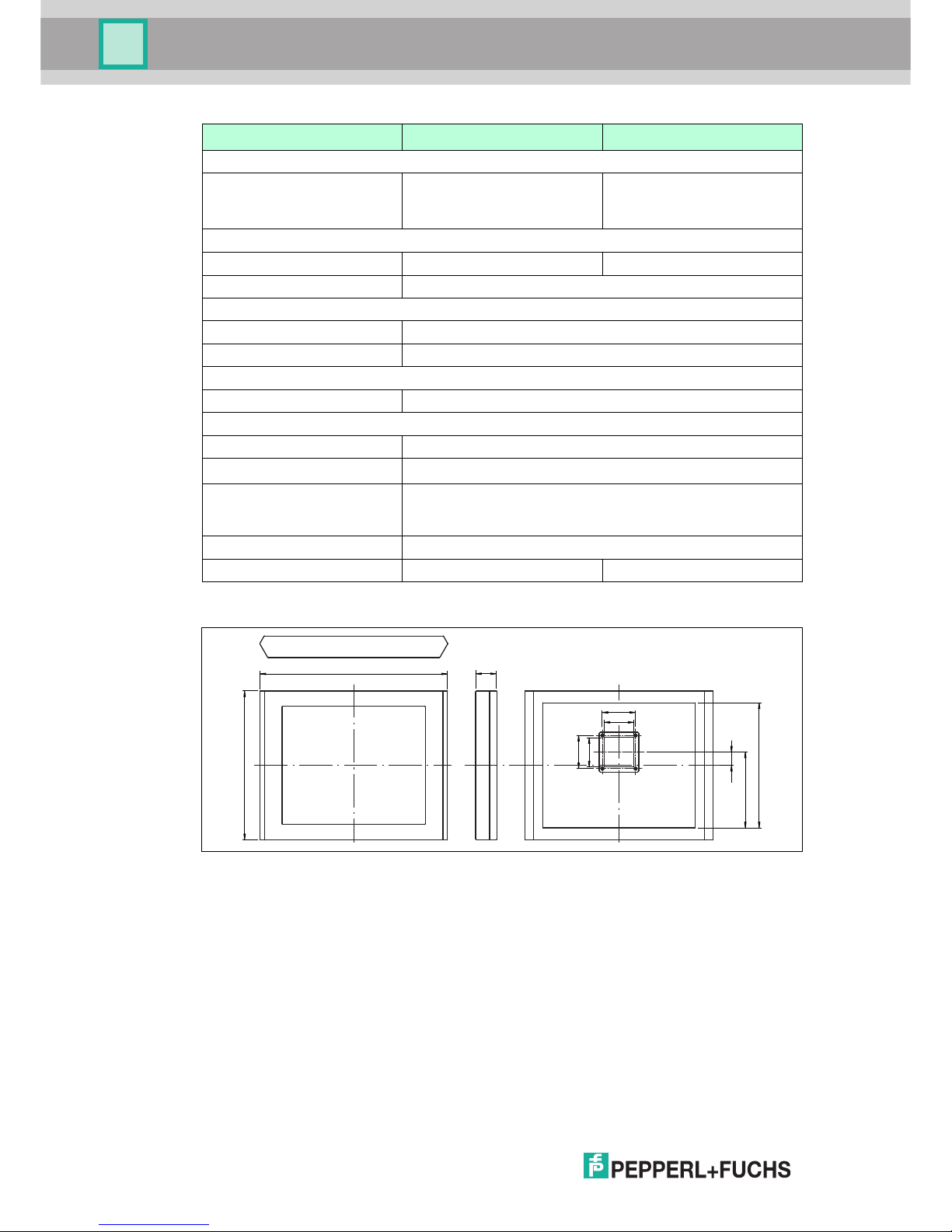
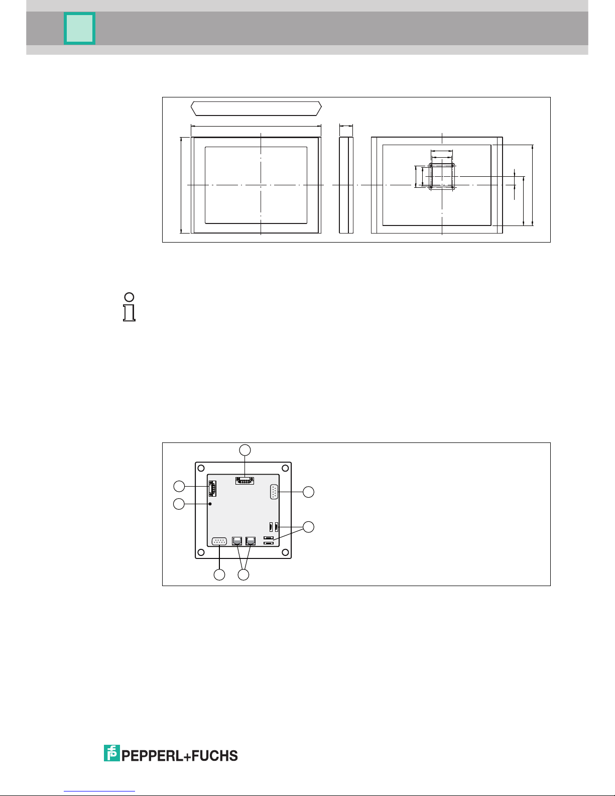
2.5 Dimensions VisuNet GMP PC/RM219
Figure 2.2 Dimensions VisuNet GMP PC/RM219
Software
Operating system
Compliance with standards and directives
Standard conformity
Electrical safety EN 60950-1 Class I equipment
Ambient conditions
Ambient temperature 0 ... 45 °C (32 ... 113 °F)
Altitude
2000 m above MSL (version AC)
Mechanical specifications
Degree of protection IP65
Material
Surface stainless steel 1.4301 / AISI 304
Surface quality Ra ≤ 0.8 µm
Mounting type slim line housing
several mounting types (pedestal, wall bracket, wall arm each turnable or fix) available
Mass approx. 13 kg
Dimensions 625 mm x 450 mm x 73 mm
VisuNet GMP RM222 VisuNet GMP PC222
9
10
9
10
228.5
378
39.5
568
450
73
Windows 7 Embedded
Standard (RM Shell 4) or
Windows 7 Ultimate FES (32-
bit or 64-bit) or Windows 10
Windows 10 IoT (RM Shell 5)
IoT Enterprise LTSB (x 64)
Page 13
VisuNet GMP RM/PC 200 series
Product Specifications
2018-07
13
2.6 Dimensions VisuNet GMP PC/RM221 and PC/RM222
Figure 2.3 Dimensions VisuNet GMP PC/RM221 and PC/RM222
2.7 Image Sticking
2.8 I
nterfaces and Connections
The interfaces and connections of the VisuNet GMP are located within the VESA adapter at the
ba
ck of the housing.
Figure 2.4 VESA adapter at the back of the VisuNet GMP housing
9
10
9
10
228.5
378
39.5
625
450
73
Note!
Image Sticking
Displaying a fixed pattern may cause burn-in-effects (image sticking due to the LCD
characteristics).
To avoid image sticking change pattern frequently or activate screen saver.
Please note that damages at the display caused to burn-in-effects are not included in the
warranty.
A Serial interface RS 232/RS485 (COM3)
B 4x USB (2x USB reserved fpr keyboard/mouse connection)
C 2x network RJ45
D Serial interface RS 232 RS 232 (COM1)
E Grounding bolt (M4)
F Power supply Phoenix DFK-MSTB 2,5/ 4-GF-5,08
G Connection Barcode handheld (COM6)
1
4
1
6
6
1
181
8
A
4
1
1
4
D
E
F
C
B
1
5
G
Page 14
2018-07
14
VisuNet GMP RM/PC 200 series
Product Specifications
2.8.1 RS232/RS485
9-pin D-sub plug required for serial device connection. Connection layout according to EIA-232
(RS232).
2.8.2 USB 2.0
4-pin USB socket (type A).
2.8.3 Network RJ 45
8-pin socket required for ethernet connection (10/100/1000 Base-TX).
Us
e Cat.5e cable (AWG24) or better for wiring.
2.8.4 Ground Connection
For connecting to a low resistance grounding point at the housing: see chapter 3.2.1
Fo
r connecting to a low resistance grounding point at pedestal/wall arm:
RS232 RS485
Picture Pin Signal Pin Signal
1 (Data) Carrier Detect 1 RS485 D-
2 Receive Data 2 n.c.
3 Transmit Data 3 RS485 D+
4 Data Terminal Ready 4 n.c.
5 GND 5 n.c.
6 Dataset Ready 6 n.c.
7 Request to Send 7 n.c.
8 Clear to Send 8 n.c.
9 Ring Indicator 9 GND
1
6 7 8 9
2 3 4 5
Picture Pin Signal Description
1 VCC USB power supply
2 USB- data
3 USB+ data
4 GND grounding
1 2 3 4
Picture Pin Signal
1 D1+ / TX+
2 D1- / TX-
3 D2+ / RX+
4 D3+
5 D3-
6 D2- / RX-
7 D4+
8 D4-
1 8
Page 15
VisuNet GMP RM/PC 200 series
Product Specifications
2018-07
15
2.8.5 Supply Voltage 24 V
4-pin socket required for supply voltage connection (Phoenix Contact DFK-MSTB 2,5/ 4-GF5,08).
The VisuNet GMP KM has inverse-polarity protection.
Matching plug: Phoenix Contact MSTBT 2,5/ 4-STF-5,08
2.8.6 Supply Voltage 120/230 V (AC)
4-pin socket required for supply voltage connection (Phoenix Contact DFK-MSTB 2,5/ 4-GF5,
08).
Matching plug: Phoenix Contact MSTBT 2,5/ 4-STF-5,08
2.8.7 Connection Barcode handheld
5-pin socket required for connecting Barcode handhelds (Phoenix Contact DFK-MSTB 2,5/ 5GF
-5,08).
Matching plug: Phoenix Contact MSTBT 2,5/ 5-STF-5,08
Picture Pin Signal
1 GND
2 GND
3 + 24 V DC
4 + 24 V DC
1
2
3
4
41
Danger!
Electric shock
Electric shock with heaviest personal injury to death. Heaviest property damage.
Connect the 4-pin socket as shown in the following table. Only connect the voltage suppy when
the device is completely installed.
Picture Pin Signal 120/230 V AC
1 PE
2 n. c.
3 L
4 N
1
2
3
4
41
Page 16

2018-07
16
VisuNet GMP RM/PC 200 series
Product Specifications
2.9 Accessories
The following accessories are available.
2.9.1 Keyboards
There are several keyboard models available. All keyboards have an antibacterial coating. For
th
is reason the keyboards are perfectly suitable for environments with high hygienic standards.
Keyboard TA3-K4
Keyboard with touchpad for controlling the mouse pointer.
2 separate buttons below the touchpad assume the function of left and right mouse button.
Figure 2.5 Keyboard with touchpad
Picture Pin Signal
1 12 V
2 GND
3 Rx
4 Tx
5 n.c.
5
4
3
2
1
51
TA3-K4
General specifications
Type Keyboard with touchpad
Supply
Rated voltage via data line
Indicators/operating means
Keyboard 105 short stroke keys
Keyboard layout: US international, German,
French, (further keyboard layouts on demand)
Page 17

VisuNet GMP RM/PC 200 series
Product Specifications
2018-07
17
Keyboard TA3-K6
Keyboard with joystick for controlling the mouse pointer.
2 s
eparate buttons below the joystick assume the function of left and right mouse button.
Figure 2.6 Keyboard with joystick
Touchpad
Active Principle capacitive
Resolution 40 Pts./mm
Dimensions 66 x 50 mm
Driver Microsoft Mouse ® , USB
Interface
Interface type USB
Conformity
Protection degree IP65
Ambient conditions
Ambient temperature -20 ... 55 °C (-4 ... 131 °F)
Storage temperature -20 ... 70 °C (-4 ... 158 °F)
Relative humidity max. 85 % , non-condensing
Mechanical specifications
Material anodized aluminium , Polyester foil
Mass 1.2 kg
Dimensions 482.6 mm x 177.8 mm x 45 mm
Cable length 1.8 m , wire end ferrule
TA3-K6
General specifications
Type Keyboard with joystick
Supply
Rated voltage via data line
TA3-K4
Page 18

2018-07
18
VisuNet GMP RM/PC 200 series
Product Specifications
Keyboard TA3-K8
Keyboard with optical trackball for controlling the mouse pointer.
2 s
eparate buttons below the trackball assume the function of left and right mouse button.
Figure 2.7 Keyboard with optical trackball
Indicators/operating means
Keyboard 105 short stroke keys
Keyboard layout: US international, German,
French, (further keyboard layouts on demand)
Joystick
Driver Microsoft Mouse ® , USB
Interface
Interface type USB
Conformity
Protection degree IP65
Ambient conditions
Ambient temperature -20 ... 55 °C (-4 ... 131 °F)
Storage temperature -20 ... 70 °C (-4 ... 158 °F)
Relative humidity max. 85 % , non-condensing
Mechanical specifications
Material anodized aluminium , Polyester foil
Mass 1.2 kg
Dimensions 482.6 mm x 177.8 mm x 45 mm
Cable length 1.8 m , wire end ferrule
TA3-K8
General specifications
Type Optical trackball
Supply
TA3-K6
Page 19

VisuNet GMP RM/PC 200 series
Product Specifications
2018-07
19
2.9.2 Pedestals
Figure 2.8 Pedestal models for VisuNet GMP
Rated voltage via data line
Indicators/operating means
Keyboard 105 short stroke keys
Keyboard layout: US international, German,
French, (further keyboard layouts on demand)
Trackball
Diameter 50 mm
Material [...] [...]
Driver Microsoft Mouse ® , USB
Interface
Interface type USB
Conformity
Protection degree IP65
Ambient conditions
Ambient temperature 0 ... 55 °C (32 ... 131 °F)
Storage temperature -10 ... 70 °C (14 ... 158 °F)
Relative humidity max. 85 % , non-condensing
Mechanical specifications
Material anodized aluminium , Polyester foil
Mass 1.2 kg
Dimensions 482.6 mm x 177.8 mm x 45 mm
Cable length 1.8 m , wire end ferrule
TA3-K8
A A AB B B
A
1500
500
1000
155
300
1270
1000
560
750
420
225
350
540
2 3 4 5 6 71
Page 20

2018-07
20
VisuNet GMP RM/PC 200 series
Product Specifications
2.9.3 Wall arm versions
Figure 2.9 Wall arms for VisuNet GMP
Model number Description
1 PEDESTAL1-150-1V-KP-G-T-304 Pedestal, turnable approx. 350°, inclination of
monitor 10°, with pipe for keyboard
2 PEDESTAL1-150-1V-KP-G-F-304 Pedestal, fix mounted, inclination of monitor 10°,
with pipe for keyboard
3 PEDESTAL1-150-1V-NP-G-T-304 Pedestal, turnable approx. 350°, inclination of
monitor 10°
4 PEDESTAL1-150-1V-NP-G-F-304 Pedestal, fix mounted, inclination of monitor 10°
5 PEDESTAL1-130-3V-NP-G-T-304 Pedestal, turnable approx. 350°, inclination of
monitor 30°
6 PEDESTAL1-130-3V-NP-G-F-304 Pedestal, fix mounted, inclination of monitor 30°
7 PEDESTAL1-56-3V-NP-G-T-304 Pedestal turnable approx. 350°, inclination of
monitor 30°
Model number Description
1 WALL-ARM1-55-1V-NT-G-*-304 Wall arm, inclination of monitor 10°, without pipe for
keyboard
2 models available:
■ WALL-ARM1-55-1V-NT-G-F-304: fix
■ WALL-ARM1-55-1V-NT-G-T-304: approx. 350°
turnable
2 WALL-ARM1-55-0V-KT-G-*-304 Wall arm, without inclination of monitor, with pipe for
keyboard
2 models available:
■ WALL-ARM1-55-0V-KT-G-F-304: fix
■ WALL-ARM1-55-0V-KT-G-T-304: approx. 350°
turnable
21
B B
500
775
575
100
250
815
520
865
990
285
Page 21

VisuNet GMP RM/PC 200 series
Product Specifications
2018-07
21
2.9.4 Wall bracket
Figure 2.10 Wall bracket for VisuNet GMP
2.9.5 Hole pattern for mounting versions turnable/fix
Angle of turn for turnable mounting version
The first stop plate is premounted for a max. angle of turn of 350°.
Wit
h the second enclosed stop plate you can define an individual angle.
The angle of turn can be devided with 6 screws in 60° steps.
Model number Description
1 WALL-BRACKET1-0-0V-G-
304
Wall bracket
1
C
Mounting version turnable, fastening at front:
129
9
40
A
Page 22

2018-07
22
VisuNet GMP RM/PC 200 series
Product Specifications
Figure 2.11 Turnable mounting version
1. Locking screw
2.
premounted stop plate
Mounting version fix:
2
1
42-50
90
9
63-64
B
Page 23

VisuNet GMP RM/PC 200 series
Product Specifications
2018-07
23
2.9.6 Hole pattern for the wall bracket
2.9.7 Power supply and network accessories
Power Supply
Ne
twork
Wall Bracket:
Ø 17
280
9
15
105
C
Model Number Description
BN-24/5000-HS-10 Power supply for safe area, DIN rail mounting
DATL-A2-4.0N/2.5F-2 Power cable 2x 4.0mm² +2.5m 2.5mm², wire end ferrule, length:
110 m
2DATL-A2-2.5-1 Power cable 2x 2.5mm², wire end ferrule, max. length 80 m
Model Number Description
SK-FX-100-1-8 Switch for safe area
DIN rail mounting, power supply 9-24 V DC, terminal connection,
1x fibre optics (SC-D), 8x Ethernet
DATL-C7TP-2-1RJ45 Cat.7 cable
RJZ2-SWITCH-5-10-AB RJ Switch, Power Supply 10-30V DC, IP67, 5x Ethernet
DATL-C7TP-1-1RJZ2 Cat.7 cable consistent with RJ Switch (2 pieces needed)
Page 24

2018-07
24
VisuNet GMP RM/PC 200 series
Product Specifications
2.9.8 Barcode Reader
The VisuNet GMP can operate an barcode handheld at its TTY interface. The following
products can be used at present:
Barcode handheld Powerscan PSCAN-D-1D-N0-R3-10-N
The PSCAN-D-1* consists of an barcode handheld with connecting cable. The connectiong
ca
ble is a 7 m long cable and a 8-pin M12 connector is mounted.
Order designation PSCAN-D-1*
Please also refer to the barcode reader operating instructions. For more information about the
terminal assignment see chapter 2.8.7.
Device Order designation Description
PSCAN-D-1* PSCAN-D-1D-N0-R3-10-N Barcode handheld
NON-Ex
Sparepart cable SPAREPARTS-PSCAN-D-GP-
CABLE-20
Sparepart cable for
PSCAN-D-1D-N0-R3-10-N
Page 25

VisuNet GMP RM/PC 200 series
Product Specifications
2018-07
25
2.9.9 Dimensions with Barcode handheld
Dimensions VisuNet GMP PC/RM 219 with Barcode handheld
Dimensions VisuNet GMP PC/RM221 and PC/RM222 with Barcode handheld
682
29,5
~187
~97
131
74
152
85
152
13
450
73
740
29,5
~187
~97
131
74
152
85
152
13
450
74
Page 26

2018-07
26
VisuNet GMP RM/PC 200 series
Product Specifications
2.9.10 Holder for handheld barcode reader
Dimensions
Figure 2.12 Abmessungen Halter für Barcode-Handheld
85
30
71,5
90
120
152
14
67,6
Page 27

VisuNet GMP RM/PC 200 series
Installation and Commissioning
2018-07
27
3 Installation and Commissioning
3.1 Preparation
Unpacking the unit
1. Check that all package contents are present and undamaged.
I
f anything is damaged, inform the shipper and contact the supplier.
2. Check that all items are present and correct based on your order and the shipping
documents.
If you have any questions, please contact Pepperl+Fuchs.
3. Keep the original packing material in case you need to store or ship the unit at a later time.
3.2 Mounting in the field
The device is licensed for operation in confined spaces.
The cooling of the device does not require active components like CPU fan or water cooling
systems. For that reason there are no ventilation slots in the housing.
To avoid overheating during operation, follow the advices below for field installation:
■ Do not expose the device to direct solar radiation or other heat sources.
■ Since the heat will dissipate via the housing, provide sufficient air circulation.
■ Keep the ambient temperature below the specified maximal value.
3.2.1 Grounding at housing
Figure 3.1 Ground connection at housing
Note!
The device is not delivered in sterile condition.
Note!
Pepperl+Fuchs recommand to use a cable with a core-cross section of 4 mm2 for grounding.
Page 28

2018-07
28
VisuNet GMP RM/PC 200 series
Installation and Commissioning
Grounding VisuNet GMP at housing
1. Insert the grounding cable into a cable lug (4).
2.
Unscrew the M4 screw nut on ground connection.
3. Insert the cable of the cable lug between the 2 washers (1).
4. Tighten the screw nut.
Figure 3.2 Equipotential bonding at the housing
3.2.2 Grounding at Pedestal
Note!
Depending on the grounding cable you need the adequate cable lug (not included in delivery).
1 washer
2 lock washer
3 screw nut
4 cable lug
1
2
3
4
Note!
Pepperl+Fuchs recommand to use a cable with a core-cross section of 4 mm2 for grounding.
Page 29

VisuNet GMP RM/PC 200 series
Installation and Commissioning
2018-07
29
Figure 3.3 Ground connection at pedestal
Grounding VisuNet GMP at pedestal and wall arm
1. Insert the grounding cable into a cable lug (4).
2.
Unscrew the M4 screw on ground connection.
3. Insert the cable of the cable lug between the 2 washers (1).
4. Tighten the screw.
Figure 3.4 Grounding at pedestal
Note!
Depending on the grounding cable you need the adequate cable lug (not included in delivery).
1 contact disk
2 screw nut
3 washer
4 lock washer
5 screw nut
6 hexagon socket set screw
7 cable lug
1
3 42
5
7
6
Page 30

2018-07
30
VisuNet GMP RM/PC 200 series
Installation and Commissioning
3.3 General Mounting Information
Tools required for assembly
Use the follwing tools for assembly (not included in the scope of supply):
■ Allen key, 3,5 mm, 3 mm, 4 mm
■ 4 stainless steel screws (M8) for wall/floor mount
■ Fork wrench for cable glands
Ch
oose the appropriated wrench size to tighten the cable glands:
Clamping Range in the Pedestal - Wrench Size
3.4 Mounting the pedestal
Mounting pedestal on the ground
1. To seal the pedestal against the floor, use the enclosed gasket.
2.
Mount the pedestal by using the 4 screws (M8).
Figure 3.5 Pedestal from bottom (photo) and from side (drawing)
1. Pedestal
2.
Gasket
3. Ground
Note!
Mounting with 2 persons
The following mounting requires 2 persons.
Note!
For fastening the pedestal, use 4 screws (M8) which suit the soil conditions.
Wrench Size Cable Diameter Torque
M16 20 4,5-10 mm 10 Nm
M20 24 7-13 mm 12 Nm
M25 29 9-17 mm 12 Nm
Note!
For fastening the pedestal, use 4 screws (M8) which suit the soil conditions.
1
2
3
Page 31

VisuNet GMP RM/PC 200 series
Installation and Commissioning
2018-07
31
Running the keyboard cable through the pedestal
If you use a pedestal with keyboard pipe (Pedestal1-150-1V-KP-G-T-304, Pedestal1-150-1V-
KP-G-F-304, Pedestal1-150-1K-KP-G-T-304, Pedestal1-150-1K-KP-G-F-304), a wire pull is
already installed for running the keyboard cable through the pedestal. Run the keyboard cable
first. Run all other connection cables after that.
1. Tighten the keyboard cable (2) to the wire pull (1).
2. Carefully pull the keyboard cable up through the pedestal.
3. Remove the wire pull from the keyboard cable.
4. Attach the keyboard with 2 grub screws on the pedestal.
Running cables through pedestal
For easier installation of the connection cables through the pedestal, wires are already installed
th
rough the pedestal and the cable glands (1).
1. Depending on cable diameter, choose the adequate cable gland (e.g. 1 cable gland for supply cable, 1 cable gland for network cable).
2. Attacht the connection cable to the current string and pull the cable carefully up.
3. Remove the strings from the connection cables.
1 Wire pull for keyboard cable
2 Keyboard cable
1
2
Page 32

2018-07
32
VisuNet GMP RM/PC 200 series
Installation and Commissioning
Connecting Cables to VisuNet GMP (Pedestal)
Connect all cables correctly.
Figure 3.6 Example of connection
1 Wire pull for connection cables
2 C
onnection cable
1
2
Page 33

VisuNet GMP RM/PC 200 series
Installation and Commissioning
2018-07
33
Mounting VisuNet GMP to Pedestal
1. Attach the VisuNet GMP with 4 countersunk screws with hexagon socket (M5x16). Use a
allen key (3 mm).
2. Tighten the screws (torque: 5-6 Nm)
Figure 3.7 Mounting VisuNet GMP to Pedestal
Tig
htening/Plugging up the pedestal/wall arm cable glands
1. Screw the cable glands with a fork wrench.
2.
To plug up cable glands that are not in use, lightly tighten the cable gland
3. Plug the plugs in.
4. Firmly thighten the cable gland.
Note!
The IP protection is ony ensured if either a cable is run or a plug is plugged in.
Note!
Pepperl+Fuchs recommand to use a cable with a core-cross section of 4 mm2 for grounding.
Page 34

2018-07
34
VisuNet GMP RM/PC 200 series
Installation and Commissioning
3.5 Mounting to wall arm
Fastening the wall arm
1. To secure the wall arm from wall unevenness, use the enclosed gasket.
2.
Mount the wall arm by using the 4 screws (M8).
Figure 3.8 Wall arm from side
1. Wall arm
2.
Wall
3. Gasket
Running the keyboard cable through the wall arm
If you use a wall arm with keyboard pipe (Wa
ll-Arm-1-55-1V-KT-G-F-304, Wall-Arm-1-55-1V-
KT-G-T-304), ia wire pull is already installed for running the keyboard cable through the wall
arm. Run the keyboard cable first. Run all other connection cables after that.
1. Tighten the keyboard cable (2) to the wire pull (1).
2. Carefully pull the keyboard cable up through the wall arm.
3. Remove the wire pull from the keyboard cable.
4. Attach the keyboard with 2 grub screws on the wall arm.
Caution!
Danger of instability
There are problems by keyboard entry. The device is not properly mounted to the wall.
Ensucre that the soil is stable. The soil must be able to absorb high mechanical energy. For
fastening the wall arm, use 4 screws (M8) which suit the soil conditions.
1
3
2
Page 35

VisuNet GMP RM/PC 200 series
Installation and Commissioning
2018-07
35
Running cables through wall arm
For easier installation of the connection cables through the wall arm, wires are already installed
th
rough the wall arm and the cable glands (1).
1. Depending on cable diameter, choose the adequate cable gland (e.g. 1 cable gland for supply cable, 1 cable gland for network cable).
2. Attacht the connection cable to the current string and pull the cable carefully up.
3. Remove the stings from the connection cables.
1 Wire pull for keyboard cable
2 Keyboard cable
3 VisuNet GMP
1
2
3
1 Wire pull for connection cable
2 Connection cable
3 VisuNet GMP
1
3
2
Page 36

2018-07
36
VisuNet GMP RM/PC 200 series
Installation and Commissioning
Mounting flexible Patch Cable (in Case of using turnable Wall Arm)
1. Connect the network plug of the inflexible patch cable via adapter (3) to the flexible patch cable
.
2. Connect the network plug of the flexible patch cable to the RJ45 interface of the monitor.
Figure 3.9 Mounting of flexible patch cable
Connecting Cables to VisuNet GMP (Wall Arm)
Connect all cables correctly.
Note!
In case of using a turnable wall arm apply flexible patch cable
Due to frequent monitor turning in live operation inflexible patch cable (1) is strained heavily
within the wall bracket (4). That may cause cable damage. Therefore, use flexible patch cable
(2).
1 Flexible patch cable
2 Adapter
3 inflexable network cable
1
3
2
Page 37

VisuNet GMP RM/PC 200 series
Installation and Commissioning
2018-07
37
Figure 3.10 Example of connection
Mounting VisuNet GMP to Wall Arm
1. Attach the VisuNet GMP with 4 countersunk screws with hexagon socket (M5x16). Use a
alle
n key (3 mm).
2. Tighten the screws (torque: 5-6 Nm)
Figure 3.11 Mounting VisuNet GMP to Wall Arm
Tig
htening/Plugging up the pedestal/wall arm cable glands
Note!
The IP protection is ony ensured if either a cable is run or a plug is plugged in.
Page 38

2018-07
38
VisuNet GMP RM/PC 200 series
Installation and Commissioning
1. Screw the cable glands with a fork wrench.
2. To plug up cable glands that are not in use, lightly tighten the cable gland
3. Plug the plugs in.
4. Firmly thighten the cable gland.
3.6 Mounting to wall bracket
Fixing the screws for wall bracket on the wall
1. Place the drill holes on the wall. Therefor use the drilling template C.
2.
Attach the 4 screws (M8).
Running cable through wall bracket/VESA plate
1. Depending on cable diameter, choose the adequate cable gland (e.g. 1 cable gland for supply
cable, 1 cable gland for network cable).
2. Feed the cable through the wall bracket as shown.
Note!
Pepperl+Fuchs recommand to use a cable with a core-cross section of 4 mm2 for grounding.
Note!
For fastening the wall bracket, use 4 screws (M8) which suit the soil conditions.
Ø 17
280
9
15
105
C
Page 39

VisuNet GMP RM/PC 200 series
Installation and Commissioning
2018-07
39
Connecting Cables to VisuNet GMP (Wall Bracket)
Connect all cables correctly.
Figure 3.12 Example of connection
Page 40

2018-07
40
VisuNet GMP RM/PC 200 series
Installation and Commissioning
Tightening/Plugging up the pedestal/wall arm cable glands
1. Screw the cable glands with a fork wrench.
2.
To plug up cable glands that are not in use, lightly tighten the cable gland
3. Plug the plugs in.
4. Firmly thighten the cable gland.
1. Grounding
Tightening the wall bracket and hooking the device
1. Tighten the 4 screws with washer and lock washer. Use the Allen Key SW4 (Torque: 5-6
Nm)
.
Note!
The IP protection is ony ensured if either a cable is run or a plug is plugged in.
Note!
Pepperl+Fuchs recommand to use a cable with a core-cross section of 4 mm2 for grounding.
1
Page 41

VisuNet GMP RM/PC 200 series
Installation and Commissioning
2018-07
41
2. Hook the device at the screes on the wall.
3.7 Commissioning VisuNet GMP RM/PC
Use a low restistance connection between device and control cabinet.
Us
e cables with a minimum cross core-section of 2,5 mm2 for power supply.
Turning on the VisuNet GMP
1. Connect the 4-pin plug with the 4-pin power supply socket at the back of the housing.
2.
Fix and tighten the screws of the plug.
3. Switch on the power supply at source.
After establishing the power supply the VisuNet GMP starts automatically. The green
LED on the right hand side of the housing indicates a correct power supply.
Turning off the VisuNet GMP
1. Disconnect the device from the power supply.
2.
After that unscrew the power plug at the VisuNet GMP.
Note!
Use the VisuNet GMP only with safety-low voltage (protective extra-low-voltage). The power
supply needs to be in line with applicable standards.
Page 42

2018-07
42
VisuNet GMP RM/PC 200 series
Appendix
4 Appendix
4.1 Chemical resistance of keyboard foil
The keyboard foil is manufactured from a biaxially aligned polyester-based material and
therefore has a greater restistance to solvents. The foil is stronger and more durable than other
standard foils used on keyboards and front panels, such as polycarbonate and PVC.
The keyboard foil is resistant against the following substances: (Test method: DIN42115):
■ Alcohols
■ Dilute acids
■ Dilute alkalis
■ Esters
■ Hydrocarbons
■ Household cleaning
4.2 Anti microbial resistance of keyboard foil
The foil passed the anti microbial effectiveness tested with (Test method: AATCC Test Method
10
0):
■ Staphyloccus aureus (MRSA)
■ Escherichia coli 0157
■ Listeria monocytogenes
■ Pseudomonas aeruginosa
■ Salmonella enteritidis
■ Bacillus cereus
■ Streptococcus faecalis
■ Klebsiella pneumoniae
■ Aspergillus niger
■ Penicillium purpurogenum
■ Phoma violacea
■ Saccharmyyces cerevisiae
4.3 Chemical resistances of the touch screen
The foil is manufactured from a biaxially aligned polyester-based material and therefore has a
gr
eater restistance to solvents. It is physically resistant to pencil lead with a maximum hardness
of 3HB.
The foil is resistant against the following substances (concenration 100 % - unless otherwise
specified):
Aldehyde:
Acetataldehyde Formaldehyde 37 - 42 %
Alcohols:
Ethanol Hexahydrophenol
Triacetin Dowandol DRM/PM
Glycol Glycerin
Isopropanol Methanol
Diacetone alcohol
Page 43

VisuNet GMP RM/PC 200 series
Appendix
2018-07
43
Hydrocarbons:
Aliphatic hydrocarbons generally gasoline
Kerosene Toluol
Xylene Benzene
Chlorinated hydrocarbons:
Chlorofluorocarbons Perchloroethylene
III-Trichloroethylene Diethyl ether
Methyl ethyl ketone Trichloroethylene
Acids:
Formic acid <10 % acetic acid <10 %
Phosphoric acid <10 % Hydrochloric acid <10 %
Nitric acid <10 % Trichloroacetic acid <10 %
sulfuric acid <10 %
Other organic solvents:
Ether Acetone
Dimethylformamide Dioxane
Ethyldioctyl Dibutyl phthalate
Phthalate Butyl cellosolve
Iron chlorid (FeCl2) Iron chlorid (FeCl3)
Lyes:
Ammonia <10 % Sodium hydroxide <10 %
Alkali carbonate
Ester:
Ethylacetate N-butyl acetate
Amyl acetate
Technical oils and greases:
Drilling emulsion Diesel oil
Varnish Heating oil
Liquid paraffin Castor oil
Silicone oil Turpentine oil substitute
Brake fluid Decon
Saline solutions:
Alkali carbonate Bichromate
Potassium hydroxide <30 % Acetonitrile
sodium bisulfate potassium ferrocyanide
Sodium hypochlorite <20 %
Various other substances:
Molecular chlorine Cresol phenol soaps in hydrogen soution
Oxygen Tricresyl phosphate
Water <100 °C Hydrogen peroxid <25%
Saline water Solvent (white spirit)
Aldehyde:
Page 44

2018-07
44
VisuNet GMP RM/PC 200 series
Appendix
Resistance to surface desinfectant can be determined on request.
Slight discoloration
Intense examinations established that the following products caused slight discoloration:
■ Mustard
■ Tomato juice
■ Tomato ketchup
■ Lemon juice
No resistance
Not resistant to:
■ c
oncentrated mineral acids
■ concentrated alkaline solutions
■ High-pressure steam over 100 °C
4.4 Chemical Resistance of the Display Foil Frame used in versions with
to
uch screen
The foil is manufactured from a biaxially aligned polyester-based material and therefore has a
gr
eater restistance to solvents.
The foil is resistant against the following substances (concenration 100 % - unless otherwise
specified):
Grape juice Milk
Coffee
Detergent, rising agent, cleaning agent:
Potash soap Detergent solutions (surfactants)
Fabric softener Sodium carbonate
Household chemicals (24 hours of exposure at 50 °C)
Top Job Jet Dry
Gumption Fantastic
Formula 409 Ariel
Persil Wisk
Lenor Downey
Ajax Vim
Domestos Vortex
Windex0
Aldehyde:
Note!
Various other substances may cause the surface structure to alter. Testing and subsequent
assessment still require clarification.
Ethanol Acetaldehyde 1.1.1. Trichloroethane
(Genklene)
Cyclohexanol Aliphatic hydrocarbons Amylacetate
Dowanol DRM/PM Diacetone Formaldehyde (37-42%) Butylcellosolve
Page 45

VisuNet GMP RM/PC 200 series
Appendix
2018-07
45
Resistance to surface desinfectant can be determined on request.
No resistance
Not resistant to:
■ B
enzyol alcohol
■ Concentrated caustic solution
■ Concentrated mineral acids
■ Dichloromethane
■ Dimethylformamide
■ High pressure steam at over 100°C
■ Methylene chloride
Glycerine Toluene Diethyl ether
Isopropanol Xylene Ether
Methanol White spirit Ethlacetate
Triacetin N-Butyl acetate
Acteone Acetic acid (<50%) Dibutyl Phthalate
Isophorone Formic acid (<50%) Dioctyl Phthalate
Cyclohexanone Hydrochloric acid (<36%) Fabric conditioner
Methylethylketone Nitric acid (<10%) Ferric Chloride (saturated)
Methylisobutileketone Sulphuric acid (<30%) Ferrous Chloride (saturated)
Lixtop Phosphoric acid (<30%) Hydrogen peroxide (<25%)
Trichloracetic acid (<50%) Potassium carbonate
Glutaraldehyde in water 50% Sodium carbonate (saturated)
Oleic Acid Sodium hypochlorite (<20%)
Tego51
Washing powders
Acetronitrile Blown castor oil Saturated Salt Solution
Ammonia (<32%) Cutting oil (hysol X) Water
Ammonium chloride (<10%) Decon
Sodium hydroxide (50%) Diesel oil
Dichromate Hydraulic oil (Castrol Anvol)
Potassium hydroxide (<40%) Linseed oil
Sodium bisulphate (<50%) Paraffin oil
Potassium
ferrocyanide/ferricyanide
Universal brake fluid (Castor
Girling)
Silver Nitrate Silicone oil
Teepol
Turpentine substitute
Petrol
Diabasic Ester 5
Skydrol 500B4
Page 46

2018-07
46
VisuNet GMP RM/PC 200 series
Appendix
■ Tetrahydrofuran
Slight discoloration
Intense examinations established that the following products caused slight discoloration:
■ Mustard
■ Tomato juice
■ Tomato ketchup
■ Lemon juice
■ Tea
■ Coffee
4.5 Change the keyboard TA3-K*
Assemly, commissioning, operation, maintenance and dismounting of any device may only be
ca
rried out by trained, qualified personnel.
4.5.1 Dismount a keyboard TA3-K*
Dismount a keyboard
1. Separate the silicon joint between housing and keyboard. Use a sharp edged tool for examle
a k
nife or a scalpel.
2. Open the bottom plate.
3. Remove the cable from the board: Pull the cables (1). Declamp the PE connector (2)
Declamp the cable clamp (3).
4. Remove the mounting rail of the keyboard. Remove the lock nuts. Remove the rails.
Note!
Various other substances may cause the surface structure to alter. Testing and subsequent
assessment still require clarification.
Caution!
Fault / Fail completely
Devices or any connected facilities or systems may develop a fault or fail completely.
Consider the ESD safety measures.
1
2
3
Page 47

VisuNet GMP RM/PC 200 series
Appendix
2018-07
47
5. Remove the keyboard and put it out of the front housing.
4.5.2 Attach the keyboard TA3-K*
Attach the keyboard
1. Remove the cover plate of the keyboard.
2.
Replace the 8x distance bolts to 8x lock nuts. Tighten the lock nuts, torque 0,3 Nm.
3. Remove the connecting cabel of the keyboard. See chapter see chapter 4.5.1.
4. Place the keyboard from the front into the housing.See chapter see chapter 4.5.1 in
reversed order.
5. Put the connection rails from the back to the keyboard and mount it with the new enclosed
lock nuts. Tighten the lock nut of each rail as compact the keyboard can be moved. Adjust
the keyboard central. Tighten all lock nuts with suited tools, torque 0,4 Nm..
6. Attach the cable clamp. Depending on the version of the keyboard there are one or two
cables.
7. Attach the PE cable. Depending on the version of the keyboard there are one or two cables.
Page 48

2018-07
48
VisuNet GMP RM/PC 200 series
Appendix
8. Put the cable into the board.
9.
Close the bottom plate.
10.To assure the GMP capability join the joint at the keyboard with silicon professionally.
1 Lock washer M3
2 Washer M3
3 Washer M4
4 Toothed lock washer M4
1
2
3
4
Page 49

VisuNet GMP RM/PC 200 series
Appendix
2018-07
49
This page left blank intentionally.
Page 50

Subj
ect to modifications
Copyright PEPPERL+FUCHS • Printed in Germany
www.pepperl-fuchs.com
Worldwide Headquarters
Pepperl+Fuchs GmbH
68307 Mannheim · Germany
Tel. +49 621 776-0
E-mail: info@de.pepperl-fuchs.com
For the Pepperl+Fuchs representative
closest to you check www.pepperl-fuchs.com/contact
PROCESS AUTOMATION –
PRO
T
ECTING YOUR PROCESS
DOCT-1798J
07/2018
 Loading...