

Pepperl Fuchs OMT550-R201-2EP-IO Data Sheet
Distance sensor
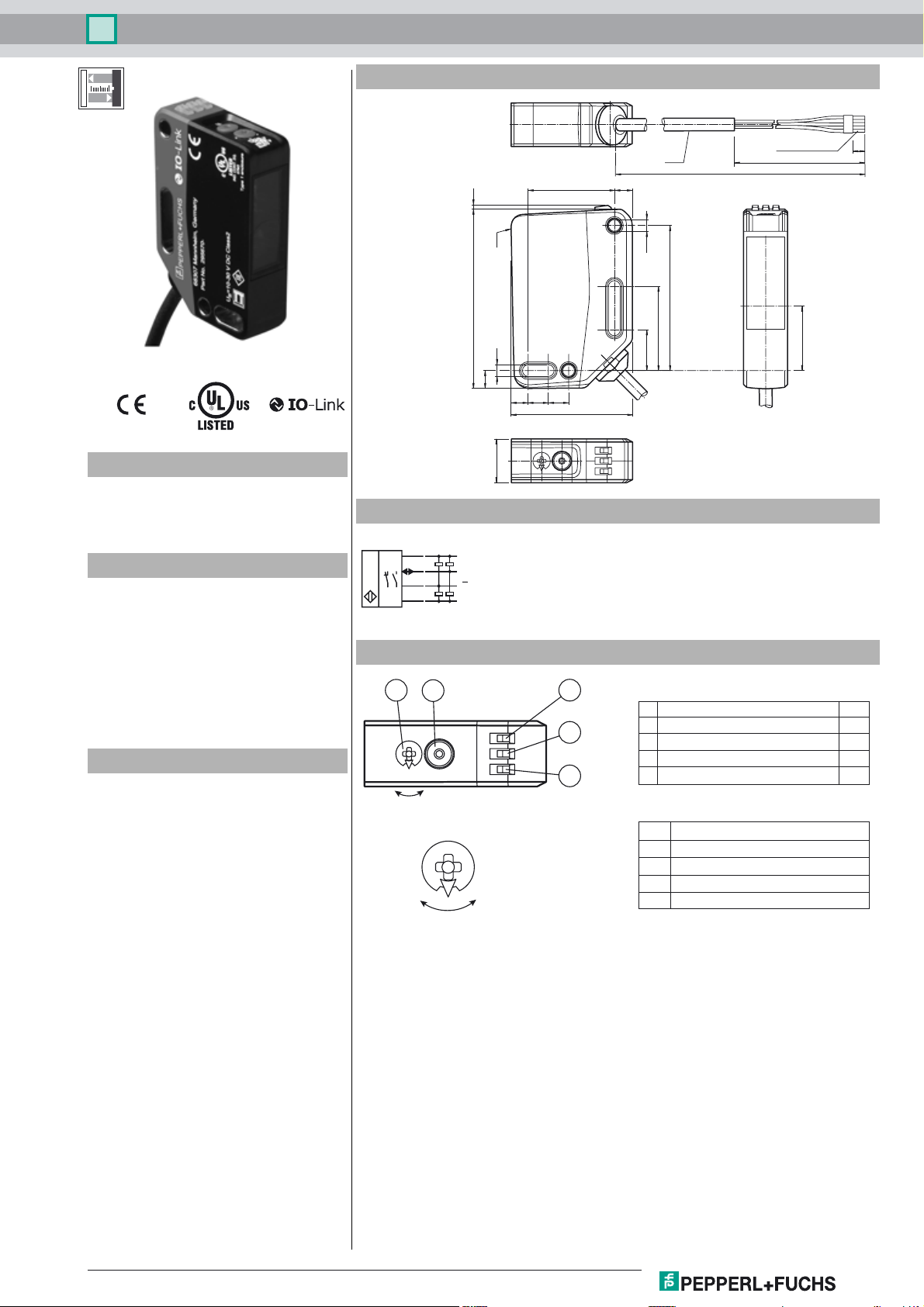
Dimensions
1.461.7
OMT550-R201-2EP-IO
Cable/clamping
ø 4.3
629.9
sleeve
L
L1
4
Model Number
OMT550-R201-2EP-IO
Distance sensor
with fixed cable
Features
• Medium design with versatile
mounting options
• Space-saving distance sensors in
small standardized design
• Multi Pixel Technology (MPT) - exact
and precise signal evaluation
• IO-link interface for service and
process data
Product information
The optical sensors in the series are the first
devices to offer an end-to-end solution in a
medium-sized standard design—from the
thru-beam sensor through to the measuring
distance sensor. As a result of this design,
the sensors are able to perform practically all
standard automation tasks.
The entire series enables sensors to
communicate via IO-Link.
The DuraBeam laser sensors are durable and
can be used in the same way as a standard
sensor.
Multi Pixel Technology (MPT) ensures that
the standard sensors are flexible and
can be adapted to the application
environment.
Ref.
4.2
6.2
5.8 7 7
15
Electrical connection
BN
L+
BK
C/Q
WH
BU
Q
L-
Indicators/operating means
1
2
0
B
Q2
A
B
Q1
A
41.7
ø 4.2
50
29
14
3
1 Mode rotary switch
4
5
2 Teach-in button
3 Switching output display Q2
4 Switching output display Q1
5 Operating indicator
Q1B Switching output 1/switch point B
Q1A Switching output 1/switch point A
Q2A Switching output 2/switch point A
Q2B Switching output 2/switch point B
0 Keylock
22.1
YE
YE
GN
Release date: 2018-07-27 10:11 Date of issue: 2019-10-31 295670-100176_eng.xml
Refer to "General Notes Relating to Pepperl+Fuchs Product Information".
Pepperl+Fuchs Group
1

Distance sensor
OMT550-R201-2EP-IO
Technical data
General specifications
Measurement range 100 ... 550 mm
Reference target standard white, 100 mm x 100 mm
Light source LED
Light type modulated visible red light
LED risk group labelling exempt group
Angle deviation max. +/- 1.5 °
Diameter of the light spot approx. 20 mm at a distance of 550 mm
Angle of divergence 2.5 °
Ambient light limit EN 60947-5-2 : 45000 Lux
Resolution 0.1 mm
Functional safety related parameters
MTTFd 600 a
Mission Time (TM) 20 a
Diagnostic Coverage (DC) 0 %
Indicators/operating means
Operation indicator LED green:
Function indicator LED yellow:
Control elements Teach-In key
Control elements 5-step rotary switch for operating modes selection
Electrical specifications
Operating voltage UB10 ... 30 V DC
Ripple max. 10 %
No-load supply current I
Protection class III
Interface
Interface type IO-Link ( via C/Q = pin 4 )
Device profile Identification and diagnosis
Transfer rate COM 2 (38.4 kBaud)
IO-Link Revision 1.1
Min. cycle time 3 ms
Process data witdh Process data input 4 byte
SIO mode support yes
Device ID 0x111911 (1120529)
Compatible master port type A
Output
Switching type The default setting is:
Signal output 2 push-pull (4 in 1)outputs, short-circuit protected, reverse
Switching voltage max. 30 V DC
Switching current max. 100 mA , resistive load
Usage category DC-12 and DC-13
Voltage drop Ud≤ 1.5 V DC
Response time 2 ms , see table 1
Conformity
Communication interface IEC 61131-9
Product standard EN 60947-5-2
Measurement accuracy
Temperature drift 0.05 %/K
Warm up time 5 min
Repeat accuracy ≤ 1 % , see table 1
constantly on - power on
flashing (4Hz) - short circuit
flashing with short break (1 Hz) - IO-Link mode
constantly on - switch output active
constantly off - switch output inactive
< 25 mA at 24 V supply voltage
0
Smart Sensor type 0/type 3.3
Process data output 2 bits
C/Q - BK: NPN normally open, PNP normally closed, IO-Link
Q2 - WH: NPN normally open, PNP normally closed
polarity protected, overvoltage protected
Accessories
IO-Link-Master02-USB
IO-Link master, supply via USB port or
separate power supply, LED indicators,
M12 plug for sensor connection
OMH-RL31-02
Mounting bracket narrow
OMH-RL31-03
Mounting bracket narrow
OMH-RL31-04
Mounting aid for round steel ø 12 mm or
sheet 1.5 mm ... 3 mm
OMH-RL31-07
Mounting bracket including adjustment
OMH-R20x-Quick-Mount
Quick mounting accessory
Other suitable accessories can be found at
Linearity error 0.75 %
Ambient conditions
Ambient temperature 10 ... 60 °C (50 ... 140 °F)
Storage temperature -40 ... 70 °C (-40 ... 158 °F)
Mechanical specifications
Housing width 15 mm
Housing height 61.7 mm
Housing depth 41.7 mm
Degree of protection IP67 / IP69 / IP69K
Connection 2 m fixed cable
Material
Housing PC (Polycarbonate)
Optical face PMMA
Mass approx. 73 g
Refer to "General Notes Relating to Pepperl+Fuchs Product Information".
Pepperl+Fuchs Group
2
Release date: 2018-07-27 10:11 Date of issue: 2019-10-31 295670-100176_eng.xml
 Loading...