

Page 1
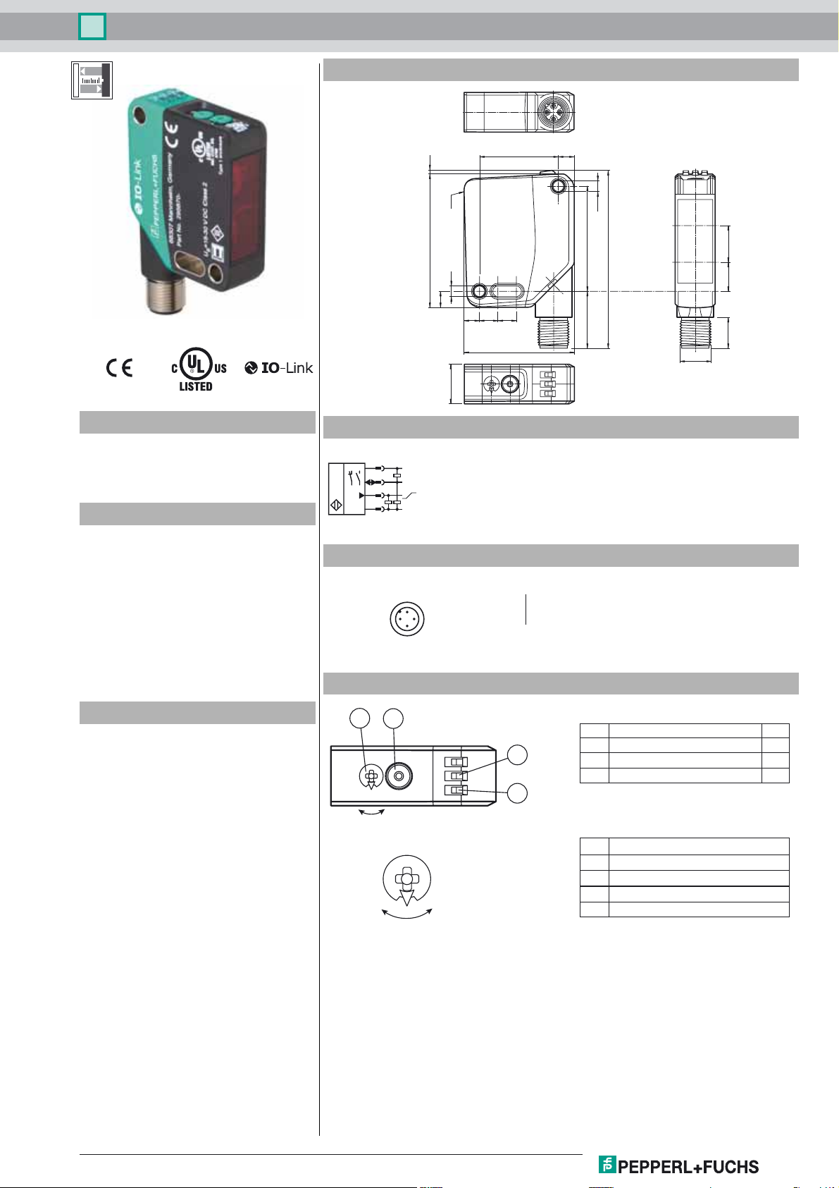
Distance sensor
OMT550-R200-IEP-IO-V1
Dimensions
Model Number
OMT550-R200-IEP-IO-V1
Distance sensor
with 4-pin, M12 x 1 connector
Features
• Medium design with versatile
mounting options
• Space-saving distance sensors in
small standardized design
• Multi Pixel Technology (MPT) - exact
and precise signal evaluation
• IO-link interface for service and
process data
• Analog output 4 ... 20 mA
1.450.6
Ref.
4.2
6.2
5.8 7 7
15
Electrical connection
1
L+
4
C/Q
2
I
3
L-
Pinout
1
2
4
3
Wire colors in accordance with EN 60947-5-2
1 BN
2 WH
3 BU
4 BK
Indicators/operating means
41.7
629.9
(brown)
(white)
(blue)
(black)
39.9
21.6
ø 4.2
67.4
Receiver
1411
Emitter
11.7
M12 x 1
Product information
The optical sensors in the series are the first
devices to offer an end-to-end solution in a
medium-sized standard design—from the
thru-beam sensor through to the measuring
distance sensor. As a result of this design,
the sensors are able to perform practically all
standard automation tasks.
The entire series enables sensors to
communicate via IO-Link.
The DuraBeam laser sensors are durable and
can be used in the same way as a standard
sensor.
Multi Pixel Technology (MPT) ensures that
the standard sensors are flexible and
can be adapted to the application
environment.
1
Q2
2
1 Mode rotary switch
3
2 Teach-in button
3 Switching output display Q1
4 Operating indicator
YE
GN
4
0
B
A
B
Q1
A
Q1B Switching output/switch point B
Q1A Switching output/switch point A
Q2A Analog output/value A
Q2B Analog output/value B
0 Keylock
Release date: 2019-02-11 10:57 Date of issue: 2019-10-31 295670-100253_eng.xml
Refer to "General Notes Relating to Pepperl+Fuchs Product Information".
USA: +1 330 486 0001 Singapore: +65 6779 9091
Germany: +49 621 776 1111Pepperl+Fuchs Group
1
Page 2
Distance sensor
OMT550-R200-IEP-IO-V1
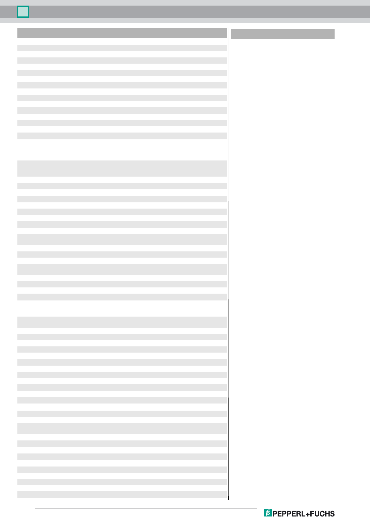
Technical data
General specifications
Measurement range 100 ... 550 mm
Reference target standard white, 100 mm x 100 mm
Light source LED
Light type modulated visible red light
LED risk group labelling exempt group
Angle deviation max. +/- 1.5 °
Diameter of the light spot approx. 20 mm at a distance of 550 mm
Angle of divergence 2.5 °
Ambient light limit EN 60947-5-2 : 45000 Lux
Resolution 0.1 mm
Functional safety related parameters
MTTFd 520 a
Mission Time (TM) 20 a
Diagnostic Coverage (DC) 0 %
Indicators/operating means
Operation indicator LED green:
Function indicator LED yellow:
Control elements Teach-In key
Control elements 5-step rotary switch for operating modes selection
Electrical specifications
Operating voltage UB18 ... 30 V DC
Ripple max. 10 %
No-load supply current I
Protection class III
Interface
Interface type IO-Link ( via C/Q = pin 4 )
Device profile Identification and diagnosis
Transfer rate COM 2 (38.4 kBaud)
IO-Link Revision 1.1
Min. cycle time 3 ms
Process data witdh Process data input 4 byte
SIO mode support yes
Device ID 0x111902 (1120514)
Compatible master port type A
Output
Switching type The default setting is:
Signal output 1 push-pull output , 1 analog output , short-circuit-proof, reverse
Switching voltage max. 30 V DC
Switching current max. 100 mA , resistive load
Usage category DC-12 and DC-13
Voltage drop Ud≤ 1.5 V DC
Response time 2 ms , see table 1
Analog output
Output type 1 current output: 4 ... 20 mA
Load resistor > 1 kΩ voltage output ; ≤ 470 Ω current output
Recovery time 2 ms
Conformity
Communication interface IEC 61131-9
Product standard EN 60947-5-2
Measurement accuracy
Temperature drift 0.05 %/K
Warm up time 5 min
Repeat accuracy ≤ 1 % , see table 1
constantly on - power on
flashing (4Hz) - short circuit
flashing with short break (1 Hz) - IO-Link mode
constantly on - switch output active
constantly off - switch output inactive
< 25 mA at 24 V supply voltage
0
Smart Sensor type 0/type 3.3
Process data output 2 bits
C/Q - Pin4: NPN normally open, PNP normally closed, IO-Link
I—Pin2: analog output 4...20 mA
polarity protection, surge-proof
Accessories
V1-G-2M-PUR
Female cordset, M12, 4-pin, PUR cable
V1-W-2M-PUR
Female cordset, M12, 4-pin, PUR cable
IO-Link-Master02-USB
IO-Link master, supply via USB port or
separate power supply, LED indicators,
M12 plug for sensor connection
OMH-MLV12-HWK
Mounting bracket for series MLV12
sensors
OMH-R200-01
Mounting aid for round steel ø 12 mm or
sheet 1.5 mm ... 3 mm
OMH-R20x-Quick-Mount
Quick mounting accessory
OMH-MLV12-HWG
Mounting bracket for series MLV12
sensors
Other suitable accessories can be found at
www.pepperl-fuchs.com
Linearity error 0.75 %
Ambient conditions
Ambient temperature 10 ... 50 °C (50 ... 122 °F)
Storage temperature -40 ... 70 °C (-40 ... 158 °F)
Mechanical specifications
Housing width 15 mm
Housing height 50.6 mm
Housing depth 41.7 mm
Degree of protection IP67 / IP69 / IP69K
Connection 4-pin, M12 x 1 connector, 90° rotatable
Refer to "General Notes Relating to Pepperl+Fuchs Product Information".
2
USA: +1 330 486 0001 Singapore: +65 6779 9091
Germany: +49 621 776 1111Pepperl+Fuchs Group
Release date: 2019-02-11 10:57 Date of issue: 2019-10-31 295670-100253_eng.xml
Page 3
Distance sensor
Material
Housing PC (Polycarbonate)
Optical face PMMA
Mass approx. 37 g
Approvals and certificates
UL approval E87056 , cULus Listed , class 2 power supply , type rating 1
CCC approval CCC approval / marking not required for products rated ≤36 V
OMT550-R200-IEP-IO-V1
Table 1: Information on Measured Value Filters
Measured value filter
Filter 1-way 2-way 4-way 16-way 64-way 256-way
Response time (ms) 2 4 8 32 128 512
Repeatability (%) < 1 %
Settings
Teach-In (TI)
Use the rotary switch for switching signal Q1 to select the relevant switching threshold A and/or B to teach in.
• The yellow LEDs indicate the current state of the selected output.
To teach in a switching threshold, press and hold the "TI" button for approximately 1 s, until the yellow and green LEDs flash in phase. Teach-in
starts when the "TI" button is released.
• Teach-in successful: the yellow and green LEDs flash alternately at 2.5 Hz.
• Teach-in unsuccessful: the yellow and green LEDs quickly flash alternately at 8 Hz.
After an unsuccessful Teach-in, the sensor continues to operate with the previous valid setting after the relevant visual fault signal is issued.
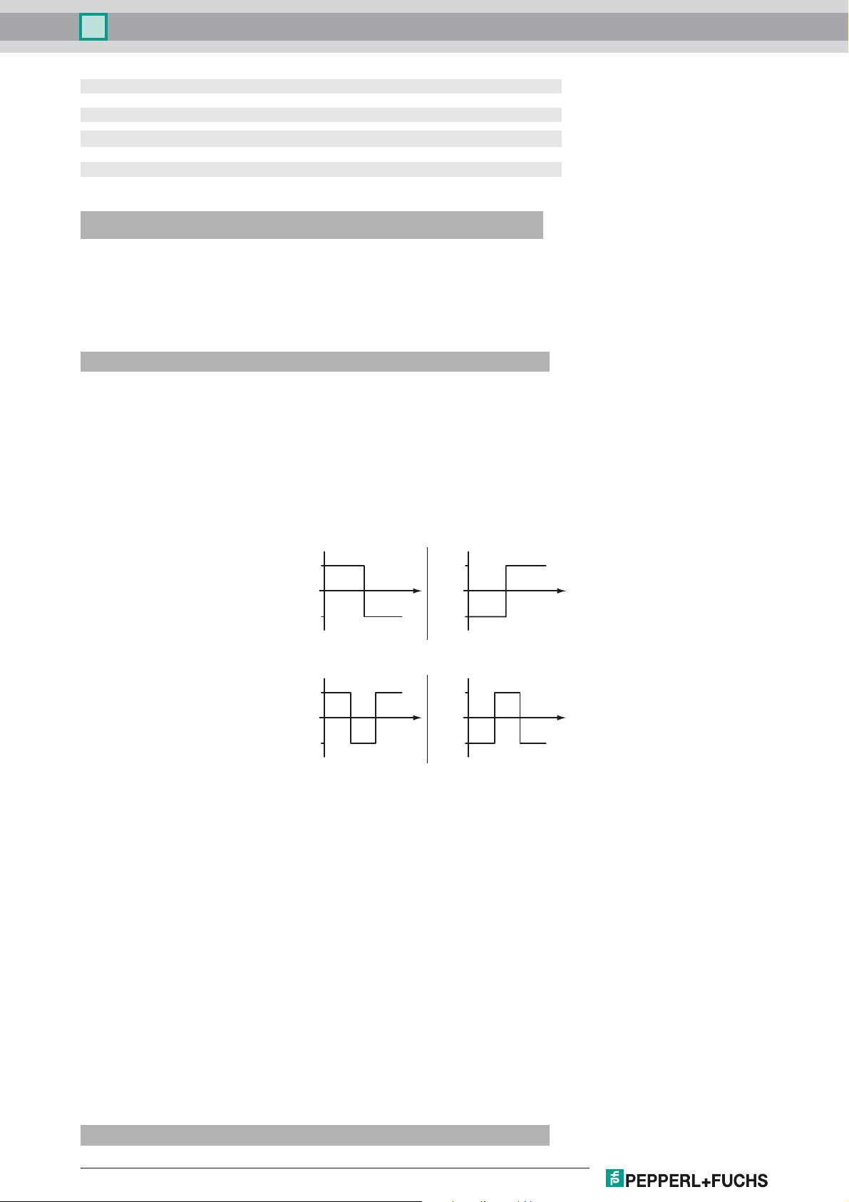
Set switching mode: you can define different switching modes by teaching in the relevant distance data for switching thresholds A and B.
1. Single point mode:
A leer
B
B leer
A
2. Window mode:
A > B
BA
B > A
AB
Teach in switching thresholds: you can teach in or overwrite a taught-in switching threshold at any time. To do this, press the "TI" button again.
Reset a value: you can reset a taught-in value. To do this, press the "TI" button for > 4 s, until the yellow and green LEDs go out. The reset
process itself starts when the "TI" button is released.
• Reset successful: the yellow and green LEDs flash alternately at 2.5 Hz.
Minimum and maximum values for the analog output Q2 are taught in and deleted in the same way as those for the switching output.
The following applies:
A = Minimum voltage/current
B = Maximum voltage/current
Resetting to Factory Settings
To revert back to factory settings, press the "TI" button for > 10 s with the rotary switch set to position "O," until the yellow and green LEDs go out
at the same time. The reset process itself starts when the "TI" button is released.
• Reset to factory settings successful: the yellow and green LEDs light up at the same time. The sensor then continues to operate with factory
settings.
OMT-IEP
• Factory setting for switching signal Q1:
Switching signal is high active, window mode
• Analog output: current output, 4 mA ... 20 mA absolute mode
OMT-UEP
• Factory setting for switching signal Q1:
Switching signal is high active, window mode
• Analog output: voltage output, 0 V ... 10 V absolute mode
Analog output
Release date: 2019-02-11 10:57 Date of issue: 2019-10-31 295670-100253_eng.xml
Refer to "General Notes Relating to Pepperl+Fuchs Product Information".
USA: +1 330 486 0001 Singapore: +65 6779 9091
Germany: +49 621 776 1111Pepperl+Fuchs Group
3
Page 4
Distance sensor
The analog output type can be configured as voltage or current output via IO-Link.
The following output types are available:
• Analog output 0 mA ...20 mA
• Analog output 4 mA ...20 mA
• Analog output 0 V ...10 V
The following operating modes are available:
• Absolute mode (default setting)
• Normalized mode
• Rising slope
• Falling slope
The following substitute values can optionally be configured:
• No substitute values used (default setting)
• Substitute value for "no measured value" used
• Substitute value for "no measured value" and "Measuring overrange" used
The sensor's tolerances are based on the digital process data.
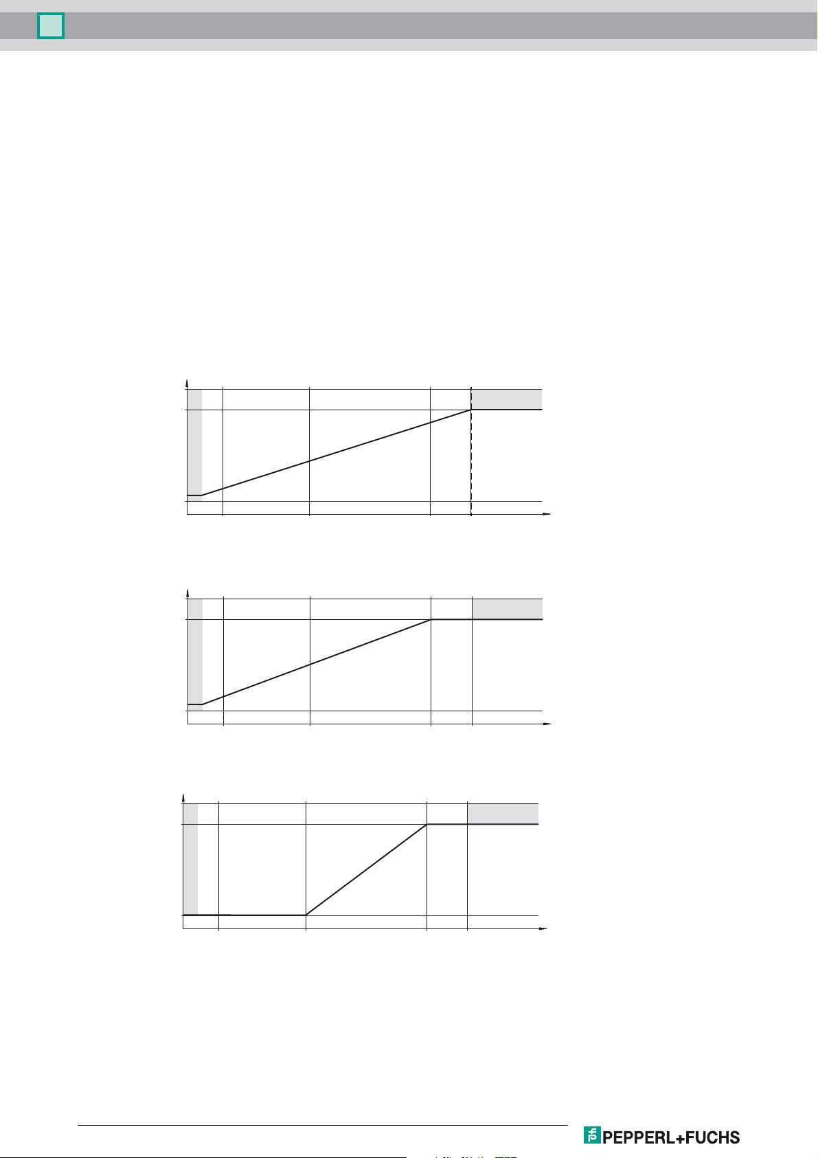
Absolute mode (default setting, A and B = deleted)
Analog value
OMT550-R200-IEP-IO-V1
No measurement data
No measurement data
0
Normal mode ( A and B without teach-in / deleted)
Analog value
No measurement data
0
A/B
Rising slope (A < B)
Analog value
DistanceMax. distanceMin. distance
No measurement data
DistanceMax. distanceMin. distance
No measurement data
No measurement data
0
Refer to "General Notes Relating to Pepperl+Fuchs Product Information".
4
USA: +1 330 486 0001 Singapore: +65 6779 9091
AB
Germany: +49 621 776 1111Pepperl+Fuchs Group
DistanceMax. distanceMin. distance
Release date: 2019-02-11 10:57 Date of issue: 2019-10-31 295670-100253_eng.xml
Page 5
Distance sensor
Falling slope (A > B)
Analog value
OMT550-R200-IEP-IO-V1
No measurement data
No measurement data
0
BA
DistanceMax. distanceMin. distance
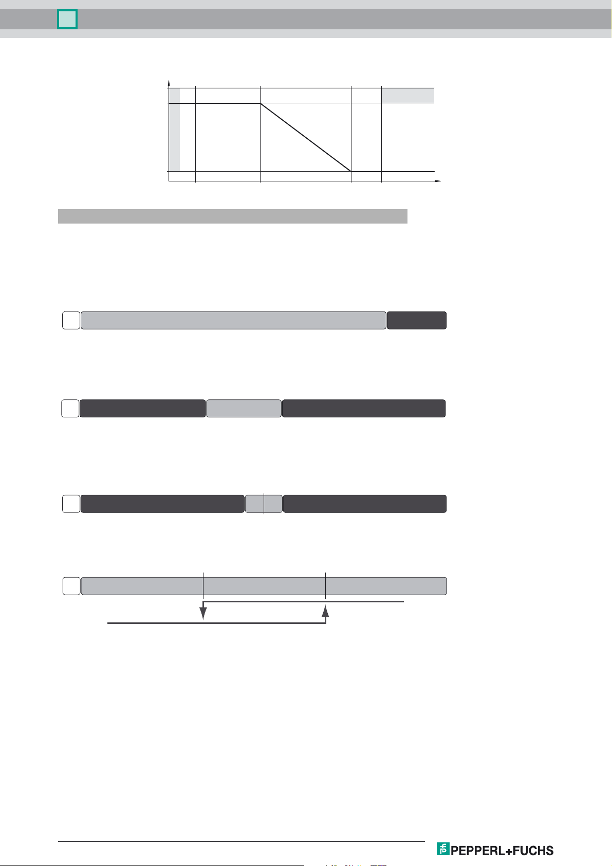
Configuration via IO-Link interface
Setting different operating modes via the IO-Link interface
The devices are equipped with an IO-Link interface as standard for diagnostics and parameterization tasks to ensure optimum
adjustment of the sensors to the relevant application.
Single point mode operating mode (one switch point):
• "Detection of objects irrespective of type and color in a defined detection range. Objects in the background are suppressed.
• "The switch point corresponds exactly to the set point.
active detection range
Background
suppression
Window mode operating mode (two switch points):
• Detection of objects irrespective of type and color in a defined detection range. Reliable detection when object leaves the detection range.
• Window mode with two switch points.
active detection range
Background suppressionForeground suppression
Center window mode operating mode (one switch point):
• Detection of objects irrespective of type and color in a defined detection range. Sets a defined window around a given object. Objects outside
this window are not detected.
• Window mode with one switch point.
active detection range
Background suppressionForeground suppression
Two point mode operating mode (hysteresis operating mode):
• Detection of objects irrespective of type and color between a defined switch-on and switch-off point.
active detection range
Output
Output
Inactive operating mode:
• Evaluation of switching signals is deactivated.
The associated IODD device description file can be found in the download area at www.pepperl-fuchs.com.
Hysteresis
Release date: 2019-02-11 10:57 Date of issue: 2019-10-31 295670-100253_eng.xml
Refer to "General Notes Relating to Pepperl+Fuchs Product Information".
USA: +1 330 486 0001 Singapore: +65 6779 9091
Germany: +49 621 776 1111Pepperl+Fuchs Group
5
 Loading...