

Page 1

2-D Laser Scanner
OMD10M-R2000-B23,
OMD30M-R2000-B23,
OMD12M-R2000-B23
FACTORY AUTOM ATION
MANUAL
Page 2

With regard to the supply of products, the current issue of the following documen t is applicable: The
General Terms of Delivery for Products and Se rvices of the Electrical Industry, published by the
Central Asso ciation of the Electrical Indus try (Zentralverband Elektrotechnik und Elektroindustrie
(ZVEI) e.V.) in its most recent version as well as the supplementary clause: "Expanded reservation
of proprietorship"
2-D Laser Scanner
Page 3

2-D Laser Scanner
Contents
2016 -01
3
1 Introduction......................................................................... 5
1.1 Introduction ...................................................................................................5
1.2 Validity ..........................................................................................................5
2 Declaration of Conformity ................................................. 6
3 Safety................................................................................... 7
3.1 Symbols Relevant to Safety ..........................................................................7
3.2 General Safety Information ............................................................................7
3.3 Laser Class 1 ................................................................................................8
3.4 Intended Use ................................................................................................8
4 Product Description ........................................................... 9
4.1 R2000 Laser Scanner ...................................................................................9
4.2 Functional Principle.....................................................................................10
4.3 Indicators and Controls ...............................................................................10
4.4 Interfaces and Connections ........................................................................11
4.5 Scope of Delivery........................................................................................12
4.6 Accessories ................................................................................................ 12
5 Installation......................................................................... 14
5.1 Storage and Transport................................................................................. 14
5.2 Unpacking...................................................................................................14
5.3 Mounting..................................................................................................... 14
5.4 Device Connection...................................................................................... 16
6 Commissioning................................................................. 17
6.1 Ethernet Configuration ................................................................................17
7 Operation........................................................................... 19
7.1 Menu Structure ........................................................................................... 19
7.2 Operation ....................................................................................................21
7.3 Description of Menu Items ..........................................................................24
7.3.1 Ethernet Info Menu Item .........................................................................24
7.3.2 Ethernet Setup Menu Item ......................................................................24
7.3.3 Sensor Setup Menu Item ........................................................................ 25
7.3.4 Demos Menu Item .................................................................................. 26
7.3.5 Tools Menu Item .....................................................................................26
7.3.6 End Menu Item .......................................................................................26
8 Maintenance and Repair.................................................. 27
8.1 Maintenance ...............................................................................................27
8.2 Repairs .......................................................................................................27
Page 4

2016 -01
4
2-D Laser Scanner
Contents
9 Troubleshooting ............................................................... 28
9.1 Troubleshooting.......................................................................................... 28
10 Appendix........................................................................... 29
10.1 Technical Data Daten "Ultra High Density" Models ..................................... 29
10.2 Technical Data "High Density" Variants ...................................................... 32
10.3 Amplitude Characteristics .......................................................................... 35
10.4 Pulse Ranging Technology (PRT) Glossary................................................ 37
10.5 Using Open Source Programs.................................................................... 37
Page 5

2-D Laser Scanner
Introduction
2016 -01
5
1 Introduction
1.1 Introduction
Congratulations
You have chosen a device manufactured by Pepperl+Fuchs. Pepperl+Fuchs
develops, produces and distribu tes e lectronic sensors and interface modules for
the market of automation technology on a worldwide scale.
Read these instructions carefully before you install this device and put it into
operation. Instructions and hints included in this manual lead you step by step
through the installation and commissioning and provide a trouble-free use of this
product. This is for your benefit, since this helps you to:
■ ensures the safe operation of the device
■ ex ploit the full functionality of the device
■ avoid operating errors and related disturbances
■ avoid costs due to disruptions and repair work
■ increase the effectiveness and efficiency of your system.
Keep these instructions for reference for later work on the equipment.
Please check after opening the package, that the device isn 't damaged and the
completeness of the delivered goods.
Symbols used
The following symbols are used in this manual:
Handling instructions
You will find handling instructions beside this symbol
Contact
If you have any questions about the device, its functions, or accessories, please
contact us at:
Pepperl+Fuchs GmbH
Lilienthalstraße 2 00
68307 Mannheim
Telephone: +49 62 1 776-4411
Fax: +49 621 776-274411
E-Mail: fa-info@pe pperl-fuchs.com
1.2 Validity
This manual applies to devices from firmware 1.20 and hardware 1.00 o nward.
The versions can be found in the device menu; see chapter 7.3.3.
For devices with older versions, documentation is available on request.
Note!
This symbol draws your attention to important information .
Page 6

2016 -01
6
2-D Laser Scanner
Declaration of Conformity
2 Declaration of Conformity
All products were developed and manufacture d under observance of the
applicable European standards and guidelines.
The product manufacturer, Pepperl+Fuchs GmbH, 68307 Mannheim, has a
certified quality assurance system that conforms to ISO 9001.
Note!
A Declaration of Conformity can b e requested from the manufacturer.
ISO9001
Page 7

2-D Laser Scanner
Safety
2016 -01
7
3 Safety
3.1 Symbols Relevant to Safety
3.2 General Safety Information
The following basic instructions must be o bserved at all times:
■ The device must not be commissioned until the manual has been read and
understood
■ The power supply to produce the supply voltage must have a safe electrical
isolation by means of double insulation and a safety transforme r according
to DIN VDE 05 51 (corresponds to IEC 742)
■ The device must not be used outside of its specification withou t suitable
protective measures
■ Modifying the device is not permitted
■ Do not point the devices in direct sunlight and do not take meas urements in
sunlight
■ Do not remove the warnings or rating plates
Installation and commissioning of all devices mus t be performed only by
personn el specially trained for that purpose.
Protection of operating personnel and the system is not ensured if the product is
not used in accordance with its intended use.
The laws and guidelines applicable for the use or the intended purpose must be
observe d. Devices are approved only for prope r usage in accordance with
intended use. Ignoring these instructions will void any warranty and absolve the
man ufacturer from any liability.
Use only recommended original accessories.
Danger!
This symbol indicates an imminent danger.
Non-observance will result in personal injury or death.
Warning!
This symbol indicates a possible fault or danger.
Non-observance may cause personal injury or serious property damage.
Caution !
This symbol indicates a possible fault.
Non-observance could interrupt the device and any connected systems and
plants, or result in their complete failure.
Page 8

2016 -01
8
2-D Laser Scanner
Safety
If you are unable to resolve faults, switch the device off. Make sure that the device
cannot be switched back on accidentally. If the device needs to be repaired,
return it to Pepperl+Fuchs. If you o pen or modify the device yourself, not only are
you endang ering yourself and others but you will void any warranty and absolve
the manufacturer from any liability.
Dispos e of unusable devices in accordance with the a pplicable national statutory
regulations.
For instan ce, you can take the sensor to a designated collection point for
electronic waste.
3.3 Laser Class 1
Class 1 Laser Product
This sensor is certified according to laser protection class 1.
3.4 Intended Use
The R2000 laser scanners are measuring devices that are used on automated
transport systems or other movable machinery in intralogistics. They a re also
used on stationary equipment in the area of factory a nd building automation.
Make su re that the devices are used only for their intended purpose.
Danger!
In applications involving stock feeders a nd moving carriages, care mu st be taken
to ensu re that the applicable safety regulation s are obs erved at all times.
Failure to do so may result in serious or fatal injury!
Warning!
Class 1 lase r light
The laser light can be an irritant, especially in a dark environment. Do not point
lasers at people!
Maintenance and repairs should only be carried out by authorized service
person nel!
Install the device so that the warning is clearly visible and readable.
Caution : Use of controls, adjustments, or performance of procedures other than
those s pecified herein may result in harmful laser beam exposure.
Page 9

2-D Laser Scanner
Product Description
2016 -01
9
4 Product Description
4.1 R2000 Laser Scanner
The two-dimensional R2000 laser scan ner is made up of a static body, on which a
continuously turning me asurement module with an emitter laser and receiver
element is located. The laser scanner uses Pulse Ranging Technology (PRT).
The implementation of this innovative operating principle permits unbroken
scan ning of the surroundings through a full 360°.
As a compact 360° scanner with high measuring frequen cy, small angular
reso lution, precise light spot, visible measurement beam (OMD10M-R20 00-B23),
and an integrated all-round display, the system can be used in numerous
applications in factory au tomation. In addition to completing familiar tasks from
industrial areas such as logistics, transportation, and material handling, the
system can be used for innovative ap plications in buildings automation, automatic
navigation of autonomous vehicles, or for monitoring rooms.
One particular highlight of the laser scanner is the row of LEDs arranged on the
back of the measurement module. Rotating the scanner produces a cylindershaped projection surface, wh ich is su itable for displaying text-based as well as
graphical information. In this way, commissioning and operations can be carried
out without aids such as a PC or Notebook . Operating and diagnostic information
can be seen directly during ongoing o peration.
The laser scanner from the R2000 se ries fulfills the safety requirements of laser
class 1 in measurement mode. The low amount of laser light emitted guarantees
that operating personnel are neithe r injured nor harmed.
Page 10
2016 -01
10
2-D Laser Scanner
Product Description
4.2 Functional Principle
The laser scanner works according to the principle of Pulse Ranging Technology
(PRT). As part of this principle, the time between sending a light pulse and
receiving the reflected pulse from an object is measured in the device. Due to the
constan cy of the speed of light, this time is a measurement of distance.
In comparison with other distance measurement processes, run time
measurement is affected very little by any disturbances in the measu ring
environment. As a result, this measurement process can be used with a high level
of accuracy even under tough everyday industrial conditions. The light source and
light receiver are located in the rotating sensor head.
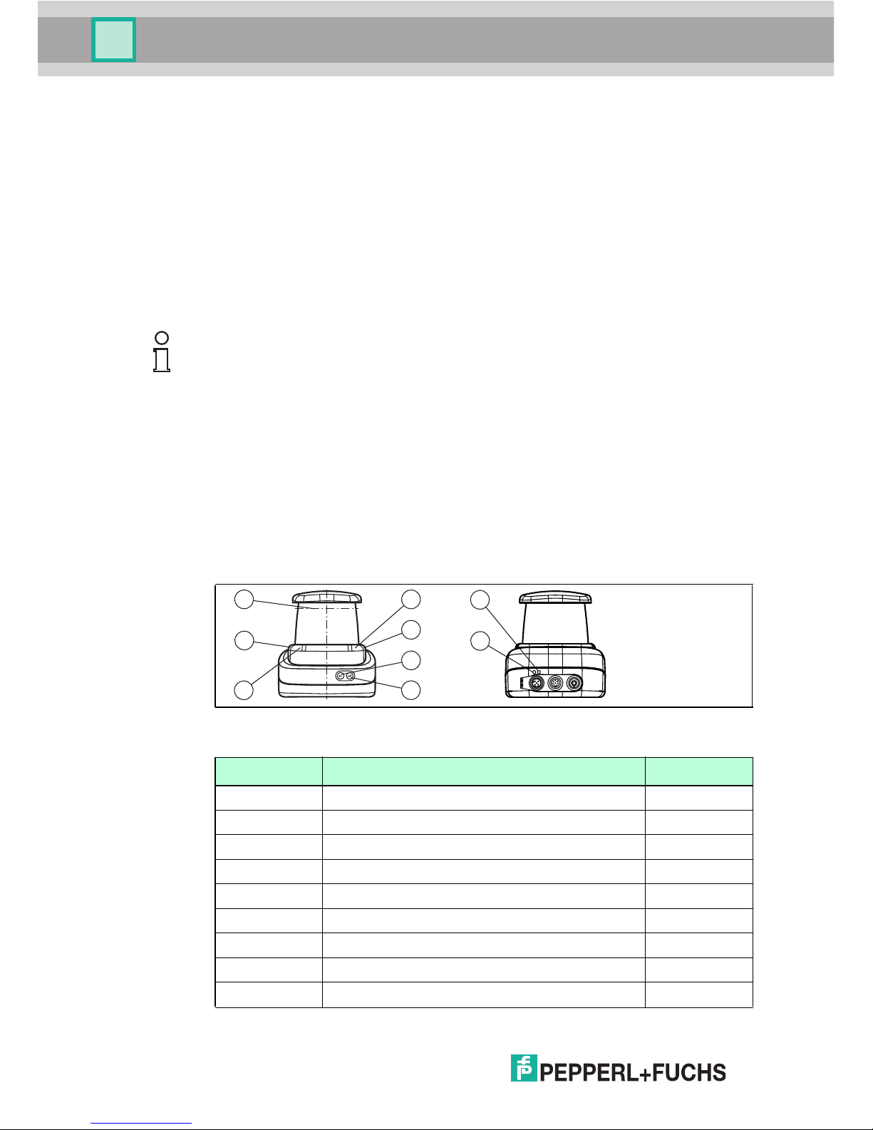
4.3 Indicators and Controls
Figure 4.1 Indicators and Controls
Note!
Influence of ambient conditions
The speed of light depends on the air temperature and barometric pressure.
The influence of the air temperature amounts to 1 pp m/K.
The influence of the barometric pressure amo unts to -0.3 ppm/hPa.
These faults must be taken into consideration b y the use r in the case of longer
distances.
In the operating range (-10 °C ... +50 °C) this fault amo unts to 0.6 mm at a
distance of 10 m.
No. Designation Color
1 Operating status indicator Green
2 Error indicator Red
3 "Next" menu button
4 "Return" menu button
5 Q2 - no function
6 Q1 - no function
7 Laser face
8 Ethernet link ind icator Green
9 Ethernet activity indicator Yellow
Table 4.1 Indicators and Controls
2
6
1
4
3
5
7
9
8
Page 11

2-D Laser Scanner
Product Description
2016 -01
11
4.4 Interfaces and Connections
The following connections are found on all devices:
Power supply
There is a 4-pin M12 connector on the rear of the housing to connect the power
supply. The following diagram shows the p inning:
Figure 4.2 Power supply connectio n layout
MultiPort
The 8-pin M12 connector on the rear of the housing is for service purposes.
Interface:
There is a 4-pin M12 socket on the back of the housing to connect the Ethernet
interface. The following diagram shows the pinning:
Figure 4.3 Ethernet conne ction layout
The connector h ousing is located on the shield.
1 24 V pow er supply
2 Not used
3 Ground (GND)
4 Not used
1 TD+
2 RD+
3 TD-
4 RD-
1
3
4
2
1
4
6
7
8
53
2
1
3
4
2
Page 12
2016 -01
12
2-D Laser Scanner
Product Description
4.5 Scope of Delivery
The scope of delivery includes:
■ R2000
■ Quick start guide
■ Protective cover
■ 3 x socket cap screws, M5 x 10
■ 3 x washers, size 5
4.6 Accessories
The following products are availab le as accessories.
Note!
Installation Instructions for North America
If a connection is made to the M12 multi-pin connector, the product shall be use d
with a UL-listed cable/connector (CYJV) assembly rated minimum 30 VDC,
minimum 1.0 A, in the final installation for power supply.
Designation Description
V1SD-G-2M -PUR -ABG-V45-G Patch cable M12 to RJ45, len gth 2 m
V1SD-G-5M -PUR -ABG-V45-G Patch cable M12 to RJ45, len gth 5 m
V1SD-G-ABG-PG9 Single-ended male co rdset, M12 D-coded, 4-pin for
bus cable
V1-G-2M-PUR Single-ended female cordset, straight, M12 , 4-pi n,
PUR cable
V1-W-2M-P UR Single-ended female cordset, angled, M12, 4-pin,
PUR cable
MH-R2000 Mounting bracket, quick-lock and adjustment aid
Note!
Installation Information for North America
If a connection is made with the M1 2 multi-pin connector, then in the final
installation of the power supply, the product must be used with a UL-listed
cable/conn ector assembly (CYJV) that is designed for at least 30 VDC and at least
1.0 A.
Designation D escription
V1-G-BK-2M-PUR -U Single-ended female cordset, straight, M12, 4-pin,
PUR cable, leng th 2 m, "UL recognized"
V1-G-BK-5M-PUR -U Single-ended female cordset, straight, M12, 4-pin,
PUR cable, leng th 5 m, "UL recognized"
V1-G-BK-10M -PUR -U Single-end ed female cordset, straight, M12, 4-pin,
PUR cable, leng th 10 m, "UL recognized"
Page 13

2-D Laser Scanner
Product Description
2016 -01
13
To parameterize the 2-D laser scanner conveniently via a software interface, you
need the corresponding device type manager (DTM) in addition to the FDT
framework program (PACTware 4.x). Both PACTware and the DTM are available at
www.pepperl-fuchs.com.
Page 14

2016 -01
14
2-D Laser Scanner
Installation
5 Installation
5.1 Storage and Transport
Package the device for storage and transport such that it is protected from impact
and moisture. The original packaging provide s optimum protection. Also take note
of the permitted ambien t conditions.
5.2 Unpacking
Check the product for damage while unpacking. In the even t of damage to the
product, inform the post office or parcel service and notify the supplier.
Retain the original packaging in case the device mus t be stored o r shipped again
at a later date.
Should you have any questions, please direct them to Pepperl+Fuchs.
5.3 Mounting
The device can be fitted with the supplied socket head screws with washers on
the underside of the device.
Note!
If the temperature is s ubject to major fluctuations during transport, the device
must be allowed to a cclimatize for around two hours prior to installation and use.
During this acclimatization period, avoid subjecting the device to condensation at
all costs, as this could have an effect on intern al parts and cause damage.
Caution!
Safety information
Do not point the sensor into the sun.
Protect the sensor against direct and prolonge d su nlight.
Prevent condensation from forming by ensuring that the sensor is not subjected to
any major temperature fluctuations.
Do not subject the sensor to aggressive chemicals.
Keep the glass on the device clean.
For clea ning, use only water (if necessary with a little detergent) and a soft
microfiber cloth! The use of other detergents is not permitted! The glass must
never be cleaned when dry!
Caution!
Screw-in depth
The maximum screw-in depth in the base must not exceed 8 mm, otherwise the
device will be mechanically destroyed! The minimum screw-in depth is 5 mm.
Page 15

2-D Laser Scanner
Installation
2016 -01
15
Figure 5.1 Dimensional drawing R2000
70
(40)20
60
20
53
106
117.5
4658
116.5
106
16
97.1
3 x M5
20
45
Emitter range and receiver range
Complies with 21 CFR
1040.10 and 1040.11 except
for deviations pursuant to
Laser Notice No. 50,
dated June 24, 2007
CLASS 1
LASER PRODUCT
IEC 60825-1: 2007 certified.
Note!
Keep the emitting/receiving area clear
During assembly, make sure that the emitting/receiving area is kept clear. If the
emitting /receiving area is covered, this reduces the performance of the 2D laser
scan ner.
Page 16

2016 -01
16
2-D Laser Scanner
Installation
5.4 Device Connection
Electrical connection in line with IP65
Put protective cove rs on unused M12 conne ctors.
The IP65 protection class is achieved. The protective covers can be ordered
as accessories see chapter 4.6.
The device conforms to protection class III. This means that the power has to be
supplied as a low protective voltage (PELV).
The power supply of the device is 10 VDC ... 30 VDC. Due to the integrated motor,
an increase d level of startup current is required compared with no rmal op eration.
It is recommended that power sup plies with 1 A (at 24 V) or with 2 A (at 12 V) are
used.
The maximum cable length is 3 0 m.
The pin assignment is as follows:
Figure 5.2 R2000 pin assignment
PowerMultiportLAN
4
1
2
3
TD+
TD-
RD-
Shield
4
1
2
3
24 V DC
0 V
RD+
Shield
1
3
4
2
1
3
4
2
Page 17

2-D Laser Scanner
Commissioning
2016 -01
17
6 Commissioning
1. Connect the device to the power supply.
The initialization phase lasts approx. 15 seconds. This ph ase is sh own by
circles moving down the display.
2. After the initialization p hase, the Pepperl+Fuchs logo will appear.
The device is now ready for operation.
To achieve the best measure ment accuracy, allow the device to warm up for 30
minutes.
The sensor has bee n tested and calibrated before delivery. It can be put into
operation immediately.
In general, it is recommended to u se a dedicated network card for the conn ection
to the device.
6.1 Ethernet Configuration
The device has three different address modes. Select your preferred mode from
the modes described below. The setting is configured directly on the device using
the menu interface.
Auto IP
In this mode, the device independently selects a "Link-Local" IP address in the
169.25 4.0.0/16 range. It is ens ured that the selected address is not already being
used by another device.
The device is configured to Auto IP by default. The Auto IP setting is the ideal way
to establish a direct connection to a PC. Set the DHCP mode (Dynamic Host
Configuration Protocol) on the PC. To do this, select the TCP/IP protocol in the
network card properties and select the "Obtain an IP address automatically"
setting there. After approx. 30 seconds, Windows assigns an Auto IP for the PC.
Page 18

2016 -01
18
2-D Laser Scanner
Commissioning
DHCP
Set the device to DHCP under the "Address mode" menu item. The DHCP
configuration requires a DHCP server in the local network, e.g., a router. See the
"Auto IP" item for information on this.
Manual IP
Set the device to manual under the "Address mode" menu item. The IP address is
set to 10.0.10.9 and the subnet mask to 255.0.0.0 by default. To conne ct the
device to the PC, the network card must be configured as fo llows. Set the required
IP address in the network card menu. Select the TCP/IP protocol in the network
card properties and select the "Use the following IP addres s" setting there. Enter
the required IP address and subnet mask in these fields.
Note!
Device restart
Yo u must restart the device after ch anging the Ethernet configuration.
Page 19

2-D Laser Scanner
Operation
2016 -01
19
7 Operation
7.1 Menu Structure
Menu
Adress Mode
IP Address
Gateway
MAC Address
Back
Ethernet Info
Adress Mode
IP Address
Gateway
Reboot
Back
Ethernet Setup
Manuel
DHCP
Back
Auto IP
Subnet Mask
Subnet Mask
Page 20

2016 -01
20
2-D Laser Scanner
Operation
Language
Display mode
Version Info
Factory Defaults
Sensor Setup
Firmware
Hardware
PFSDP
Back
English
German
Back
Display Off
Static Logo
Bargraph distance
Bargraph reflector
Static Text
Application bitmap
Application text
Back
Bargraph echo
Load
Back
Page 21

2-D Laser Scanner
Operation
2016 -01
21
7.2 Operation
The sensor is operated using two buttons, located on the front of the sen sor, with
which you can navigate in the menu structure. You can change the parameters or
enter values u sing these buttons.
Meaning of Buttons
Sensor eyes
Tape measure
Demos
Back
Alignment aid
Tools
End
This button is used as the "Next" button. Pressing this butto n
takes you to the next menu item. You can change a value wit h
this button.
This button has a sim ilar function to the ARRO W button on
the computer keyboard.
Pressing this butto n selects the displayed menu item.
This button has a similar function to the ENTER button on the
computer keyboard.
Page 22

2016 -01
22
2-D Laser Scanner
Operation
In each menu item, the values already set are displayed with an underscore.
These values can be cha nged. However, please note that thes e values should
only be changed by personn el with the ne ces sary expe rtise on the imp act of the
change.
If no other button is pressed within 60 seconds in the menu levels, the menu is
ended automatically.
Navigation in the Menu
Change count parameters
Menu display
Top row The current menu level is shown in the top row.
Bottom row The currently sel ected element is shown in the botto m row.
Dash One dash means that you are in the main menu.
Two dash es me an that you are in the submenu.
Operation
Pressing the ENTER butto n takes you into the menu structure.
You change to the next menu eleme nt.
If you hold down (> 1 second) the "Next" button or "ENTER"
button, you will change to the next higher menu element.
You change to the selected menu element
If you hold down (> 1 second) the "Next" button or "ENTER"
button, you will change to the next higher menu element.
Menu entry
End This menu entry e nds the main menu.
Back This menu e ntry changes to the next higher menu element
Menu display
Top row This shows the current parameter.
Bottom row This shows the currently selected parameter value.
Underli ned parameter
value
This is the currently activated value.
Operation
You change to the next available parameter value.
If you hold down the button (> 1 second), you will change to
the next highe r menu element without changing the
parameter.
You activate the parameter value currently displayed.
If you hold down the button (> 1 second), the displayed
parameter is activated and the displ ay returns to the higherlevel menu ele ment.
Page 23

2-D Laser Scanner
Operation
2016 -01
23
Changing Numerical Parameters
IP Configuration Display
Back Menu Item
You return to the higher-level menu via the "Back" men u item
Menu display
Top row Th is shows the name of the displayed p arameter.
Botto m row This shows the curren t value of the parameter.
Underline d p arameter
value
This is the parameter value currently being edited.
Operation
You increase the currently selected digit.
If you hold down the button (> 1 second), you increase the
selected digit at a faster rate
You chang e to the next editable digit.
If you hold down the button (> 1 second), you change to the
confirm menu.
Confirm menu
Top row Th is shows the changed number.
Botto m row This shows the action s that can be carried out (Save, Edit,
Cancel).
"Save" action The changed value is accep ted and saved.
"Edi t" action You change back to the edit display.
"Cancel" action The changes are rejected and you change to the higher-level
menu.
Menu display
Top row Name of the displayed parameter.
Botto m row This shows the curren t value of the parameter.
Operation
You chang e to the next menu element.
If you hold down (> 1 second) the "Next" button o r "ENTER"
button, you will change to the next higher menu element.
no function
If you hold down (> 1 second) the "Next" button o r "ENTER"
button, you will change to the next higher menu element.
Page 24

2016 -01
24
2-D Laser Scanner
Operation
7.3 Description of Menu Items
7.3.1 Ethernet Info Menu Item
This menu item provides fast access to the IP configuration currently in use. The
data can be read only in this menu item.
Address Mode
The address mode currently being used is displayed in this subitem.
IP Address
The IP address currently being used is displayed in this subitem.
Subnet Mask
The subnet mask currently being used is displayed in this subitem.
Gateway
The gateway currently being used is displayed in this subitem.
MAC Address
The MAC address currently being u sed is displayed in this subitem.
7.3.2 Ethernet Setup Menu Item
Chang e the IP configuration data in this menu item.
Address Mode
■ "Manue l": Here an IP address, the subnet mask, and the gateway can be
assign ed manually to the device
■ "DHCP": Th e device is assigned an IP address by a DHCP server (e.g.,
Windows PC)
■ "AutoIP": The device can be detected automatically by the PC
IP Address
The IP address to be used in the address mode : "Manual" can be set in this menu
item.
Subnet Mask
The subnet mask to be used in the address mode: "Manual" can be s et in this
menu item.
Gateway
The Gateway can be set in this menu item.
Note!
Changing the IP Configu ration
Chang es to the IP configuration take effect on ly after a restart! The IP
configuration currently used by the device is displayed in the "Ethernet Info" menu
item. If these settings differ from the settings made under the "Ethernet Setup"
menu item, the device must be restarted.
Page 25

2-D Laser Scanner
Operation
2016 -01
25
Reboot
The device can be restarted in this menu item.
7.3.3 Sensor Setup Menu Item
Language
The language can b e set to German or English using this menu item.
Display mod e
The display mode defines the display in normal mode w hen the menu is not
active. The display mode is set on a permanent basis. It is active following a
restart.
■ Display off: The display goes dark as soon as the menu is exited.
■ Static logo: The display shows the Pepperl+Fuchs logo. The log o can be
replaced with a custom bitmap file that will still be available after switching
the device on/off (saved in EEPROM). See the Ethernet protocol
description for details on programming .
■ Static text: The display shows the text "Pepperl+Fuchs R2000". The text
can be replaced with custom text that will still be available after switching
the device off/on (saved in EEPROM). See the Ethernet protocol
description for details on programming .
■ Bargraph distance: The display shows a bar graph indicating the
distance. The measured values in all directions are shown in the form of a
bar chart. The bars become s maller as the distance increase s.
■ Bargraph reflector : A ba r is shown on the display at the point at which a
reflector is detected.
■ Bargraph echo: The measured signal strength is shown in the form of a
graph on the display.
■ Application bitmap: A custom bitmap file (24x252 bit) is show n on the
display that is no long er available after switching off the device (saved in
RAM). See the Ethernet protocol description for details on programming.
■ Application text: Custom text is shown on the display that is no longer
available after switching off the device (saved in RAM). See the Ethernet
protocol description for details on p rogramming.
Note!
Changing the IP Configuration
Change s to the IP configuration take effect only after a restart! The IP
configuration currently used by the device is displayed in the "Ethernet Info" menu
item. If these settings differ from the settings made under the "Ethernet Setup"
men u item, the device must be restarted.
Note!
The Static logo and Static text display modes are suitable for infrequent
changes to the logo and text data.
The Application bitmap and Application text display modes are suitable for
frequent changes to the logo and text data.
Page 26

2016 -01
26
2-D Laser Scanner
Operation
Version Info
■ Firmware: The display shows the current version of the firmware.
■ Hardware: The display shows the current version of the hardware.
■ PFSDP: The display shows the current version of the Pepperl+Fuchs Scan
Data Protocol.
Factory defaults
The factory defaults for the sensor can be loaded in this menu item. To do th is, you
must select "Loa d" in the submenu an d confirm by pressing the "Enter" button.
Yo u must restart the device to accept all the changes.
7.3.4 Demos Menu Item
A demo is only active temporarily. As soon as an other option is selected in the
menu, the demo becomes inactive. This a lso applies to res tarting.
Sensor Eyes
A pair of eyes, which focuse s on moving objects, appears o n the display. If no
activity is detected within five seconds, the "eyes" close. If scanner movement is,
in fact, detected, the "eyes" open again.
Tape Measure
In this demo, the scanner measures the distance in a forward direction (x-axis).
The value is then shown in the display.
7.3.5 Tools Menu Item
Alignment aid
A bar is shown on the display at the point at which a reflector is detected. An
angular scale is shown at the bottom of the display. The "Alignment aid" tool is
automatically exited after approximately ten minutes an d the stored display mode
is activated.
7.3.6 End Menu Item
End
Pressing the "Enter" button to confirm ends the menu and the display mode set is
displayed.
Page 27

2-D Laser Scanner
Maintenance and Repair
2016 -01
27
8 Maintenance and Repair
8.1 Maintenance
Observe the applicable nation al regulations whe n maintaining the sensor.
Essentially, the sensor is maintenance free. Nonetheless, check the technical
safety of the se nsor system at regular intervals by loo king for damage to the
housing . Ch eck the sens or for dirt every now and then. To clean the sensor, wipe
it at regular intervals with a dry or damp soft cloth. This will ensure it continues to
function properly. The housing is made of plastic. For this reason, do not use
acetone or detergents containing solvents.
8.2 Repairs
If it appears that safe operation of the system is no longer possible, the system
mus t be taken out of operation and steps taken to prevent it being used
inadvertently. If the device needs to be repaired, return it to Pepperl+Fuchs. If you
open or modify the device yourself, not only are you endan gering yourself and
others but you will void any warranty and absolve the manufacturer from any
liability.
Page 28

2016 -01
28
2-D Laser Scanner
Troubleshooting
9 Troubleshooting
9.1 Troubleshooting
Interference
■ The sensor must be firmly mounted. It must not vibrate.
■ The sensor must not be installed behind a cover.
■ The sensor should be installed so it is protected from rain.
Note!
When carrying out the insulation measurement, be aware that suppressor diodes
have been installed for electromagnetic compatibility.
Page 29

2-D Laser Scanner
Appendix
2016 -01
29
10 Appendix
10.1 Technical Data "Ultra High Density" Models
General specifications
Functional safety related parameters
OMD10M-R2000-B23-*
Standard Range
OMD30M-R2 000-B23-*
Long Rang e
OMD30M-R2000-B23-*-T-*
Long Range, cold store
Measurement range 0.2 ... 3 m (bk 10%)
0.2 to 10 m (wh 90%)
0.2 to 60 m (reflector)
0.1 ... 10 m (bk 10%)
0,1 30 m (wh 90 %)
0,1 100 m (reflector)
0.1 ... 10 m (bk 10%)
0,1 30 m (wh 90 %)
0,1 100 m (reflector)
Light source laser diode laser diode laser diode
Light type modulated visible red
light
modulated infrared lig ht modul ated infrared light
Laser nominal
ratings
Note LASER LIGHT , DO
NOT STARE INTO
BEAM
LASER RADIATION ,
DO NOT STARE INTO
BEAM
LASER RADIATION , DO
NOT STARE INTO BEAM
Laser class 1 1 1
Wave length 660 nm 9 05 nm 905 nm
Beam divergence 1 mrad transversal 2 mrad ,
longitud inal 10 mrad
transversal 2 mrad ,
longitudinal 10 mrad
Pulse length 5 ns 5 ns 5 ns
Repetition rate 250 kHz 250 kHz 250 kHz
max . pulse energy < 4 nJ < 94 nJ < 94 nJ
Measuring method Pulse Ranging
Tec hnology (PRT)
Pulse Rangin g
Technology (PRT)
Pulse Ranging Technology
(PRT)
Scan rate
10 ... 50 s
-1
10 ... 50 s
-1
10 ... 50 s
-1
Scanning ang le 360° 360° 360°
Diameter of the light
spot
< 20 mm at 10 m 25 mm x 105 mm at 10 m25 mm x 105 mm at 10 m
Ambient light limit > 8000 0 Lux > 80000 Lux > 80000 Lux
Resolutio n 1 mm 1 mm 1 mm
OMD10M-R2000-B23
Standard Range
OMD30M-R 2000-B23
Long Range
OMD30M-R 2000-B23-*-T-*
Long Range, cold store
MTTF
d
75 a 75 a 75 a
Mission Time (TM) 20 a 20 a 20 a
Diagnostic Coverage
(DC)
0 % 0 % 0 %
Page 30

2016 -01
30
2-D Laser Scanner
Appendix
Indicators/operating means
Electrical specifications
Interface
Measurement accuracy
OMD10M-R20 00-B23
Standard Range
OMD30M-R2 000-B23
Long Rang e
OMD30M-R 2000-B23-*-T-*
Long Range, cold store
Operation indicator LED green L ED green LED green
Data flow indicator LED yellow: active
ethernet
LED green: Ethernet
link
LED yellow: active
ethernet
LED green: Ethernet
link
LED yell ow: active ethernet
LED green: Ethernet link
Function indicator LED red: fault
LED yellow: Q1 + Q2
LED red: fault
LED yellow: Q1 + Q2
LED red: fault
LED yell ow: Q1 + Q2
Control elements 2 Button 2 Button 2 Button
Parameterization
indicator
24 x 252 pixels , red 2 4 x 252 pixels , red 24 x 252 pixel s , red
OMD10M-R2 000-B23
Standard Range
OMD30M-R2000-B23
Long Range
OMD30M-R2000-B23-*-T-*
Long Range, col d store
Operating voltage 10 ... 30 V DC 10 ... 30 V 10 ... 30 V
Ripple 10 % within the supply
tolerance
10 % w ithi n the supply
tolerance
10 % within the supply
tolerance
No-load supply
current
≤ 400 mA / 24 V DC ≤ 400 mA / 24 V DC ≤ 400 mA / 24 V DC
Power consumption < 10 W < 10 W < 10 W
Time delay b efore
availability
< 40 s < 40 s < 40 s
OMD10M-R 2000-B23
Standard Range
OMD30M-R 2000-B23
Long Range
OMD30M-R2000-B23-*-T-*
Long Range, cold store
Interface type Fast Ethernet Fast Ethernet Fast Ethernet
Protocol HTTP , TCP/IP and
UDP/IP
HTTP , TCP/IP and
UDP/IP
HTTP , TCP/IP and UDP/IP
OMD10M-R 2000-B23
Standard Range
OMD30M-R2 000-B23
Long Rang e
OMD30M-R 2000-B23-*-T-*
Long Ran ge, cold store
Measuring speed 250000
measurements per
second
250000
measurements per
second
250000 measurements per
second
Measured value
noise
± 9 mm (1 sig ma, on
reflector film)
typ. ± 10 mm (1 sigm a;
max 20 mm; 0,1 m ... 8
m)
typ. ± 12 mm (1 sigm a;
max 20 mm; 8 m ...
100 m)
typ. ± 10 mm (1 sigma; max 20
mm; 0,1 m ... 8 m)
typ. ± 12 mm (1 sigma; max 20
mm; 8 m ... 100 m)
Angle resolution 0.014 ° 0.014 ° 0.014 °
Page 31

2-D Laser Scanner
Appendix
2016 -01
31
Ambien t conditions
Mechanical specifications
Compliance with standards and directives
Abs olute
accuracy
typ. ± 35 mm ty p. ± 25 mm ty p. ± 25 mm
Repeat accuracy < 12 mm < 12 mm < 12 mm
OMD10M-R20 00-B23
Standard Range
OMD30M-R2000-B23
Long Range
OMD30M-R20 00-B23-*-T-*
Long Range, co ld store
OMD10M-R20 00-B23
Standard Range
OMD30M-R 2000-B23
Long Ran ge
OMD30M-R 2000-B23-*-T-*
Long Range, cold store
Ambient tempe rature -10 ... 50 °C (14 ... 122
°F)
-10 ... 50 °C (14 ... 122
°F)
-30 ... 50 °C (-22 ... 122 °F)
Storage temperature -20 ... 70 °C (-4 ... 158
°F)
-20 ... 70 °C (-4 ... 158
°F)
-40 ... 70 °C (-40 ... 158 °F)
Relative humidity 95 % , no moisture
condensation
95 % , no moisture
condensation
95 % , no moisture
condensation
OMD10M-R20 00-B23
Standard Range
OMD30M-R2000-B23
Long Range
OMD30M-R 2000-B23-*-T-*
Long Range, cold store
Degree of
protection
IP65 IP65 IP67
Connection 4-pi n, M12x1 conn ector,
stand ard (supply) ,
8-pin, M12x1 conn ector,
A-cod ed (MultiPort) ,
4-pin, M12x1 socket, Dcoded (LAN)
4-pin, M12x1 connector,
standard (supply) ,
8-pin, M12x1 connector,
A-cod ed (MultiPort) ,
4-pin, M12x1 socket, Dcoded (LAN)
4-pin, M12x 1 connector,
standard (supply) ,
8-pin, M12x 1 connector, Acoded (MultiPort) ,
4-pin, M12x 1 socket, Dcoded (LAN)
Material
Housing ABS + PC + aluminum ABS + PC + aluminum ABS + PC + alumi num
Optical face PMMA PMMA PMMA
Mass approx. 0.8 kg approx. 0.8 kg approx. 0.8 kg
OMD10M-R2000-B23
Standard Range
OMD30M-R2000B23
Long Range
OMD30M-R 2000-B23-*-T-*
Long Range, cold store
Directive conformity
EMC Directive
2004/108/EC
EN 60947-5-2:2007 E N 60947-5-2:2007 EN 60 947-5-2:2007
Standard conformity
Product standard EN 60947-5-2:2007 ,
IEC 60947-5-2:2007
EN 60947-5-2:2007
, IEC 60947-52:200 7
EN 60 947-5-2:2007 , IEC
60947-5-2:2007
Laser class IEC 6082 5-1:2007
EN 60825-1:2007
IEC 60825-1:2007
EN 60825-1:200 7
IEC 60825-1:2007
EN 60 825-1:2007
Page 32

2016 -01
32
2-D Laser Scanner
Appendix
Approvals and certificates
10.2 Technical Data "High Density" Models
General specifications
OMD10M-R 2000-B23
Standard Range
OMD30M-R2000-B23
Long Range
OMD30M-R2000-B23-*-T-*
Long Range, col d store
CCC approval CCC approval /
marking not required
for products rated ≤36
V
CCC approval / marking
not required for
products rated ≤ 36 V
CCC approval / marking not
required for products rated ≤36
V
UL approval cULus Listed, Class 2
Power Source, Type 1
enclosure
cULus Listed, Class 2
Power Source, Type 1
enclosure
cULus Lis ted, Class 2 Power
Source, Type 1 enclosure
OMD30M-R 2000-B23-*-HD-*
Long Range OMD12M-R2 000-B23-*-H D-*
Measurement range 0.1 ... 10 m (bk 10%)
0.1 3 0 m (wh 90 %)
0.1 3 0 m (refle ctor)
0.2 ... 10 m (bk 10%)
0.2 12 m (wh 90 %)
0.3 ... 12 m (reflecto r)
Light source laser diode laser diode
Light type modulated infrared light modulated infrared lig ht
Laser nominal ratings
Note LASER RADIATION , DO NOT
STARE INTO BEAM
LASER RADIATION , DO NOT
STARE INTO BEAM
Laser class 1 1
Wave length 905 nm 905 nm
Beam divergence transversal 2 mrad ,
longitud inal 10 mrad
transversal 2 mrad , longitudinal 10
mrad
Pulse length 5 ns 5 ns
Repetitio n rate 84 kHz 84 kHz
max. pulse energy < 94 nJ < 94 nJ
Measuring method Pulse Rangi ng Technolog y
(PRT)
Pulse Ranging Technology (PRT)
Scan rate
10 ... 50 s
-1
10 ... 50 s
-1
Scanning angle 360 ° 360°
Diameter of the light sp ot 25 mm x 105 mm at 10 m 25 mm x 105 mm at 10 m
Ambient light limit > 80000 Lux > 80000 Lux
Resoluti on 1 mm 1 mm
Page 33

2-D Laser Scanner
Appendix
2016 -01
33
Functional safety related parameters
Indicators/operating means
Electrical specifications
Interface
Measurement accuracy
OMD30M-R 2000-B23-*-HD-*
Long Ran ge OMD12M-R2000-B23-*-HD-*
MTTF
d
75 a 75 a
Mission Time (TM) 20 a 20 a
Diagnostic Coverage (DC ) 0 % 0 %
OMD30M-R2 000-B23-*-HD-*
Long Rang e OMD 12M-R2000-B23-*-HD-*
Operation indicator LED green LED green
Data flow ind icator LED yellow: active ethernet
LED green: Ethernet link
LED yell ow: active ethernet
LED green: Ethernet link
Function indicator L ED red: fault
LED yellow: Q1 + Q2
LED red: fault
LED yell ow: Q1 + Q2
Control elements 2 Button 2 Button
Parameterization ind icator 24 x 252 pixels , red 24 x 252 pixels , red
OMD30M-R 2000-B23-*-HD-*
Long Range OMD12M-R20 00-B23-*-HD-*
Operating voltage 10 .. . 30 V DC 10 ... 30 V
Ripple 10 % within the suppl y toleran ce 10 % within the supply tolerance
No-load supply current ≤ 400 mA / 24 V DC ≤ 400 mA / 24 V DC
Power consumption < 10 W < 10 W
Time delay before availability < 40 s < 40 s
OMD30M-R 2000-B23-*-HD-*
Long Range OMD12M-R2 000-B23-*-HD-*
Interface type Fast Ethernet Fas t Ethernet
Protocol HTTP , TCP/IP and UDP /IP HTTP , TCP /IP and UDP/IP
OMD30M-R2000-B23-*-HD-*
Long Range OMD12M-R2000-B23-*-HD-*
Measuring speed 84000 me asurements per
second
84000 me asurements per second
Measured value noise typ. ± 10 mm (1 sigma; max 20
mm; 0,1 m ... 8 m)
typ. ± 12 mm (1 sigma; max 20
mm; 8 m ... 30 m)
typ. ± 20 mm (1 sigma)
Page 34

2016 -01
34
2-D Laser Scanner
Appendix
Ambient conditions
Mechanical specifications
Compliance with stand ards and directives
Angle resolution 0.042 ° 0.042 °
Absolute accuracy typ. ± 25 mm typ. ± 40 mm
Repeat ac curacy < 12 mm < 12 mm
OMD30M-R2000-B23-*-HD-*
Long Range OMD12M-R2000-B23-*-HD-*
OMD30M-R2000-B23-*-HD-*
Long Range OMD12M-R2000-B23 -*-H D-*
Ambient temp erature -10 ... 50 °C (14 ... 122 °F) -10 ... 50 °C (14 ... 122 °F)
Storage temperature -20 ... 70 °C (-4 ... 158 °F) -20 ... 70 °C (-4 ... 158 °F)
Relative humidity 95 % , no moisture condensation 95 % , no moisture con densation
OMD30M-R2000-B23-*-HD-*
Long Range OM D12M -R2000-B23-*-HD-*
Degree of protection IP65 IP65
Connection 4-pin, M12x1 connec tor, standard
(supp ly) ,
8-pin, M12x1 connector, A-coded
(Mul tiPort) ,
4-pin, M12x1 socket, D-coded (LAN)
4-pin, M12x 1 connector, standard
(suppl y) ,
8-pin, M12x 1 connector, A-coded
(MultiPort) ,
4-pin, M12x 1 socket, D-coded (LAN)
Material
Housing ABS + PC + aluminum ABS + PC + aluminum
Optical face P MMA PMMA
Mass app rox. 0.8 kg approx. 0.8 kg
OMD30M-R2000-B23-*-HD-*
Long Range OMD12M-R2000-B23 -*-H D-*
Directive conformity
EMC Directi ve
2004/108/EC
EN 60947-5-2:200 7 E N 60947-5-2:2 007
Standard conformity
Product standard EN 60947-5-2:2007 , IEC 60947-5-
2:200 7
EN 60947-5-2:2007 , IEC 60947-52:2007
Laser class IEC 60825-1:2007
EN 60825-1:200 7
IEC 60825-1:2007
EN 60825-1:2007
Page 35

2-D Laser Scanner
Appendix
2016 -01
35
Approvals and certificates
10.3 Amplitude Characteristics
In addition to the measured value output for the distance, the R2000 provides an
echo amplitude for each measuring step. The measured value for the echo
amplitude is a value with no unit of measu rement in a range from 0...4095 digits.
The echo amplitude is a measure of the energy received by the R2000. The
mea sured value is dependent on the surface properties of the measurement
object (reflectivity, structure ), the distance from the measurement object, and the
angle of incidence of the measu rement beam. Th e measurement of the echo
amplitude is not calibrated and is used for relative distinction between different
object reflectivities.
In particular, evaluation of the echo amplitudes can be used to distinguish
between natural surfaces and reflector film.
The picture below shows the curve of the echo amplitude on reflector film
(diamon d grade 983-10). The curve represents the smallest expected measured
value in relation to the distance.
The second curve represents the largest value on white (90 % reflectivity), natura l
surfaces in relation to the distance.
OMD30M-R2000-B23-*-HD-*
Long Range OMD12M-R2000-B23-*-HD-*
CCC approval CCC app roval / marki ng not
required for products rated ≤36 V
CCC approval / m arking not required
for products rated ≤36 V
UL approval cULus Listed, Class 2 Power
Source, Ty pe 1 enc losure
cULus Lis ted, Class 2 Power Source,
Typ e 1 enclosure
Page 36

2016 -01
36
2-D Laser Scanner
Appendix
Figure 10.1 Amplitud e characteristics for OMD10M -R2000-B23-V1V1D*
Figure 10.2 Amplitud e characteristics OMD30M-R 2000-B23-V1V1D*; OMD30M-R2000-
B23-V1VD-HD-1L (ends at 30 m); OMD12M-R2000-B23* (ends at 12 m)
The measurement on reflector film is based on a vertical angle of incidence on a
reflector strip that is 4 0 mm wide an an angle resolution of 0.071 °.
700
600
500
400
300
200
100
0
0.1 0.5 1.0 10 60
Echoamplitude [digit]
Distance X [m]
Echoamplitude characteristic
Echoamplitude on Diamond Grade 983-10
Object remission 0% ... 90 %
2500
2000
1500
1000
500
0
0.1 1 10 100
Echoamplitude [digit]
Echoamplitude characteristic
Echoamplitude on Diamond Grade 983-10
Object remission 0% ... 90 %
Distance X [m]
Page 37

2-D Laser Scanner
Appendix
2016 -01
37
The measurement on a white (90 % reflectivity), natural surface is based on a
vertical angle of incidence and an emitted beam that hits the measurement object
with its full geometry.
If the emitted beam is at an entrance angle of 60°...70° on the reflector foil, the
mea sured value drops by approximately 50% compared to the value for a vertical
entrance angle.
10.4 Pulse Ranging Technology (PRT) Glossary
10.5 Using Open Source Programs
Pepperl+Fuchs uses a range of open source so ftware in the R2000 laser scanner.
This relates to the programs listed individually be low u nder 1 to 12. We have
edited programs 1 to 4:
1. U-Boot
2. Blackfin uClinux
3. Xenomai
4. Mongoose Webserver
5. Libedit
6. Giflib
7. Libncurses
8. ST Standard Peripherals Library
9. ARM CMSIS Header
10.IA R LIBC
11.AVR LIBC
12.CRC Bibliothek
You can use all programs in accordance with the respective license. The license s,
their exact scope, and the respe ctive exclusions of liability can be found in the
header of the files themselves.
Accuracy The degree to whi ch the measurement result correspo nds to th e true
value of the measurement. The accuracy is a relative deviation based on
a meas urem ent standard. For practical applications, a distinction is
drawn between different influencing factors.
Abs olute accuracy Specifies the total of all systematic measurement errors (e.g., linearity,
device offset) over a defined distance, reflec tivity range, and
temperature range that cannot be eliminated by other acti ons, such as
averaging .
Repeat accuracy (rep eatability) The meas urement is repeated under the same conditions on the same
target. The deviation is th e repeatability value. The measured value
signal noise is no t taken into account.
Measured value signal noise Randomly distributed deviation of a measured value by an average
value. The dis tribution of th e individual measurement values typicall y
follows a statistical no rmal distribution.
Measurement range The range between the smalles t and largest object distance in which the
measuring instrument supplies readings within the specification.
Page 38

2016 -01
38
2-D Laser Scanner
Appendix
In line with the provisions of the licen ses for programs 5 and 11, the respective
copyright statements— which you will also find in the relevant files, as with all other
programs—are reproduced he re:
Program no. 5: Libedit; Copyright (c) The Regents of the University of California.
Program no. 11: AVR LIBC; Portions of avr-libc are Copyright 1999 – 2005 (c)
Keith Gudger, Bjoern H aase, Steinar Haugen, Peter Jansen, Reinhard Jessich,
Magnu s Johansson, Artur Lipowski, Marek M ichalkiewicz, Colin O’Flynn, Bob
Paddock, Reiner Patommel, Michael Rickman , Theodore A . Roth, Juergen
Schilling, Philip Soeberg, Anatoly So kolov, Nils Kristian Strom, Michael Stumpf,
Stefan Swanepoel, Eric B. Wedding ton, Joerg Wu nsch, Dmitry Xmelkov, The
Regents of the University of California. Portions of avr-libc documentation
Copyright (c) 1990, 1991, 1993, 1994 The Regents of the University of California.
We have also reproduced the text of the license and exclusion of liability for
programs no. 5 and no. 11:
"Redistribution and use in source and binary forms, with or without
modification, are permitted provided that the following conditions are met:
* Redistributions of source code must retain the above copyright notice,
this list of conditions and the following disclaimer.
* Redistributions in binary form must reproduce the above copyright
notice, this list of con ditions and the following disclaimer in the
documentation and/or other materials provided with the distribution.
* Neither the name of the copyright holders nor the names of contribu tors
may be used to en dorse or promote products derived from this software
withou t specific prior written permission.
THIS SOFTWARE IS PROVIDED BY THE COPYRIGHT HOLDERS AND
CONTRIBUTORS "AS IS" AN D ANY EXPRESS OR IMPLIED WARRANT IES,
INCLUD ING, BUT NOT LIMITED TO, THE IMPLIED WARRANTIES OF
MERCH ANTABILITY AND FITNESS FOR A PARTICULAR PURPOSE ARE
DISCLAIMED. IN NO EVENT SHALL THE COPYRIGHT OWNER OR
CONTRIBUTORS BE LIABLE FOR ANY DIRECT, INDIRECT, INCIDENTAL,
SPECIAL, EXEMP LARY, OR CONSEQUENTIAL DAMAGES (INCLUDING,
BUT NOT LIMITED TO, PROCUREMENT OF SUBSTITUTE GOODS OR
SERVICES; LOSS OF USE, DATA, OR PROFITS; OR BUSINESS
INTERRUPTION) HOWEVER CAUSED AND ON ANY THEORY OF LIABILITY,
WHETHER IN CONTRACT, STRICT LIABILITY, OR TORT (INCLUDING
NEGLIGENCE OR OTHERWISE) ARISING IN ANY WAY OUT OF THE USE
OF THIS SOFTWARE, EVEN IF ADVISED OF THE POSSIBILITY OF SUCH
DAMAGE."
Programs 1, 2, and 3 are licensed in accordance w ith the GNU General Pub lic
License v2 , and program 3 additionally (with rega rd to the user space) in
accordance with the Lesser General Public License. Pepperl+Fuchs grants you
and any third party a free license for further proce ssing, also in accordance with
the GNU General Public License v2 and/or the Lesser General Public License.
Page 39

2-D Laser Scanner
Appendix
2016 -01
39
Pepperl+Fuchs offers to provide you and any third party with the source code for
programs 1, 2, and 3 in the form in which we have developed it for a period of
three years from distribu tion by Pepperl+Fuchs, free of charge o n a read/write tag
used as standard to exchang e software.
Pepperl+Fuchs is not liable for any changes to the open source so ftware made by
the user.
Page 40

Subject to modifications
Copyright PEPPERL+FUCHS • Printed in Germany
www.pepperl-fuchs.com
FACTORY AUTOMATION –
SENSING YOUR NEEDS
Worldwide Headquarters
Pepperl+Fuchs GmbH
68307 Mannheim · Germany
Tel. +49 621 776-0
E-mail: info@de.pepperl-fuchs.com
USA Headquarters
Pepperl+Fuchs Inc.
Twinsburg, Ohio 44087 · USA
Tel. +1 330 4253555
E-mail: sales@us.pepperl-fuchs.com
Asia Pacific Headquarters
Pepperl+Fuchs Pte Ltd.
Company Registration No. 199003130E
Singapore 139942
Tel. +65 67799091
E-mail: sales@sg.pepperl-fuchs.com
DOCT-3 124D
01/2016
 Loading...