

Page 1
R
OHV-F230-B17
PROFINET Gateway
for OHV Handheld
FACTORY AUTOMATION
MANUAL
Page 2

With regard to the supply of products, the current issue of the following document is ap-
plicable: The General Terms of Delivery for Products and Services of the Electrical Indus-
try, published by the Central Association of the Electrical Industry (Zentralverband
Elektrotechnik und Elektroindustrie (ZVEI) e.V.) in its most recent version as well as the
supplementary clause: "Expanded reservation of proprietorship"
OHV-F230-B17
Page 3

OHV-F230-B17
3
1 Introduction................................................................................. 4
1.1 Content of this Document ................................................................... 4
1.2 Target Group, Personnel...................................................................... 4
1.3 Symbols Used ...................................................................................... 5
2 Product Specifications............................................................... 6
2.1 Description ........................................................................................... 6
2.2 Dimensions........................................................................................... 6
2.3 Indicators.............................................................................................. 6
2.4 Interfaces .............................................................................................. 7
2.5 Accessories .......................................................................................... 7
3 Commissioning ........................................................................... 8
4 Operation and Communication ................................................. 9
4.1 Communication via PROFINET........................................................... 9
4.1.1 General Information on Communication via PROFINET..................... 9
4.1.2 PROFINET IO Interface ..................................................................... 9
4.1.3 Project Planning Using Device Description ...................................... 10
4.1.4 PROFINET Address and Identifying a Device.................................. 16
4.1.5 PROFINET Modules ........................................................................ 16
5 Appendix ................................................................................... 18
5.1 ASCII Table.......................................................................................... 18
Page 4

2016-12
4
OHV-F230-B17
Introduction
1 Introduction
1.1 Content of this Document
This document contains information required to use the product in the relevant phases of the
product life cycle. This may include the following:
■
Product identification
■
Delivery, transport, and storage
■
Assembly and installation
■
Commissioning and operation
■
Maintenance and repair
■
Troubleshooting
■
Dismounting
■
Disposal
The documentation comprises the following parts:
■
Present document
■
Datasheet
In addition, the documentation may comprise the following parts, if applicable:
■
EC-Type Examination Certificate
■
EC Declaration of Conformity
■
Attestation of conformity
■
Certificates
■
Control drawings
■
Other documents
1.2 Target Group, Personnel
Responsibility for planning, assembly, commissioning, operation, maintenance, and
dismounting lies with the plant operator.
Only appropriately trained and qualified personnel may carry out mounting, installation,
commissioning, operation, maintenance, and dismounting of the product. The personnel must
have read and understood the instruction manual and the further documentation.
Prior to using the product make yourself familiar with it. Read the document carefully.
Page 5
OHV-F230-B17
Introduction
2016-12
5
1.3 Symbols Used
This document contains symbols for the identification of warning messages and of informative
messages.
Warning Messages
You will find warning messages, whenever dangers may arise from your actions. It is mandatory
that you observe these warning messages for your personal safety and in order to avoid
property damage.
Depending on the risk level, the warning messages are displayed in descending order as
follows:
Informative Symbols
Action
This symbol indicates a paragraph with instructions. You are prompted to perform an action or
a sequence of actions.
Danger!
This symbol indicates an imminent danger.
Non-observance will result in personal injury or death.
Warning!
This symbol indicates a possible fault or danger.
Non-observance may cause personal injury or serious property damage.
Caution!
This symbol indicates a possible fault.
Non-observance could interrupt the device and any connected systems and plants, or result in
their complete failure.
Note!
This symbol brings important information to your attention.
Page 6
2016-12
6
OHV-F230-B17
Product Specifications
2 Product Specifications
2.1 Description
The OHV-F230-B17 is a gateway that enables OHV100 and OHV1000 handheld readers to be
connected to a PROFINET network. An OHV handheld reader is connected to the gateway via
an RS-232 connection. The gateway communicates with a PROFINET network via a D-coded
M12 connector. The PROFINET interface has an integrated switch. The handheld reader is
supplied with power by the gateway.
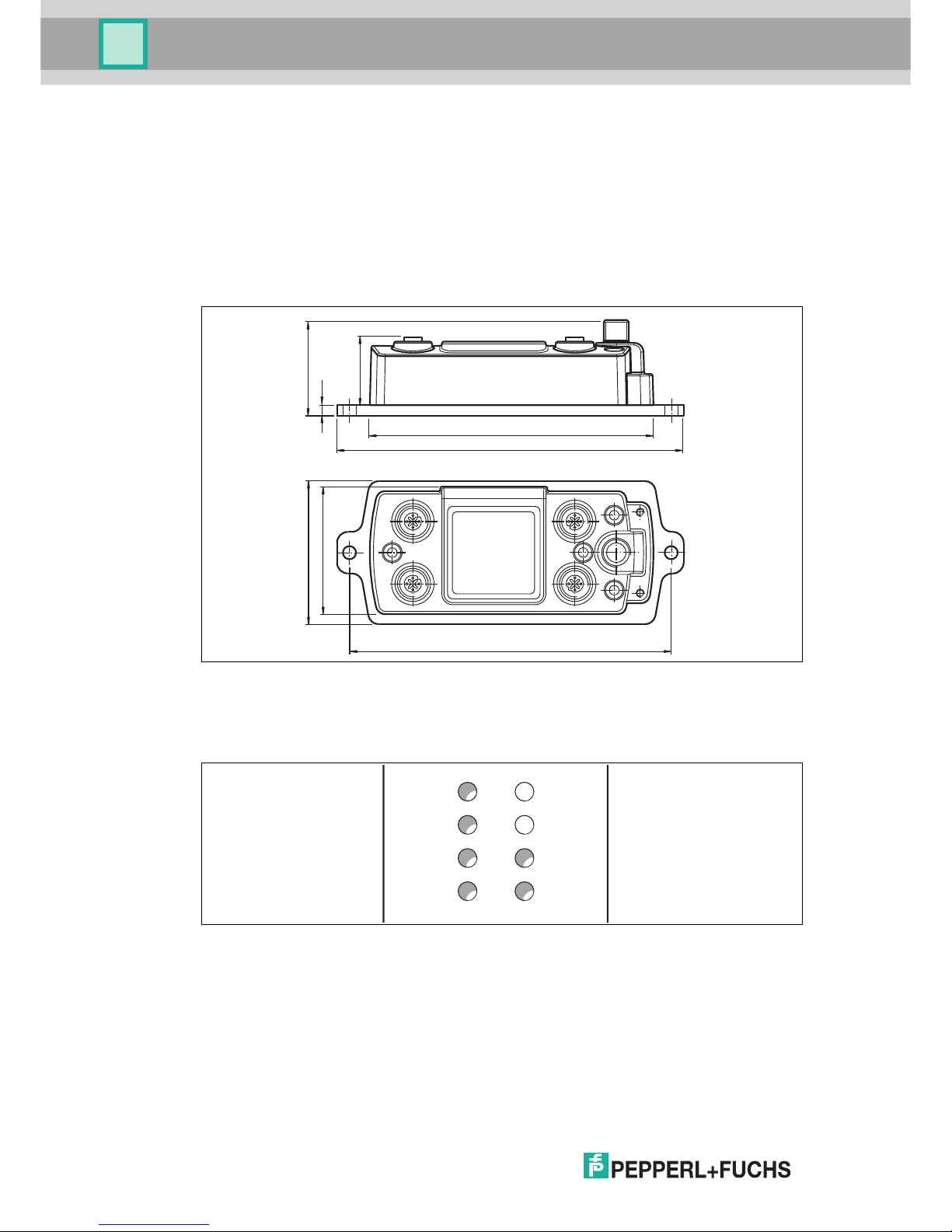
2.2 Dimensions
Figure 2.1
2.3 Indicators
The following indicators can be found on the OHV-F230-B17 gateway:
33
5
47
136.6
167
61.4
69
155
LEDs
PWR/ERR Green: gateway is switched on
Red: system error
BUS ERR Red: communication error with PROFINET network
Flashing red: configuration missing
ACTIVITY 1/ACTIVITY 2Yellow: data is being transferred to port 1 and port 2
LINK 1/LINK 2 Green: port 1 and port 2 are connected to the PROFINET network
PWR/ERR
BUS ERR
ACTIVITY 1
LINK 1
MOD STS
NET STS
ACTIVITY 2
LINK 2
Page 7

OHV-F230-B17
Product Specifications
2016-12
7
2.4 Interfaces
The following interfaces are available on the OHV-F230-B17 gateway:
Figure 2.2
2.5 Accessories
Handheld readers
Cordsets
Interface Description Connection
RS-232 RS-232, EIA/TIA-232E
Transfer rate: 115 k, 8N1
M12 socket, 8 pin, A-coded
RS-485 No function M12 socket, 8 pin, A-coded
PROFINET 2 x PROFINET IO with int. switch
Protocol: Conformance class B
Realtime class RT
Min. cycle time 1 ms
Transfer rate: 10/100 Mbit/s
M12 socket, 4 pin, D-coded
Main Power supply M12 socket, 4 pin, A-coded
2
3 1
4
3
4
2
1
1
7
4
2
6
3
5
8
Main
1 = + UB
2 = Teach In
3 = - UB/GND
4 = Trigger In
PROFINET 1 & 2
1
= Tx+
2 =
R
x+
3 = Tx4 = R
x-
RS232
1 = TX
2 = n.c.
3 = CTS
4 = RX
5 = RTS
6 = Trigger Out: 5 V; I
max
= 100 mA
7 = GND
8
=
5 V; I
max
=
500 mA
RS485
1 = Trigger Out: 24 V; I
max
= 200 mA
2 = + UB: I
max
= 1 A
3 = DATA +
4 = DATA 5 = Teach Out: 24 V; I
max
= 200 mA
6 = n.c.
7 = GND
8
=
5 V; I
max
=
500 mA
RS232
RS485
Designation Description
OHV100-F222-R2 Handheld reader for all common 1-D and 2-D codes
OHV1000-F223-R2 Handheld reader for reading lasered, punched, or printed 1-D and 2-D
codes
Designation Description
V19S-G-1.7/3M-PVC-V50 Cordset for handheld reader/gateway
V1SD-G-*M-PUR-ABG-V1SD-G
V1SD-G-*M-PUR-ABG-V45-G
PROFINET cordset; various lengths available
V1-* M12, A-coded, 4-pin, connects the gateway to the power
supply
You can find a wide range of compatible connection cables
at http://www.pepperl-fuchs.com.
Page 8

2016-12
8
OHV-F230-B17
Commissioning
3 Commissioning
Connecting the gateway to the handheld reader
1. Connect the OHV1000-F223-R2 and OHV100-F222-R2 handheld readers to the gateway
using the V19S-G-1.7/3M-PVC-V50 connection cable.
2. Connect the gateway to the power supply.
3. Scan the control code below using the handheld reader.
The handheld reader is connected to the gateway.
Page 9

OHV-F230-B17
Operation and Communication
2016-12
9
4 Operation and Communication
4.1 Communication via PROFINET
4.1.1 General Information on Communication via PROFINET
PROFINET is an open standard for industrial automation based on industrial Ethernet.
PROFINET integrates information technology with established standards such as TCP/IP and
XML in automation technology.
The communication concept for setting up decentralized applications within PROFINET is
PROFINET IO, i.e. decentralized field devices are integrated by PROFINET IO. The familiar IO
view of PROFIBUS DP is used where the usable data of the field devices is transferred to the
controller process image in cycles. PROFINET IO is a device model consisting of slots and
channels, which is based on the main features of PROFIBUS DP. The field device properties
are written in a GSDML (generic station description markup language) based on XML.
PROFINET IO is engineered in the same way as has long been the case for system integrators
of PROFIBUS DP. The decentralized field devices are assigned in the design of a controller.
PROFINET IO draws a distinction between three device types: IO controller, IO device, and IO
supervisor.
IO controller: Controller that executes the automation program.
IO device: Decentrally assigned field device that is assigned to an IO controller.
IO supervisor: Programming unit/PC with commissioning and diagnostic functions.
4.1.2 PROFINET IO Interface
OHV-F230-B17 gateways are PROFINET IO devices that communicate cyclically with the
assigned PROFINET IO controller during operation.
The PROFINET interface of the OHV-F230-B17 gateway supports:
■
A transfer rate of 100 Mbit/s
■
The real-time category RT
■
The range of functions in accordance with Conformance Class B
■
The identification and maintenance functions (I&M) IM0 – IM4
Identification & Maintenance Data
Identification and maintenance data (I&M data) is information stored in a device. I&M data
uniquely identifies a device within a system. The identification data (I data) includes information
about the device, for example the item number and device name. Identification data cannot be
changed.
Maintenance data (M data) includes information regarding the device within the system, for
example the installation location and installation date. Maintenance data is initially stored in the
device during installation; this data can be changed.
Data Input
The Step7 software from Siemens can be used to display and change the I&M data. You can
read and write I&M data 1, 2 and 3 in the "Target System" menu of the HW Config hardware
configuration using the functions "Download Module Identification" and "Download Module
Identification to PG". see Figure 4.1 on page 10.
Page 10

2016-12
10
OHV-F230-B17
Operation and Communication
I&M Data
Figure 4.1
4.1.3 Project Planning Using Device Description
As with PROFIBUS DP, a field device is integrated into the project planning tool by way of a
device description. The field device properties are described in the GSD file. The GSD file
contains the field device data (technical features and information for communication) that you
need to operate the device in a PROFINET network.
Import the GSD file into a project planning tool. Peripheral addresses are assigned to the
individual channels of the field devices. The peripheral input addresses incorporate the
received data. The user program evaluates and processes this data. The user program
generates the peripheral output values and sends them to the control interface.
Once project planning is complete, the IO controller receives the planning and configuration
data. The IO controller parameterizes and configures the field devices automatically.
I&M data 1 = system ID
location ID
I&M data 2 = installation date
I&M data 3 = additional
information
Page 11

OHV-F230-B17
Operation and Communication
2016-12
11
Downloading the GSD File
You can find the relevant GSD file in the Software section of the product detail page for the
device.
To access the product detail page for the device, go to http://www.pepperl-fuchs.com and type
information about the device (e.g., the product description or the item number) into the search
function.
Inserting the function block and data module
1. Unzip the zip file.
2. In the module folder, mark the OHV-F230-B17 function block and the associated iDB_OHV-
F230-B17 instance data block. Right-click on the marked entries and select Copy.
3. Right-click the destination project and select Insert.
Connecting the gateway to the S7 control panel
1. Before installing a GSD file, close all hardware configuration projects.
2. To install the GSD file, select Options > Install GSD files in the hardware configuration.
3. Connect the gateway to the PROFINET network.
4. To integrate the gateway into your PROFINET, double-click the PN-IO unit in the rack.
Figure 4.2 Assigned rack
This opens the Properties window.
5. Click Properties.
6. To create a new Ethernet subnet, click New.
7. To insert the Ethernet subnet into the hardware configuration, right-click the PN-IO unit and
select Insert PROFINET IO system.
Page 12

2016-12
12
OHV-F230-B17
Operation and Communication
Figure 4.3 Inserting PROFINET-IO system
A PROFINET IO system is now available to which you can connect new nodes.
8. Drag the PROFINET module of the gateway from the catalog into the connection window
and link it to the PROFINET IO system.
Figure 4.4 Assigned rack
Page 13

OHV-F230-B17
Operation and Communication
2016-12
13
9. To assign the gateway to the PROFINET module just inserted, select Destination system
> Ethernet > Edit Ethernet node from the menu bar. In the window that opens, click
Browse.
A list opens containing all accessible nodes.
Figure 4.5 Browsing PROFINET
10.Click OK.
11.Activate the Use IP parameters option in the Edit Ethernet node window.
Page 14

2016-12
14
OHV-F230-B17
Operation and Communication
Figure 4.6 Editing Ethernet nodes
12.If the device name of the node from the list open previously is present in the section Assign
device name (in this example ohv-f230), click Assign name.
13.Click Close.
14.Double-click the PROFINET module in the connection window and check whether the
device name has been successfully transferred. If the device name has not been
transferred, enter the device name in the field Device name.
Page 15

OHV-F230-B17
Operation and Communication
2016-12
15
Figure 4.7 PROFINET module properties
15.Click OK.
16.To assign address areas for inputs and outputs, add the following modules from the catalog
to the device:
- Result counter
- Result 64 byte
Figure 4.8 PROFINET configuration tables
Page 16

2016-12
16
OHV-F230-B17
Operation and Communication
4.1.4 PROFINET Address and Identifying a Device
Every PROFINET IO device has a unique device identification. This device identification
consists of the following:
■
A unique MAC address. This MAC address is printed on the back of the device.
■
A device name. The default device name is OHV-F230.
■
An IP address. The default IP address is 192.168.2.2.
4.1.5 PROFINET Modules
1 word = 16 bit value
1 byte = 8 bit value
Modules with response telegram
The following modules enable gateway data to be retrieved using PROFINET.
Result counter 32 bit module
The result counter increments a 32 bit value when a handheld reader has sent a result to the
gateway.
Result 64 byte module
Result message from the handheld reader
Size Type Content
2 words,
consistent
Input data 32 bit scan data
MSB first
MSB = most significant byte
Status byte 0 Status byte
Status byte 1 Message length
Data byte 0 Start of the scan result
MSB first
1
1.Example:
If the read code has a value of 123, the following data bytes are sent:
Data byte 0 = '1' (0x31)
Data byte 1 = '2' (0x32)
Data byte 2 = '3' (0x33)
All other data bytes: 0 (0x0)
Data byte 1 Scan result
... Scan result
Data byte 61 End of the scan result
Page 17

OHV-F230-B17
Operation and Communication
2016-12
17
Result 128 byte module
Result message from the handheld reader
Explanation of status bytes
Status byte 0 Status byte
Status byte 1 Message length
Data byte 0 Start of the scan result
MSB first
1
1.Example:
If the read code has a value of 123, the following data bytes are sent:
Data byte 0 = '1' (0x31)
Data byte 1 = '2' (0x32)
Data byte 2 = '3' (0x33)
All other data bytes: 0 (0x0)
Data byte 1 Scan result
... Scan result
Data byte 125 End of the scan result
Byte Content Bit no.
7 6 5 4 3 2 1 0
Status
byte 0
Status byte
ND
1
1.New data flag. Changes when the gateway receives new data from the scanner and makes it available for fieldbus
transmission. Is used to recognize new data with the same value.
0
DL
2
2.Data loss flag. Flag is set to 1 if the length of the scanned code exceeds the maximum number of data bytes in the
selected module. Is also set to 1 if a transmission error between the scanner and the gateway is detected.
0 0 0 0 0
Status
byte 1
Message length
Unsigned 8 bit
Number of usable
data bytes after the
status bytes
LEN_7 LEN_6 LEN_5 LEN_4 LEN_3 LEN_2 LEN_1 LEN_0
Page 18

2016-12
18
OHV-F230-B17
Appendix
5 Appendix
5.1 ASCII table
hex dec ASCII hex dec ASCII hex dec ASCII hex dec ASCII
00 0 NUL 20 32 Space 40 64 @ 60 96 '
01 1 SOH 21 33 ! 41 65 A 61 97 a
02 2 STX 22 34 " 42 66 B 62 98 b
03 3 ETX 23 35 # 43 67 C 63 99 c
04 4 EOT 24 36 $ 44 68 D 64 100 d
05 5 ENQ 25 37 % 45 69 E 65 101 e
06 6 ACK 26 38 & 46 70 F 66 102 f
07 7 BEL 27 39 ' 47 71 G 67 103 g
08 8 BS 28 40 ( 48 72 H 68 104 h
09 9 HT 29 41 ) 49 73 I 69 105 I
0A 10 LF 2A 42 * 4A 74 J 6A 106 j
0B 11 VT 2B 43 + 4B 75 K 6B 107 k
0C 12 FF 2C 44 , 4C 76 L 6C 108 l
0D 13 CR 2D 45 - 4D 77 M 6D 109 m
0E 14 SO 2E 46 . 4E 78 N 6E 110 n
0F 15 SI 2F 47 / 4F 79 O 6F 111 o
10 16 DLE 30 48 0 50 80 P 70 112 p
11 17 DC1 31 49 1 51 81 Q 71 113 q
12 18 DC2 32 50 2 52 82 R 72 114 r
13 19 DC3 33 51 3 53 83 S 73 115 s
14 20 DC4 34 52 4 54 84 T 74 116 t
15 21 NAK 35 53 5 55 85 U 75 117 u
16 22 SYN 36 54 6 56 86 V 76 118 v
17 23 ETB 37 55 7 57 87 W 77 119 w
18 24 CAN 38 56 8 58 88 X 78 120 x
19 25 EM 39 57 9 59 89 Y 79 121 y
1A 26 SUB 3A 58 : 5A 90 Z 7A 122 z
1B 27 ESC 3B 59 ; 5B 91 [ 7B 123 {
1C 28 FS 3C 60 < 5C 92 \ 7C 124 |
1D 29 GS 3D 61 = 5D 93 ] 7D 125 }
1E 30 RS 3E 62 > 5E 94 ^ 7E 126 ~
1F 31 US 3F 63 ? 5F 95 _ 7F 127 DEL
Page 19

Sub ject to modificatio ns
Cop yright PEPPERL+FUCHS • Printed in Germa ny
www.pepperl-fuchs.com
FACTORY AUTOMATION –
SENSING YOUR NEEDS
Worldwide Headquarters
Pepperl+Fuchs GmbH
68307 Mannheim · Germany
Tel. +49 621 776-0
E-mail: info@de.pepperl-fuchs.com
USA Headquarters
Pepperl+Fuchs Inc.
Twinsburg, Ohio 44087 · USA
Tel. +1 330 4253555
E-mail: sales@us.pepperl-fuchs.com
Asia Pacific Headquarters
Pepperl+Fuchs Pte Ltd.
Company Registration No. 199003130E
Singapore 139942
Tel. +65 67799091
E-mail: sales@sg.pepperl-fuchs.com
/ DOCT-5408
12/2016
 Loading...