

Page 1

MANUAL
ODT-MAC400-* /
ODT-MAC401-* /
ODT-MAC403-*
FACTORY AUTOMATION
Stationary reader for all
common 1D- and 2D-barcodes
Laser Class 2M
EN 60825-1
Page 2

ODT-MAC400-* / ODT-MAC401-* / ODT-MAC403-*
With regard to the supply of products, the current issue of the following document is applicable: The
General Terms of Delivery for Products and Services of the Electrical Industry, published by the
Central Association of the Electrical Industry (Zentralverband Elektrotechnik und Elektroindustrie
(ZVEI) e.V.) in its most recent version as well as the supplementary clause: "Expanded reservation
of proprietorship"
Page 3

ODT-MAC400-* / ODT-MAC401-* / ODT-MAC403-*
Contents
1 Introduction......................................................................... 4
2 Declaration of conformity .................................................. 5
3 Safety................................................................................... 6
3.1 Symbols relevant to safety ............................................................................6
3.2 Intended use .................................................................................................6
3.3 General safety instructions ............................................................................6
4 Product Description ........................................................... 8
4.1 Use and application of the
ODT-MAC400-* / ODT-MAC401-* / ODT-MAC403-* -....................................8
4.2 Displays and controls....................................................................................8
4.3 Interfaces and connections ...........................................................................9
4.4 Contents .....................................................................................................10
4.5 Accessories ................................................................................................11
4.5.1 Cables....................................................................................................11
4.5.2 Other accessories ..................................................................................11
5 Installation......................................................................... 12
5.1 Preparation .................................................................................................12
5.2 Mounting.....................................................................................................12
5.3 Connecting the device ................................................................................13
5.4 Assigning an IP address to a network connection using Windows XP.........14
5.5 Storage and transport .................................................................................16
6 Commissioning................................................................. 17
6.1 Connecting the stationary reader ................................................................17
7 Operation........................................................................... 18
7.1 Web-based operator interface.....................................................................18
7.1.1 Settings Tab............................................................................................20
7.1.2 Communication Tab................................................................................50
7.1.3 Tab Gallery..............................................................................................51
7.1.4 Dialog box Language .............................................................................52
8 Troubleshooting................................................................ 53
8.1 What to do in the event of an error ..............................................................53
9 Appendix ........................................................................... 54
9.1 Command format ........................................................................................54
9.2 Command overview ....................................................................................56
9.3 Input of nonprintable characters..................................................................61
216677 2012-05
3
Page 4

ODT-MAC400-* / ODT-MAC401-* / ODT-MAC403-*
Introduction
1Introduction
Congratulations
You have chosen a device manufactured by Pepperl+Fuchs. Pepperl+Fuchs
develops, produces and distributes electronic sensors and interface modules for
the market of automation technology on a worldwide scale.
Symbols used
The following symbols are used in this manual:
Note!
This symbol draws your attention to important information.
Handling instructions
You will find handling instructions beside this symbol
Contact
If you have any questions about the device, its functions, or accessories, please
contact us at:
Pepperl+Fuchs GmbH
Lilienthalstraße 200
68307 Mannheim
Telephone: +49 621 776-4411
Fax: +49 621 776-274411
E-Mail: fa-info@pepperl-fuchs.com
216677 2012-05
4
Page 5

ODT-MAC400-* / ODT-MAC401-* / ODT-MAC403-*
Declaration of conformity
2 Declaration of conformity
This product was developed and manufactured under observance of the
applicable European standards and guidelines.
Note!
A Declaration of Conformity can be requested from the manufacturer.
The product manufacturer, Pepperl+Fuchs GmbH, D-68307 Mannheim, has a
certified quality assurance system that conforms to ISO 9001.
ISO9001
216677 2012-05
5
Page 6

ODT-MAC400-* / ODT-MAC401-* / ODT-MAC403-*
Safety
3Safety
3.1 Symbols relevant to safety
Danger!
This symbol indicates a warning about an immediate possible danger.
In case of ignoring the consequences may range from personal injury to death.
Warnin g!
This symbol indicates a warning about a possible fault or danger.
In case of ignoring the consequences may cause personal injury or heaviest
property damage.
Caution!
This symbol indicates a warning about a possible fault.
In case of ignoring the devices and any connected facilities or systems may be
interrupted or fail completely.
3.2 Intended use
The ODT-MAC4**-LD-RD-MC stationary reader is intended to be used only for the
identification of objects by means of 1D- and 2D-codes.
Always operate the device as described in these instructions to ensure that the
device and connected systems function correctly. The protection of operating
personnel and plant is only guaranteed if the device is operated in accordance
with its intended use.
3.3 General safety instructions
Class 2 laser product
This device is a class 2 laser product:
Standard s
IEC 60825-1:2007 certified. Complies with 21 CFR 1040.10 and 1040.11 except
for deviations pursuant to Laser Notice No. 50, dated 06-24-07.
216677 2012-05
6
Page 7

ODT-MAC400-* / ODT-MAC401-* / ODT-MAC403-*
Safety
Warn ing !
Visible red class 2 laser light
The irradiation can lead to irritation especially in a dark environment. Do not point
at people!
Caution: Do not look into the beam!
Maintenance and repairs should only be carried out by authorized service
personnel!
Attach the device so that the warning is clearly visible and readable.
Caution – Use of controls or adjustments or performance of procedures other
than those specified herein may result in hazardous radiation exposure..
Only use recommended original accessories.
The operating company bears responsibility for observing locally applicable
safety regulations.
Installation and commissioning of all devices must be performed by a trained
professional only.
User modification and or repair are dangerous and will void the warranty and
exclude the manufacturer from any liability. If serious faults occur, stop using the
device. Secure the device against inadvertent operation. In the event of repairs,
return the device to your local Pepperl+Fuchs representative or sales office.
216677 2012-05
7
Page 8
ODT-MAC400-* / ODT-MAC401-* / ODT-MAC403-*
1
3
2
Product Description
4 Product Description
4.1 Use and application of the ODT-MAC400-* / ODT-MAC401-* / ODT-MAC403-* -
The stationary reader is an optical identification system for detection of up to 28
different code symbologies. With its high-performance signal processor, a partial
image capture function, and optimized decoding algorithms, the device features
extremely high reading speeds.
The stationary reading device can be configured easily and quickly using a
normal web browser, via the standard Ethernet interface or a series connection.
Support is also provided for the mechanical alignment of the reading device in the
form of an integrated laser pointer and a connected VGA monitor. The reading
device also features an integrated error image memory.
Typical areas of application are
■ Document handling
■ Printing machines
■ Identification in the packaging and warehouse sector
■ PCB identification
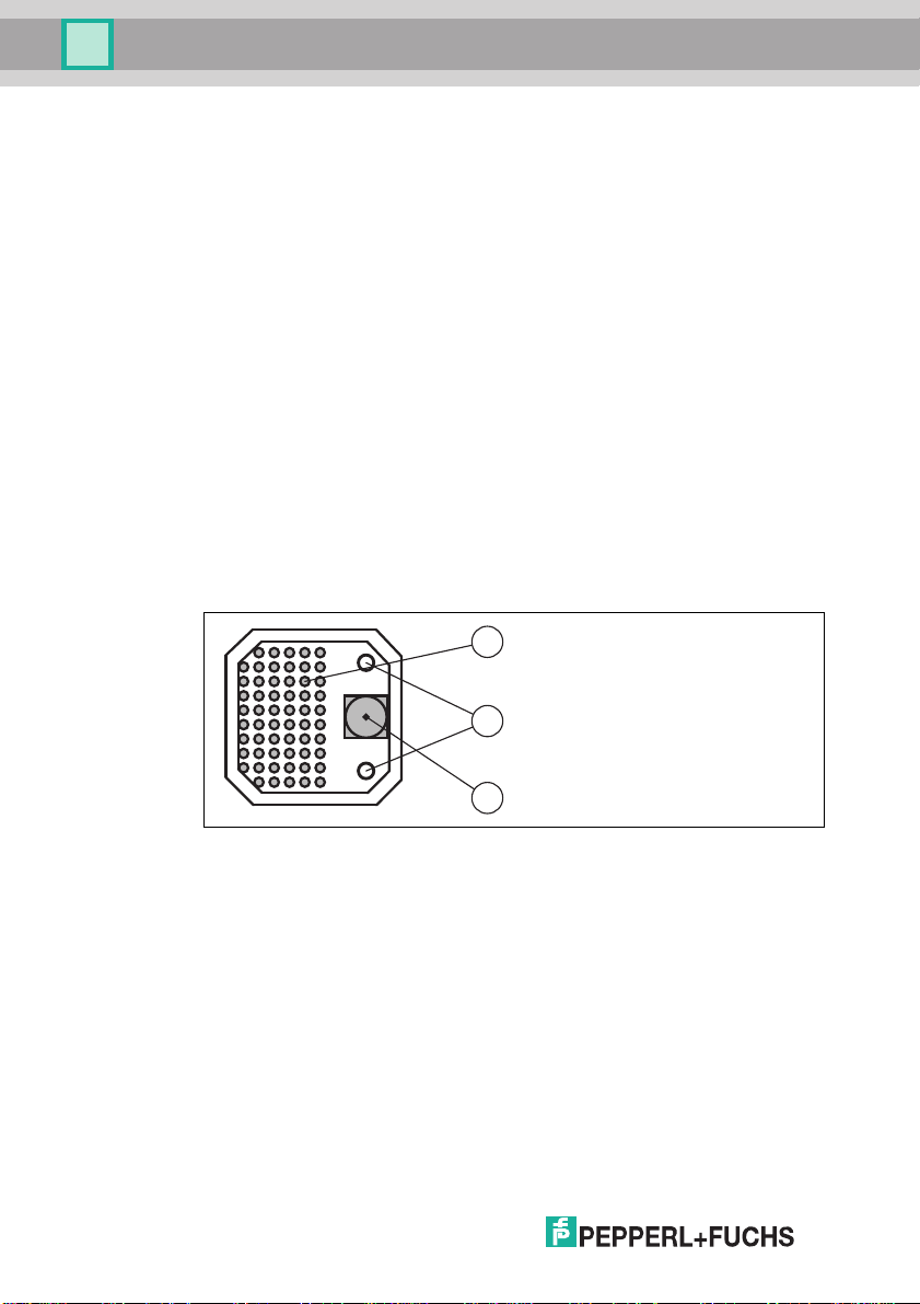
4.2 Displays and controls
1. Lightning unit
2. Laser diodes
3. CMOS camera
The stationary reader ODT-MAC403-* does not have laser diodes.
216677 2012-05
8
Page 9
ODT-MAC400-* / ODT-MAC401-* / ODT-MAC403-*
4
1
2
3
LAN
TCP/IP
ST
VGA
VCC/I-O/RS232
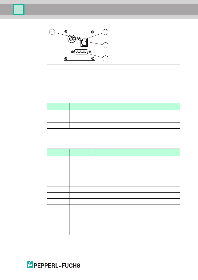
Product Description
1 RJ45 Ethernet network socket
2 Video output VGA 640x480
3 15 pin D-Sub connector
4 Status LED
Stat us LE D
LED color Description
Ye l l o w The LED turns to yellow for a short time after switching on.
Green The LED flashes green after a successful read (good read).
Red The LED flashes red after an unsuccessful read (bad read).
4.3 Interfaces and connections
15-pin D-sub connector
PIN Signal Description
1, 2 GND GND for device
3 IO GND GND for inputs/ outputs
4, 5 +24 V Supply for device, 24 V DC PELV ±15%
6 IO +24 V Supply for inputs/ outputs, 24 V DC PELV ±15%
7 RTS Handshake signal, RS 232
8 IN1 24 V DC input
9 IO-OUT0 24 V DC "good read" output
10 IO-OUT1 24 V DC "bad read" output
11 IO-IN0 24 V DC "trigger" input
12 CTS Handshake signal, RS 232
13 TXD Transmission line, RS 232
14 RXD Receive line, RS 232
15 IN2 24 V DC input
216677 2012-05
9
Page 10
ODT-MAC400-* / ODT-MAC401-* / ODT-MAC403-*
3
4
5
6
7
8
1
2
Product Description
Video output VGA 640x480 (7-pin cylindrical connector)
PIN Signal Description
1 OUT V
2 GND RGB Red signal, green signal and blue signal ground
3 OUT R Red signal output
4 OUT G Green signal output
5 GND Horizontal synchronization output ground and vertical
6 OUT B Blue signal output
7 OUT H
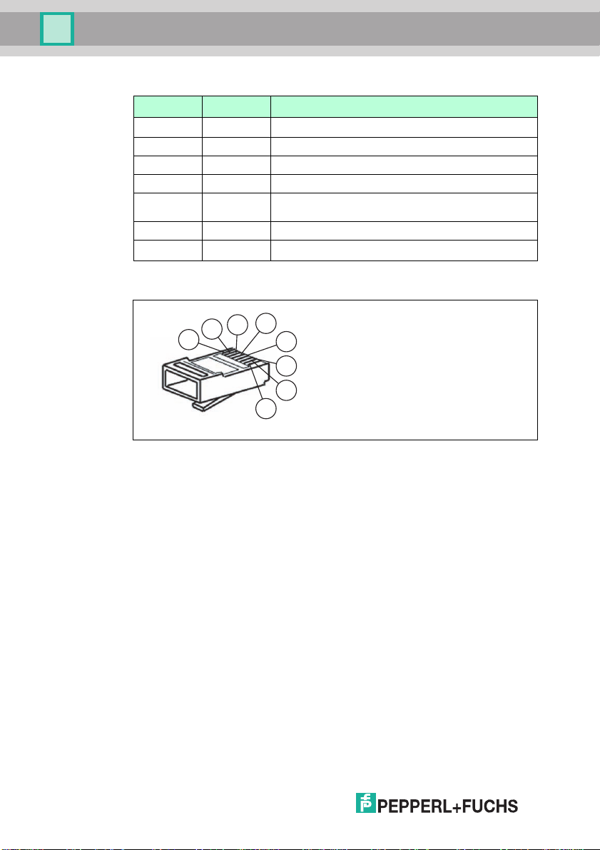
Network connection
Vertical synchronization output
sync
synchronization output ground
Horizontal synchronization output
sync
Figure 4.1 Network connection pin assignments
1 Transmit data (+)
2 Transmit data (-)
3 Receive data (+)
4 Not assigned
5 Not assigned
6 Receive data (-)
7 Not assigned
8 Not assigned
4.4 Contents
■ ODT-MAC4**-LD-RD-MC
■ Quick start guide
10
216677 2012-05
Page 11

ODT-MAC400-* / ODT-MAC401-* / ODT-MAC403-*
Product Description
4.5 Accessories
Various accessories are available.
4.5.1 Cables
The following cables are available as accessories.
Model number Description
ODZ-MAC-CAB-VIDEO Video connection cable, cylindrical connector, 7-pin on SUB-
ODZ-MAC-CAB15POL-2,5M-FEMALE
ODZ-MAC-CAB15POL-5M-FEMALE
ODZ-MAC-CAB-24VR2-2M
V45-G-10M-V45-G Network cable RJ45, category 5, up to 100 MHz, 10 m
4.5.2 Other accessories
Other products are available as accessories.
Model number Description
ODZ-MAC-PWR-24V Desk top power supply 24 V DC, 1.88 A
D socket, 15-pin VGA, 2 meters
Connection cable, Sub-D socket, 15-pin, 2.5 meters, can be
pre-assembled
Connection cable, Sub-D socket, 15-pin, 5 meters, can be
pre-assembled
Connection cable for power supply, RS 232
216677 2012-05
11
Page 12
ODT-MAC400-* / ODT-MAC401-* / ODT-MAC403-*
Reading distance
60
60
M5
20
Code
52.7
20 ±0.1
36.85
6.5
Reading distance
11
60
60 65
M5
20 6
11
Code
52.7
20 ±0.1
72.5
Installation
5 Installation
5.1 Preparation
Unpacking the unit
1. Check that all package contents are present and undamaged.
If anything is damaged, inform the shipper and contact the supplier.
2. Check that all items are present and correct based on your order and the
shipping documents.
If you have any questions, please contact Pepperl+Fuchs.
3. Keep the original packing material in case you need to store or ship the unit at
a later time.
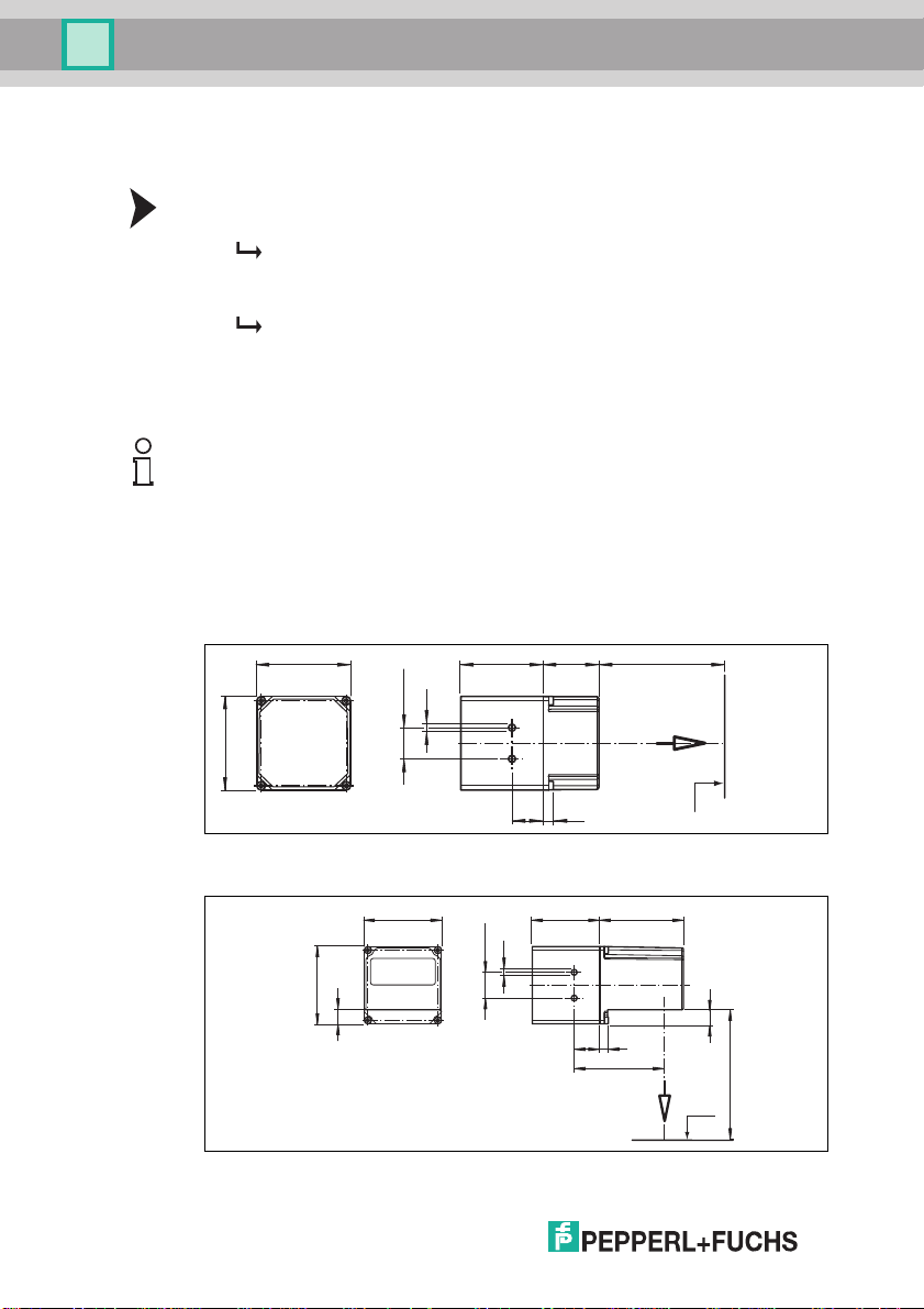
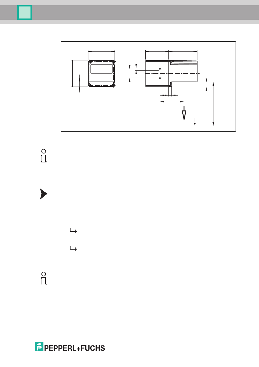
5.2 Mounting
Note!
Preventing reflection and glare
Reflection and glare from reflective surfaces can impair the captured image and
therefore lead to incorrect readings. To prevent reflection and glare, install the
stationary reading device at a slight angle.
Please refer to the technical data in the data sheet for the read distance.
ODT-MAC400-*
Figure 5.1 Dimensions of the straight housing
ODT-MAC401-*
12
Figure 5.2 Dimensions of the angle housing
216677 2012-05
Page 13
ODT-MAC400-* / ODT-MAC401-* / ODT-MAC403-*
Reading distance
11
60
60 65
M5
20 6
11
Code
52.7
20 ±0.1
54.5
Installation
ODT-MAC403-*
Figure 5.3 Dimensions of the angle housing
Note!
Connection to ground
When installing the device, ensure that it is has a ground connection.
5.3 Connecting the device
Connecting the power supply
To connect a power supply to the device, proceed as follows.
1. Plug the 15-pin Sub-D socket into the connector provided for this purpose on
the back of the housing.
2. Screw in the two mounting screws as far as possible.
This ensures that the cable cannot be inadvertently pulled out.
3. Next connect the power supply to the appropriate pins on the Sub-D socket.
The power supply has now been connected.
To connect the power supply to the device quicker, the pre-configured connection
cable can also be used. Information can be found in the Accessories section.
Note!
216677 2012-05
Record the network configuration
The device communicates with the connected machine control system using the
TCP/IP protocol. To ensure communication works correctly, you must note down
all the changes you make to the network configuration.
13
Page 14
ODT-MAC400-* / ODT-MAC401-* / ODT-MAC403-*
Installation
Note!
Network cabling
Use a crossover network cable to connect the device directly to a PC. If the device
is being operated within a network, use a twisted-pair network cable to connect it
to the network.
Establishing a network connection
In order to establish a network connection, proceed as follows.
When delivered, the device has a fixed IP address (192.168.2.2). To facilitate
communication within the network, you must configure your network. The
configuration data can be found in the network configuration overview.
Connecting a trigger sensor
To connect a trigger sensor, proceed as follows.
Connect the trigger sensor to the cable previously connected for the power
supply.
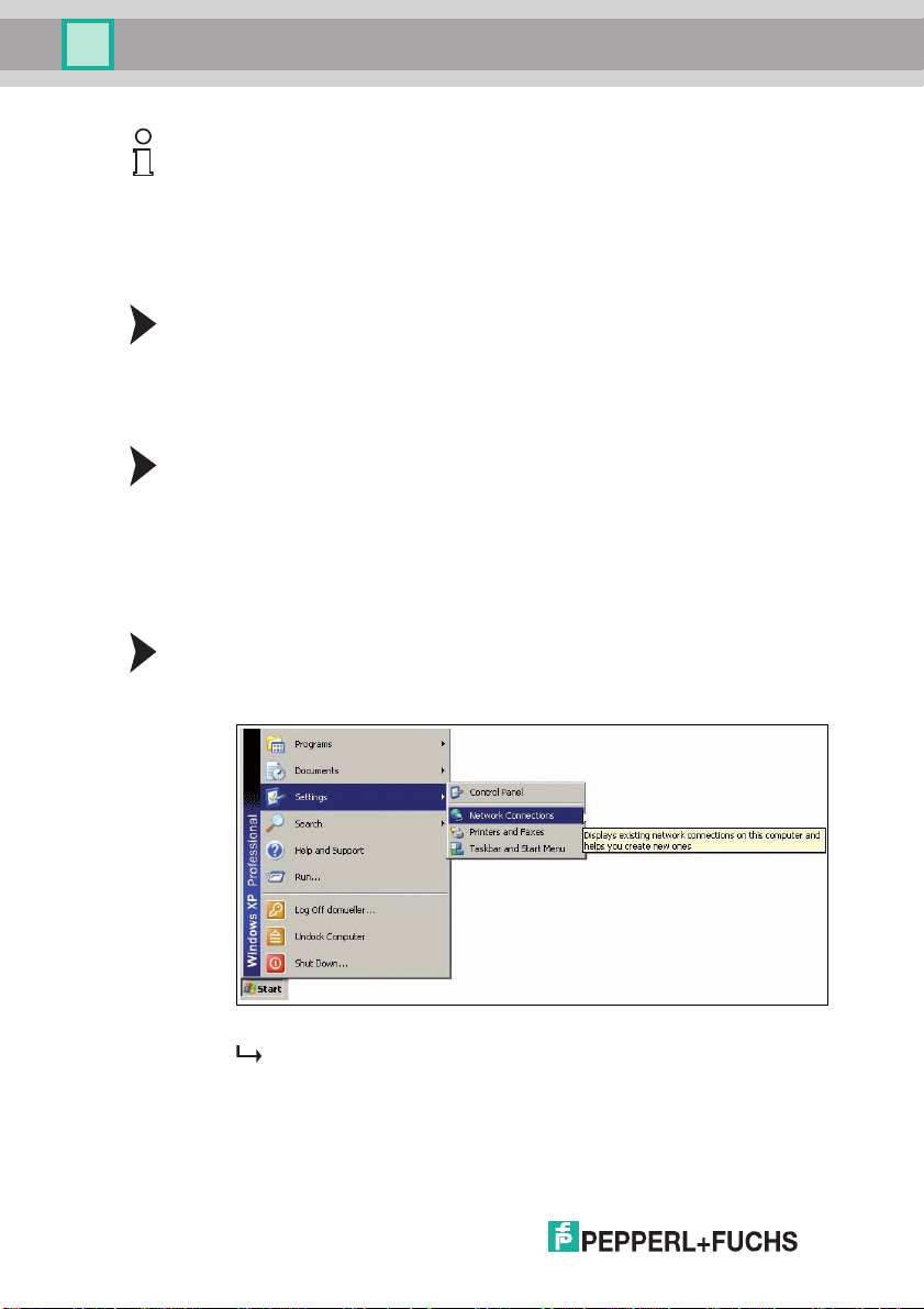
5.4 Assigning an IP address to a network connection using Windows XP
To assign an IP address to a network connection using Windows XP,
proceed as follows.
1. First select "Network Connections".
14
2. Then open the required connection by double clicking on it.
The Properties dialog box for the relevant connection will open.
216677 2012-05
Page 15
ODT-MAC400-* / ODT-MAC401-* / ODT-MAC403-*
Installation
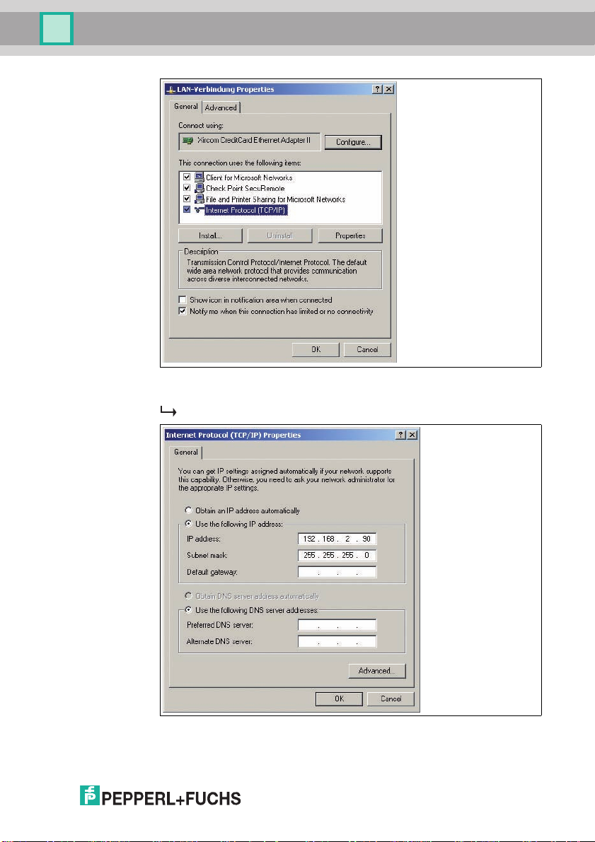
3. Select the "Internet Protocol (TCP/IP)" element from the Properties dialog
box by double clicking on it.
The TCP/IP properties dialog box will open.
4. In the TCP/IP properties dialog box, activate "Use the following IP
address".
216677 2012-05
15
Page 16

ODT-MAC400-* / ODT-MAC401-* / ODT-MAC403-*
Installation
5. Enter an IP address which only differs from the sensor IP address in the very
last segment.
6. Enter 255.255.255.0 as the subnet mask.
7. Then confirm your entries on the TCP/IP properties page and the LAN
connection properties page using "OK" and "Close".
This completes the network configuration and the sensor can be used.
5.5 Storage and transport
For storage and transport purposes, package the unit using shockproof
packaging material and protect it against moisture. The best method of protection
is to package the unit using the original packaging. Furthermore, ensure that the
ambient conditions are within allowable range.
16
216677 2012-05
Page 17

ODT-MAC400-* / ODT-MAC401-* / ODT-MAC403-*
Commissioning
6 Commissioning
6.1 Connecting the stationary reader
The reader has its own web server. You have the option of making settings on the
stationary reader using a standard web browser.
Aligning the stationary reader
To find the ideal alignment for the device, use the two laser diodes in the
stationary reader.
1. Supply power to the reader via the D-Sub connector.
2. Adjust the stationary reader so that both points generated by the laser diodes
are positioned on top of each other on the code to be read.
This sets the ideal reading distance between the stationary reader and the
code to be read.
216677 2012-05
17
Page 18
ODT-MAC400-* / ODT-MAC401-* / ODT-MAC403-*
Operation
7Operation
7.1 Web-based operator interface
You have the option of configuring and operating the sensor via a web-based
operator interface and using it to display information. The web-based user
interface should be used only for setup and troubleshooting purposes when the
machine is shut down.
Note!
To start the operator interface of the sensor, you need a standard web browser
(e.g., Windows Internet Explorer or Mozilla Firefox) with Java script activated.
We recommend the following browser versions
Firefox 3.6.8 or higher Communication between MAC and
Internet
Explorer
Starting the operator interface
To start the operator interface, proceed as follows.
In the input field of a standard web browser, enter the IP address of the stationary
reader (192.168.2.2) and press return to confirm.
6.0.2900.2180 or higher Communication between MAC and
PC via LAN interface
PC via LAN interface
18
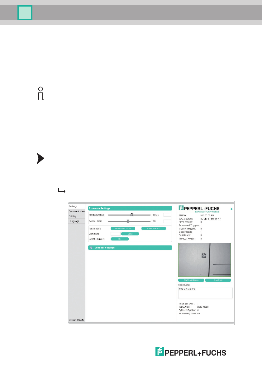
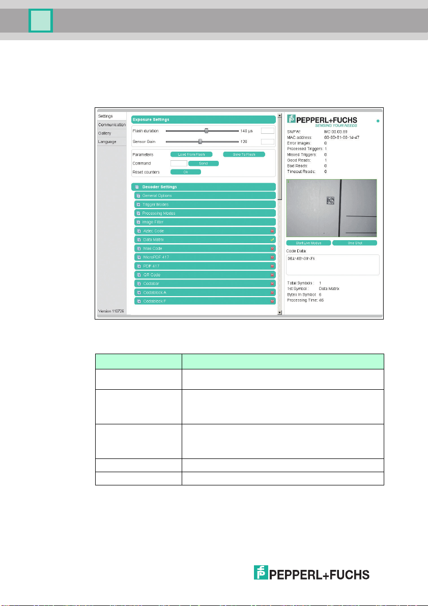
The following tab opens as the start page: Settings.
216677 2012-05
Page 19

ODT-MAC400-* / ODT-MAC401-* / ODT-MAC403-*
Operation
The following four tabs can be found on the left-hand side of the display:
■ Settings
■ Communication
■ Gallery
■ Language
Various information is displayed in the central section–depending on which tab is
active.
On the right-hand side, various status information (such as the software/firmware
version, the MAC address, the number of reads, etc.) is displayed, as well as the
last image captured and the decoded information. On the right of the
Pepperl+Fuchs company logo there is a pictorial representation of a status LED.
This status LED lights up green when a device is connected. Otherwise it is red.
Activating live image capture
Note!
By viewing the captured images on the operator interface during operation, the
image refresh rate reduces significantly.
To activate live image capture, click the Star t Liv e Modebutton on the right-hand
side of the display screen.
The stationary reader starts to capture images. The captured images are
displayed in the results window. The decoded information is displayed beneath it
in a separate window.
Starting single image capture
On the right-hand side of the display screen, click on the button Single image.
Clicking the button triggers a single image capture.
216677 2012-05
19
Page 20
ODT-MAC400-* / ODT-MAC401-* / ODT-MAC403-*
Operation
7.1.1 Settings Ta b
The Settings tab enables you to configure various parameters and send
commands to the sensor. In the left display area, you can navigate to the other
tabs Communication, Gallery and Language.
20
In the center of the screen, the following functions are available in different fields:
Sensor parameters
Settings Explanation
Flash duration This parameter is used to set the duration of the flash at
Ga i n This parameter is used to set the electronic brightness gain. A
Parameter set Load from Flash: Use this button to load parameter settings
Command Send individual commands to the sensor.
Reset counter The trigger counter value can be reset to 0 here.
intervals of 10 µs.
high value electronically increases the brightness of the
captured image and can improve the readability of the code
considerably in the event of poor ambient conditions.
from the internal memory (Flash EEPROM).
Save to Flash: Use this button to save your current parameter
settings in the internal memory (Flash EEPROM).
216677 2012-05
Page 21

ODT-MAC400-* / ODT-MAC401-* / ODT-MAC403-*
Operation
Sending a command
You have the option of sending individual commands to the sensor. The
commands are made up of 4-digit hexadecimal numbers (0 ... 9, A ... F). An
overview of the available commands can be found in the appendix.
1. If you are not already on the Settings tab, navigate to it.
2. Enter a valid, 4-digit hexadecimal number for the required command in the
Command field.
3. Click on Send.
The relevant command will be sent to the sensor, where it will be
executed.
Decoder parameters
Settings can be applied to the individual symbologies via the “Decoder
parameters” menu option. The green checkmark and red cross show which
symbologies have been activated and which have not. They can be activated or
deactivated via the respective menus. You can configure settings to the general
operating principle of the sensor via the Gen era l s e t ti ngs menu option.
General settings
■ Any new values entered in a text box are sent to the reader automatically
after approximately 1.5 seconds. Pressing the enter key is not absolutely
required.
■ If an invalid character is entered in a text box (e.g., a letter in a numerical
field), the background is highlighted red and the value is not sent to the
reader. If a value outside the validity range is entered, the background is
also highlighted red.
The general settings for operation are entered here.
■ Trigger signal edge: Configures the inputs for rising edge or falling edge
■ Triggers for edge/level (individual triggers only): Configures the inputs
for edge and level sensitivity
■ Decoder mode: Configuration option of automatic or assisted. If the
option automatic is selected, no defined distances between the reader
and the code are adopted. If the option assisted is selected, a fixed read
distance between the reader and code carrier is adopted (refer to the
technical data in the data sheet for the read distance). This defines the size
of the code. However, additional settings are required as a result (reading
window width).
■ Contrast improvements: The following options can be used to increase
the detection reliability of codes and images with low levels of contrast.
Either general linear codes (apart from Interleaved 2/5), just Interleaved
2/5, or both can be activated. Activating these options can result in longer
decoding times and must be assessed on a case-by-case basis.
■ Average reading window width (mm): The value range is 10 mm ... 200
mm. Input of the average reading window width.
216677 2012-05
21
Page 22

ODT-MAC400-* / ODT-MAC401-* / ODT-MAC403-*
Operation
■ Image mode: How the code is to be read. If mirrored is selected, then the
reader expects a mirrored code (read via a deviation mirror).
■ Select parameter file: A backup file can be loaded into the sensor. Use
the Browse...button to select the file and then load it into the sensor with
the Send button.
■ Download parameter file: The settings that you have made can be saved
in a backup file.
■ Set default decoder parameters: Resets all values to their default values.
Explanation of trigger signal edge and triggers for edge/level:
Trigger signal edge: The sensor responds to edges, i.e., signal changes
(rising/falling edge) that are triggered by a photoelectric sensor.
Trigger rising edge
Trigger
Decoder
Result
Figure 7.1 Pulse diagram trigger rising edge
22
Triggers for edge/level: The sensor responds to a pending level, which means it
initiates synchronous trigger cycles as long as the signal is pending, i.e., image
capture, decoding, image capture, decoding, image capture, decoding.
Automatic sensor start
If “Trigge rs fo r edge/ le v el” mode is activated, it is possible for the sensor to start
running automatically and trigger, if the trigger input wiring is connected
permanently to High (or Low).
Procedure: Triggers for level active and single trigger mode active -> Trigger as
long as level is High.
216677 2012-05
Page 23

ODT-MAC400-* / ODT-MAC401-* / ODT-MAC403-*
Trigger
Decoder
Result
Trigger
Trigger rising edge
Operation
Figure 7.2 Pulse diagram trigger rising edge and level
Figure 7.3 Decoder settings - General Options
216677 2012-05
23
Page 24

ODT-MAC400-* / ODT-MAC401-* / ODT-MAC403-*
Operation
Trigger modes
Under the Trigger modes menu item, you can select whether to process one or
several triggers and specify how these triggers should be processed.
Trigger modes: Single trigger
In Single trigger mode, one image is captured and decoded for each external
trigger. Any other triggers that arise during the decoding process are ignored.
Activating the function Permit asynchronous triggers permits triggers during
decoding.
■ Suppress unsuccessful read (RS232 & TCP/IP): Specifies whether the
output of the signal or output string from an unsuccessful read should be
suppressed (activated) or not suppressed (deactivated).
■ Machine cycle: Machine cycle setting. The value must be greater than
20 ms. The value specifies the time gap between each incoming external
trigger (minimum time). The setting has an effect on the timeout.
■ Permit asynchronous triggers: Specifies whether or not asynchronous
triggers are permitted. If the field is activated, another trigger can be
processed while a captured image is being processed.
machine cycle
Trigger
Picture
recording
mc
24
Decoder
Result
Figure 7.4 Pulse diagram single trigger
216677 2012-05
Page 25

ODT-MAC400-* / ODT-MAC401-* / ODT-MAC403-*
Operation
Trigger modes: Interval burst trigger
In Interval burst trigger mode, several images are captured and decoded for each
external trigger. An interval is defined, during which several images are captured.
The burst length and time limit define the minimum number of images or decoding
attempts: Number N = burst length / (20 ms + time limit). Any other triggers that
arise during the burst are ignored and counted as missed triggers.
■ Suppress unsuccessful read (RS232 & TCP/IP): Specifies whether the
output of the signal or output string from an unsuccessful read should be
suppressed (activated) or not suppressed (deactivated).
■ Burst length: Burst length setting in ms. The value range is 0 ms ... 30000
ms. Entering the number 30001 is the equivalent of setting no limit, i.e.,
once the reader starts triggering, it carries on continuously. Continuous
burst mode can be terminated by a command (8400) or pulse at the second
input.
■ Decoder timeout: Specifies the decoder timeout, between 10 ms and
10000 ms. Here, enter the maximum time that the decoder should attempt
to decode a captured image.
■ Stop after good reading: Specifies whether the burst is stopped after a
good reading. If the burst length is set to infinite, the burst does not stop
after a good reading.
■ Duplicate suppression (ms): The value range is 0 ms ... 30000 ms. Here,
enter the maximum time that the last decoding result should be ignored.
Example: A code is ignored if it cannot be retrieved quickly enough from the
read area and the same code is read again.
■ Gain hysteresis: Activate or deactivate the gain hysteresis. The gain value
hysteresis may be useful if the contrast of symbols scheduled for scanning
is varied. The hysteresis can be deactivated or activated with ± 1 increment
up to an increment quantity of ± 15 increments . When an increment width
of 2 is entered, a total of 5 captures are triggered.
Example: The gain is set to 100, the gain hysteresis is activated with 2
increments, and the increment width is set to 5, which means that when a
trigger occurs, 5 images with the following gain values are captured in
succession: 100, 105, 95, 110, 90. The preset gain value is the average
value of the hysteresis, so to speak. (Note: The gain value range extends
from 0 to 255. If the upper or lower limit is exceeded as a result of the
hysteresis process, the relevant gain value is limited to 0 or 255. Example:
Gain 50, 4 increments, increment width 20, -> gain values: 50, 70, 30, 90,
10, 110, 0, 130, 0). The gain hysteresis stops if decoding is successful.
216677 2012-05
25
Page 26

ODT-MAC400-* / ODT-MAC401-* / ODT-MAC403-*
Trigger
Picture
recording
Decoder
Result
Burst length
Operation
Figure 7.5 Pulse diagram burst trigger interval
216677 2012-05
26
Page 27

ODT-MAC400-* / ODT-MAC401-* / ODT-MAC403-*
Trigger
Picture
recording
Decoder
Result
Interval
Operation
Trigger modes: Frame burst trigger
In Frame burst trigger mode, several images are captured and decoded for each
external trigger. The maximum number of images and the time between each
image captured in a burst is defined. Any other triggers that arise during the burst
are ignored and counted as missed triggers. The frame burst trigger stops if
decoding is successful.
■ Number of images per burst: Specifies the maximum number of images
captured in each burst. Option of selecting between 2 and 9.
■ Interval between frames: Specifies the length of the intervals between
the frames. Option of selecting between 20 ms and 30000 ms.
■ Decoder timeout: Entry specifying the decoder timeout. Option of
selecting between 10 ms and 10000 ms. Here, enter the maximum time
that the decoder should attempt to decode a captured image.
Figure 7.6 Pulse diagram burst trigger frame
216677 2012-05
27
Page 28

ODT-MAC400-* / ODT-MAC401-* / ODT-MAC403-*
Operation
Processing modes
Under Processing mode, you can specify whether an image should contain one or
several symbols and whether these symbols should be imported. If several
symbols are scheduled to be read, you will need to specify how the individual
results will be used to compile the output string.
Processing mode: Single window
In Single window mode, you can search for and decode 1 symbol in 1 active
window. The size and position of the window can be selected as required. Only
the window area is processed to enable quicker decoding.
■ Reference code/match code: The reference code/match code function
can be used only in Single window processing mode.
■ Comparison code: The comparison code is entered here. When the
mouse is moved over the comparison code input window, the popup menu
containing the nonprinting characters appears see Figure 7.8 on page
29.
■ Read next code: Press the OK button if you would like to accept the
content of the next decoded symbol as reference content for the
comparison code.
■ Good read output: Specifies the character string that will be output if
decoding was successful. This field uses Tooltip functionality. A table
appears if the mouse pointer remains over one of the two input fields for
more than 1 second. The table contains placeholders that can be inserted
manually or by clicking the mouse. At present, the following information can
be output as part of the output string: Code content, code length, status,
decoding time, symbol coordinates, etc. A description of the placeholders
can be found in the appendix see chapter 9.3.
■ Bad read output: Specifies the character string that will be output if
decoding was unsuccessful. A match code or timeout error will also result
in the output of this string. A table appears if the mouse pointer remains
over one of the two input fields for more than 1 second. The table contains
placeholders that can be inserted manually or by clicking the mouse. At
present, the following information can be output as part of the output string:
Status, decoding time. A description of the placeholders can be found in
the appendix see chapter 9.3.
Setting the detection range
The window areas selected in Single window and Multiwindow mode are visible
only when the corresponding operating mode is activated.
1. The size and position of the individual windows can be adjusted only by using
the mouse.
2. Move the cursor over the window you wish to modify.
3. Press the left mouse button while holding down the shift key to adjust the size.
Move the mouse to change the size of the window.
4. Press the left mouse button to adjust the position. Move the mouse to change
the position of the window.
Repeat the process for all the windows you wish to modify.
28
216677 2012-05
Page 29

ODT-MAC400-* / ODT-MAC401-* / ODT-MAC403-*
Operation
Figure 7.7 Menu item processing modes - single window
Figure 7.8 Tooltip matchcode
216677 2012-05
29
Page 30

ODT-MAC400-* / ODT-MAC401-* / ODT-MAC403-*
Operation
Processing mode: Multiwindow
In Multiwindow mode, you can search for and decode 1 symbol in a maximum of 4
different activated windows. The unread codes must be positioned completely
inside the window to ensure that the individual area can be assigned reliably. The
complete output string is compiled from the active read areas (linking) .
■ Window: Activates or deactivates the individual areas scheduled for
evaluation.
■ Good read output: Specifies the character string that will be output if
decoding was successful. This field uses Tooltip functionality. A table
appears if the mouse pointer remains over one of the two input fields for
more than 1 second see Figure 7.10 on page 31. The table contains
placeholders that can be inserted manually or by clicking the mouse. At
present, the following information can be output as part of the output string:
Code content, code length, status, decoding time, symbol coordinates, etc.
A description of the placeholders can be found in the appendix see chapter
9.3.
■ Bad read output: Specifies the character string that will be output if
decoding was unsuccessful. A timeout error will also result in the output of
this string. A table appears if the mouse pointer remains over one of the two
input fields for more than 1 second see Figure 7.10 on page 31. The
table contains placeholders that can be inserted manually or by clicking the
mouse. At present, the following information can be output as part of the
output string: Status, decoding time. A description of the placeholders can
be found in the appendix see chapter 9.3.
Setting the detection range
The window areas selected in Single window and Multiwindow mode are visible
only when the corresponding operating mode is activated.
1. The size and position of the individual windows can be adjusted only by using
the mouse.
2. Move the cursor over the window you wish to modify.
3. Press the left mouse button while holding down the shift key to adjust the size.
Move the mouse to change the size of the window.
4. Press the left mouse button to adjust the position. Move the mouse to change
the position of the window.
Repeat the process for all the windows you wish to modify.
30
216677 2012-05
Page 31

ODT-MAC400-* / ODT-MAC401-* / ODT-MAC403-*
Operation
Figure 7.9 Menu item processing modes - multi window
Figure 7.10 Tooltip good read message - bad read message
216677 2012-05
31
Page 32

ODT-MAC400-* / ODT-MAC401-* / ODT-MAC403-*
Operation
Processing mode: Multisymbology
Up to 4 different symbologies can be read in this mode. In contrast to Multiwindow
mode, the entire image is always processed here. The position of the symbols
within the image area is not important. The complete output string is compiled
from the fixed sequence of preset symbologies (linking). The symbologies must
be different and selected symbologies must also be activated globally in the
respective sections so that a defined output string sequence can be allocated if
the position of the image to be read is not defined. If the position of the read image
is always the same, several identical symbologies can also be read
simultaneously. Here, the sequence is from top to bottom and from left to right.
■ Symbology: Specifies the symbology or symbology family.
■ Good read output: Specifies the character string that will be output if
decoding was successful. This field uses Tooltip functionality. A table
appears if the mouse pointer remains over one of the two input fields for
more than 1 second see Figure 7.10 on page 31. The table contains
placeholders that can be inserted manually or by clicking the mouse. At
present, the following information can be output as part of the output string:
Code content, code length, status, decoding time, symbol coordinates, etc.
A description of the placeholders can be found in the appendix see chapter
9.3.
■ Bad read output: Specifies the character string that will be output if
decoding was unsuccessful. A timeout error will also result in the output of
this string. A table appears if the mouse pointer remains over one of the two
input fields for more than 1 second see Figure 7.10 on page 31. The
table contains placeholders that can be inserted manually or by clicking the
mouse. At present, the following information can be output as part of the
output string: Status, decoding time. A description of the placeholders can
be found in the appendix see chapter 9.3.
32
Figure 7.11 Menu item processing modes - multi symbol
216677 2012-05
Page 33

ODT-MAC400-* / ODT-MAC401-* / ODT-MAC403-*
Operation
Figure 7.12 Tooltip good read message - bad read message
Prefilter
Definition of prefilters to make subsequent decoding easier.
■ Median filter: Elimination of minor interference. The filter can be enabled
or disabled with filter sizes 3, 5, 7, 9, 11.
■ Morphological filters (module enlargement): Morphological filters are
frequently used to suppress noise, segment images, etc. The filter can be
disabled to Erosion/Dilatation or Opening/Closing. A filter size of 1 ... 6 can
be selected.
■ Foreground (print color): Specifies the print color. The values available
are dark and light.
216677 2012-05
33
Page 34

ODT-MAC400-* / ODT-MAC401-* / ODT-MAC403-*
Operation
Aztec Code
The Aztec Code tab allows you either to deactivate the detection of these codes
(deactivated), activate detection (normal), invert detection of the codes (all white
fields are black and vice versa; inverse) or activate the detection of the codes
irrespective of whether they are normal or inverted (normal & inverse).
Example:
Data Matrix
The Data Matrix tab allows you to make the following settings:
■ Data Matrix: You can either deactivate the detection of this code
(deactivated) or activate the detection of this code, whereby the detection
of normally printed codes (dark code, light code background), inversely
printed codes (light code, dark code background) or both types (normal &
inverse) can be activated simultaneously.
■ Rectangular Data Matrix activated: You can activate the detection of
rectangular Data Matrix codes.
■ Module size (µm): Use this parameter to specify the minimum and
maximum module size in µm.
■ Number of modules: Use this parameter to specify the minimum and
maximum number of modules.
■ Pixel / module: Use this parameter to specify the number of pixels
permitted per module.
■ Direction angle: The orientation of the code can be set here. You have the
choice of selecting parallel to the axes or any . Parallel to the axes can be
selected when the sides of the code are positioned in parallel to the edges
of the image. Any must be selected when the code is rotated to any
position around its center point.
■ Permit non-square modules: Permits the distortions that occur with some
printing methods. (Rectangular distortion)
■ Permits print misalignment in multipart Data Matrix codes: Permits
print misalignment in "multi-tile" codes (> 32 x 32 modules).
34
Example:
216677 2012-05
Page 35

ODT-MAC400-* / ODT-MAC401-* / ODT-MAC403-*
Operation
Maxi Code
In the Maxi Code tab, you are able to define individual modes of the Maxi Code
symbology.
Example:
216677 2012-05
35
Page 36

ODT-MAC400-* / ODT-MAC401-* / ODT-MAC403-*
Operation
MicroPDF 417
In the MicroPDF 417 tab, you can either activate or deactivate detection of the
MicroPDF 417 code.
Example:
PDF 417
In the PDF 417 tab, you can either activate or deactivate detection of PDF 417
codes.
Example:
36
QR Code
In the QR Code tab, you can activate various modes.
Example:
216677 2012-05
Page 37

ODT-MAC400-* / ODT-MAC401-* / ODT-MAC403-*
Operation
Codabar
In the Codabar tab, you can either activate or deactivate detection of the Codabar
code. You can also activate or deactivate the checksum checker.
■ Checksum handling: This feature enables you to activate or deactivate
checking of the checksum using one of two options. One option is to
compare the read code with the checksum and then to output the code with
the checksum (check). The other option is to compare the code that has
been read with the checksum and then to output the code without the
checksum (check & remove).
■ Permit smaller quiet zone: Codes with smaller quiet zones are also
decoded.
Example:
Codablock A
In the Codablock A tab, you can either activate or deactivate detection of the
Codablock A code.
Example:
Codablock F
In the Codablock F tab, you can either activate or deactivate detection of the
Codablock F code.
Example:
216677 2012-05
37
Page 38

ODT-MAC400-* / ODT-MAC401-* / ODT-MAC403-*
Operation
Code 11
In the Code 11 tab, you can either activate or deactivate detection of the Code 11
code.
■ Checksum handling: This feature enables you to activate or deactivate
checking of the checksum using one of two options. One option is to
compare the read code with the checksum and then to output the code with
the checksum (check). The other option is to compare the code that has
been read with the checksum and then to output the code without the
checksum (check & remove).
Example:
Code 39
In the Code 39 tab, you can either activate or deactivate detection of the Code 39
code.
■ Checksum handling: This feature enables you to activate or deactivate
checking of the checksum using one of two options. One option is to
compare the read code with the checksum and then to output the code with
the checksum (check). The other option is to compare the code that has
been read with the checksum and then to output the code without the
checksum (check & remove).
■ ASCII decoding activated: Specifies whether ASCII decoding has been
activated or not.
■ Permit smaller quiet zone: Codes with smaller quiet zones are also
decoded.
38
Example:
216677 2012-05
Page 39

ODT-MAC400-* / ODT-MAC401-* / ODT-MAC403-*
Operation
Code 93
In the Code 93 tab, you can either activate or deactivate detection of the Code 93
code.
■ Permit smaller quiet zone: Codes with smaller quiet zones are also
decoded.
Example:
Code 128
In the Code 128 tab, you can either activate or deactivate detection of the Code
128 code.
■ Permit smaller quiet zone: Codes with smaller quiet zones are also
decoded.
Example:
Composite Code
In the Composite Code tab, you can either activate or deactivate detection of the
Composite code.
216677 2012-05
39
Page 40

ODT-MAC400-* / ODT-MAC401-* / ODT-MAC403-*
Operation
Hong Kong Code
In the Hong Kong Code tab, you can either activate or deactivate detection of the
Hong Kong code.
■ Minimum code length: Specifies the minimum size of the code that is to
be detected.
Interleaved 2 of 5
In the Interleaved 2 of 5 tab, you can either activate or deactivate detection of the
Interleaved 2 of 5 code.
■ Checksum handling: This feature enables you to activate or deactivate
checking of the checksum using one of two options. One option is to
compare the read code with the checksum and then to output the code with
the checksum (check). The other option is to compare the code that has
been read with the checksum and then to output the code without the
checksum (check & remove).
■ Permit smaller quiet zone: Codes with smaller quiet zones are also
decoded.
■ Minimum code length: Specifies the minimum size of the code that is to
be detected.
40
Beispiel:
216677 2012-05
Page 41

ODT-MAC400-* / ODT-MAC401-* / ODT-MAC403-*
Operation
Matrix 2 of 5
In the Matrix 2 of 5 tab, you can either activate or deactivate detection of the Matrix
2 of 5 code.
■ Checksum handling: This feature enables you to activate or deactivate
checking of the checksum using one of two options. One option is to
compare the read code with the checksum and then to output the code with
the checksum (check). The other option is to compare the code that has
been read with the checksum and then to output the code without the
checksum (check & remove).
■ Minimum code length: Specifies the minimum size of the code that is to
be detected.
Example:
MSI Plessey
In the MSI Plessey tab, you can either activate or deactivate detection of the MSI
Plessey code.
■ Checksum deactivated: Allows you to deactivate the checksum
Example:
216677 2012-05
41
Page 42

ODT-MAC400-* / ODT-MAC401-* / ODT-MAC403-*
Operation
NEC 2 of 5
In the NEC 2 of 5 tab, you can either activate or deactivate detection of the NEC 2
of 5 code.
■ Checksum handling: This feature enables you to activate or deactivate
checking of the checksum using one of two options. One option is to
compare the read code with the checksum and then to output the code with
the checksum (check). The other option is to compare the code that has
been read with the checksum and then to output the code without the
checksum (check & remove).
■ Minimum code length: Specifies the minimum size of the code that is to
be detected.
GS1 DataBar (RSS)
The RSS (Reduced Space Symbology) tab allows you to select the different
detection options of the RSS code.
42
Example:
216677 2012-05
Page 43

ODT-MAC400-* / ODT-MAC401-* / ODT-MAC403-*
Operation
Industrial/Standard 2 of 5 (2 bar start/stop codes)
In the Straight 2 of 5 tab (2 bar start/stop codes), you can either activate or
deactivate detection of the Straight 2 of 5 code (2 bar start/stop codes).
■ Minimum code length: Specifies the minimum size of the code that is to
be detected.
Example:
Industrial/Standard 2 of 5 (3 bar start/stop codes)
In the Straight 2 of 5 tab (3 bar start/stop codes), you can either activate or
deactivate detection of the Straight 2 of 5 code (3 bar start/stop codes).
■ Minimum code length: Specifies the minimum size of the code that is to
be detected.
Example:
Telepen Code
In the Telepen tab, you can either activate or deactivate detection of the Telepen
code.
Example:
216677 2012-05
43
Page 44

ODT-MAC400-* / ODT-MAC401-* / ODT-MAC403-*
Operation
Trioptic Code 39
In the Trioptic Code 39 tab, you can either activate or deactivate detection of the
Trioptic Code 39 code.
■ Permit smaller quiet zone: Codes with smaller quiet zones are also
decoded.
Example:
UPC/EAN/JAN
In the UPC/EAN/JAN tab, you can either activate or deactivate detection of the
UPC/EAN/JAN code.
■ Permit smaller quiet zone: Codes with smaller quiet zones are also
decoded.
44
Example:
216677 2012-05
Page 45

ODT-MAC400-* / ODT-MAC401-* / ODT-MAC403-*
Operation
Pharma Code
In the Pharma tab, you can either activate or deactivate detection of the Pharma
code.
■ Number of bars: Enter the minimum and maximum number of bars in the
code.
■ Code contents: Enter the number range that is to be decoded.
■ Direction angle: Specify whether the code is to be read in a horizontal or a
vertical direction.
■ Decoding direction: Specify whether the code is to be read from left to
right or from right to left.
■ Color bars: If this setting is deactivated, only black color bars will be read
cleanly.
Example:
216677 2012-05
45
Page 46

ODT-MAC400-* / ODT-MAC401-* / ODT-MAC403-*
Operation
Postal Code
In the Postal Code tab, you can either activate or deactivate detection of the Postal
code.
■ Direction angle: Enter the direction angle of the code here.
Omnidirectional is the standard setting, although this means that it will take
longer to read the code.
■ Australia Post Code with zero FCC & DPID activated: Activate or
deactivate the Australia Post Code with zero FCC & DPID.
■ Number of lines: Enter the minimum and maximum number of lines in the
code.
■ Output of non-decodable symbols in the field (mm): Enter the field in
which non-decodable symbols are located that need to be detected.
Example:
46
216677 2012-05
Page 47

ODT-MAC400-* / ODT-MAC401-* / ODT-MAC403-*
Operation
OCR
■ OCR: Specifies whether OCR font recognition is deactivated
(deactivated) or activated, whereby the detection of normally printed font
(dark font, light background), inversely printed fonts (light font, dark font
background) or both types (normal & inverse) can be activated
simultaneously.
■ Tex t f l ow di re c t ion :Specifies the direction in which the OCR code should
be read. For example, it is necessary to indicate whether the character
string HOHOHO on a OCR code should be read from right to left or from left
to right.
■ Individual line: Specifies whether an individual line for placing a template
is output if there are other characters immediately above or below it.
■ Remove checksum: You have the option of removing a read checksum
before the decoded OCR code is output. The output code no longer
contains the checksum as a result.
■ Inhomogeneous background: You can select this field to enhance OCR
recognition. This field is recommended if you have selected the pass
template. Many countries print a pattern behind the OCR code on the ID,
which prevents the code from being read properly. However, the processing
time increases when the field is selected.
■ Output ambiguous characters: This function only influences OCR output
when the pass template is selected.
■ Disable '.' characters: Suppresses the detection/output of '.' characters
(e.g., decimal point, end of sentence). '.' characters that form part of a user
template are ignored.
■ Ignore pass checksums: You also have the option of reading identity
cards, visas, and passports that do not meet ICAO checksum standards. If
the function is deactivated and the ID does not meet ICAO standards, no
results are generated.
■ Te mp l a te s : You have the option of choosing from a selection of existing
templates.
■ User template:Selecting the “User-defined” field under “Te m p l a t e s ” allows
you to compile your own template. A table is displayed if the mouse pointer
remains over one of the two input fields for more than 1 second. The table
contains placeholders that can be inserted manually or by clicking the
mouse.
216677 2012-05
47
Page 48

ODT-MAC400-* / ODT-MAC401-* / ODT-MAC403-*
Operation
48
216677 2012-05
Page 49

ODT-MAC400-* / ODT-MAC401-* / ODT-MAC403-*
Operation
The following font types are supported:
OCR-A
OCR-B
MICR E-13B
SEMI OCR
216677 2012-05
49
Page 50

ODT-MAC400-* / ODT-MAC401-* / ODT-MAC403-*
Operation
7.1.2 Communication Tab
The Communication tab allows you to configure various network and
transmission parameters. In the left display area, you can navigate to the other
tabs Settings, Gallery and Language.
50
In the center of the screen, the following functions are available in different fields:
Param eters Explanation
IP address Assign a new IP address to the sensor using this field.
Subnet mask Change the subnet mask using this field.
Ga t e w a y Change the gateway using this field.
TCP/ IP po rt fo r process
communication
Output signal length Change the temporal length of the output signal using this
Trigger delay [ms] Change the trigger delay using this field. Value range: 1 ms …
Baud rate Change the baud rate using this field.
Serial port Activate or deactivate the RS232 interface output.
Change the TCP/IP port using this field. The output strings
are sent to the remote station (e.g., PLC) via this port. After
making the changes, you must press OK to confirm your
entries and reboot the system.
field.
255 ms
Transferring parameters
1. Carry out the desired settings.
2. Transfer the settings by clicking OK .
216677 2012-05
Page 51

ODT-MAC400-* / ODT-MAC401-* / ODT-MAC403-*
Operation
7.1.3 Tab Ga l l e r y
The Gallery allows you to view the saved error images and save them locally on
the PC if necessary. You can navigate to the other tabs Settings,
Communication and Languagein the left display area.
In the upper section of the display, the last 6 error images saved in the stationary
reader are shown as a preview.
You can save the images locally in pgm or gif format.
Saving an image locally
Note!
In the following instructions, the asterisk [*] stands for the file name of the image,
since the button name varies depending on the preview image selected.
1. Click the *.pgm or *.gif button below the image display.
2. Select the memory location, change the file name if necessary, and click
Save.
216677 2012-05
51
Page 52

ODT-MAC400-* / ODT-MAC401-* / ODT-MAC403-*
Operation
7.1.4 Dialog box Language
The Language enables you to change the language for the entire operator
interface. You can navigate to the other tabs Settings, Communication and
Ga l l e r y in the left display area.
52
Selecting/changing the language
1. Choose one of the options Ge r m a n , English and Chinese.
2. To implement the selection, click OK.
The selected language will be adopted.
216677 2012-05
Page 53

ODT-MAC400-* / ODT-MAC401-* / ODT-MAC403-*
Troubleshooting
8Troubleshooting
8.1 What to do in the event of an error
Before requesting a service call, please check that the following actions have
been taken.
■ Test the equipment according to the following checklists,
■ Telephone assistance from the Service Center in order to isolate the
problem.
Check list
Error Cause Remedy
"ST" LED not lit up The power supply is
"ST" LED not lit up The Sub-D socket is not
"ST" LED not lit up Wiring fault in the
"ST" LED not lit up Supply line to the sensor is
No connection to the
device
No connection to the
device
switched off.
connected to the connector
on the sensor.
distributor or control
cabinet.
damaged.
Network cable not
connected.
Wrong network cable used. Direct connection between PC and device:
Check whether there is a reason for it being
switched off (installation or maintenance work
etc.). Switch the power supply on if
appropriate.
Connect the Sub-D socket to the sensor and
tighten the screws by hand.
Check the wiring carefully and repair any
wiring faults.
Replace the damaged wire.
Connect the network cable.
Use a crossover network cable.
Connection via an existing network: Use a
twisted-pair network cable.
■ If none of the above remedies have had the desired effect, please contact
the Service Center. Please have the fault patterns and version number of
the ODT-MAC4** system at hand. The version number can be found at the
bottom left of the operator interface.
216677 2012-05
53
Page 54

ODT-MAC400-* / ODT-MAC401-* / ODT-MAC403-*
Appendix
9 Appendix
9.1 Command format
Commands
Each command consists of 4 ASCII-coded hexadecimal digits (CD
<CR> or <LF> .
Meaning of the individual digits
Syntax:
Meaning
Example
Each sent hexadecimal character is echoed by the device. A <LF><CR> is sent
after the 4 valid characters are received. Other characters are interpreted as the
next command.
V1 prompt
A command code such as 0123 would cause the following echo:
C:0123<LF><CR>.
V1 command termination
Press the“ESC”button to terminate a command at any point in the 4 ASCII
character string. In this case, the device does not wait for the next character. If
ESC is pressed for the first character, the device responds with
C:<ESC><LF><CR>.
Timeout
A V1 command character must be input within one second. If no characters are
input within this time, <LF><CR> is sent and the device waits for the first
character again.
V1 data information
All D commands trigger an output. Characters 2 and 3 of the sent command are
always echoed at the start of this operation.
<C> <D2> <D1> <D0>
C Command
D
2
D
1
D
0
Command: Read (8)
Detail none (000)
2D1D0
Detail 2
Detail 1
Detail 0
Complete command: 8000
) without
54
Caution!
Characters 2 and 3 are always echoed as uppercase letters, regardless of
whether they were lowercase or uppercase beforehand.
Example: Input:D100 => Output:D100<LF><CR>10Decoder
Ver.4.01.0T<LF><CR>.
216677 2012-05
Page 55

ODT-MAC400-* / ODT-MAC401-* / ODT-MAC403-*
Appendix
Stat us me ssage
The status message is generated automatically when decoding is triggered and
the decoding process is complete.
Stat us me ssage
Syntax <Command> <fOk> <Error code> <ECC> <Data> <cr> <lf>
Meaning
Example
Command
(1 hex digits)
fOk
(1 decimal digit)
Data
(unlimited number)
LF ASCII end character: 0A
CR ASCII end character: 0D
Good reading
Bad reading
The first digit of the command is
output
0: Ok, 1: Error
Data contained in larger/smaller
(>/<) characters, if data output is
active
MAC34x only:
800001>DataFromDataMatrix<
MAX4xx/MAC5xx:
80>DataFromDataMatrix<
MAC34x only: 81FF00
MAX4xx/MAC5xx: 81FAIL
216677 2012-05
55
Page 56

ODT-MAC400-* / ODT-MAC401-* / ODT-MAC403-*
Appendix
9.2 Command overview
This table contains a list of all the commands which you can send individually to
the stationary reader from the Settings tab page.
Alternatively, these commands but also about the process interface are (RS232 /
TCP / IP) is sent.
The following notation is used.
H: Here you can enter setting values as hexadecimal numbers.
X: Here you can enter any hexadecimal numbers. These values are ignored for
the settings.
Commands 0 to 8
Command
D2D1D
0 H H X
2 H H X
5 H H X
8 0 0 0
8 4 0 0 Trigger stop with interval burst trigger
DescriptionC
0
Flash duration in intervals of 10 µs. Example: 0120
180 µs
Sets the pulse length of the outputs (D2D1)
Video gain, default=50H (decimal:80)
For continuous reading, the burst length must be set to 30001
Trigger resolution for single reading
Trigger start with interval burst trigger
sets the flash duration to
H
Command
D2D1D
A H H X
56
Command A
DescriptionC
0
Set shutter time D2D1.
Shutter time in 30 µs increments (default=00, shutter time follows flash duration)
216677 2012-05
Page 57

ODT-MAC400-* / ODT-MAC401-* / ODT-MAC403-*
Appendix
Command C
216677 2012-05
57
Page 58

ODT-MAC400-* / ODT-MAC401-* / ODT-MAC403-*
Appendix
Command
D2D1D
5 H H
6 0 H
C
4 0 0 Set V1 standard interface (default, no other interface currently available)
7 H H Change baud rate
58
DescriptionC
0
Advanced commands
Para mete r D2 indicates the advanced command
Sets the filter parameters to be used when specifying the filter type using C6xx.
The possible parameter values are, therefore, entered using the command C6xx.
Important:
This command must be issued before the command C6xx!
The entered values become invalid when the C6xx command is issued (can only
be used once!)
Filter selection for preprocessing and debug
Important:
Enter the filter parameters first using the command C5xx!!
Val ue Set Func tion
0x00 All filters are disabled
0x01
0x02 Open or close areas (opening/closing)
0x03
Wert Baud rate
0x00 9600 baud
0x01 19200 baud
0x02 38400 baud
0x03 57600 baud
0x04 76800 baud
0x05 115200 baud
0x06 4800 baud
0x07 2400 baud
Extend areas (erosion/dilatation)
Possible parameter values using C5xx:
0x00 Filter off
Filter size in X and Y direction, possible values in each
0xXY
0x01 Filter off
0x02
Use median filter (homogenization in the case of grainy
codes/images)
Possible parameter values using C5xx:
0x01 Filter off
0x0X Quadratic filter size 3, 5, 7, 9, and 11 (0x0B)
case:
0x1 to 0x6: extend light areas.
0x9 to 0xE: extend dark areas (0x1 to 0xE plus offset 0x8)
(for both dimensions 1 ... 6 or 9 ... E, but areas not mixed)
Filter size in X and Y direction, possible values 1 to 6 in
each case:
0x1 to 0x6: extend light areas.
0x9 to 0xE: extend dark areas (0x1 to 0xE plus offset 0x8)
(for both dimensions 1 ... 6 or 9 ... E, but areas not mixed)
216677 2012-05
Page 59

ODT-MAC400-* / ODT-MAC401-* / ODT-MAC403-*
Appendix
Command
D2D1D
A X 0
A X 1 Restoring default settings
A X 2 Reset IP / subnet / gateway to 192.168.2.2 / 255.255.255.0 / 0.0.0.0
B 0 0 Saving parameters in flash.
E H H
F 00 Reserved
C
F H Sets resolution
F X H Sets partial capture. Always begins at line 0
DescriptionC
0
Loading parameters from the flash memory.
A differentiation is not made between the default and the working area.
Error image processing
Error images are only saved if the system has sufficient resources. Decoding and
image capture have top priority.
Val ue Output
00 Provides the number of saved error images
01 - 05 CE01 to CE05 display error images 1 to 5
09 Displays the last captured image
10 Displays the last captured image
Val ue Resolution
1 VGA 640x480
5 WVGA 752x480
Val ue
0 1/1 (standard)
1 1/2 (half image captured)
2 1/3 (only the first third of the image is evaluated)
3 1/3 (only the first third of the image is evaluated)
4 1/3 (only the first third of the image is evaluated)
5 3/4 (only three quarters of the image is evaluated)
Image height
as a proportion of the overall image height, beginning at line 0
216677 2012-05
59
Page 60

ODT-MAC400-* / ODT-MAC401-* / ODT-MAC403-*
Appendix
Command D (only works via the serial interface)
Command
D2D1D
1 0 0 Decoding software version (ends with <CR><LF>)
D
3 X X Video gain
6 X X Additional information
6 1 X Flash duration
6 3 X Timeout, reading
Additional commands for stationary readers with laser pointer
Command
D2D1D
F 0 H Control laser pointer
E
DescriptionC
0
Send information
Para meter D
followed by the values.
The string is tested for 10D OR 10M with autodetect and it must not be longer
than 20 characters.
DescriptionC
0
Val ue Effect
0 All laser pointer off
1 Laser pointer 1 off, laser pointer 2 on
2 Laser pointer 1 on, laser pointer 2 off
3 All laser pointer on
specifies the type of information. First, D2 is repeated in the output,
2
60
216677 2012-05
Page 61

ODT-MAC400-* / ODT-MAC401-* / ODT-MAC403-*
Appendix
9.3 Input of nonprintable characters
The following syntax is used to display nonprintable characters. A \ character is
appended to the ASCII value of the character as a 2-digit hex number.
Example: A Carriage Return (CR) character is coded ASCII 013 (decimal) or 0D
(hex). \0D is entered in the web interface.
In principle, every character can be set in this way. For reasons of legibility,
however, we recommend that printable characters be entered directly.
Limitations
The null byte (ASCII 0) cannot be used. (Permissible range: \01 ... \FF)
The \ character itself must be entered as \24
You can also enter whole character strings.
Examples of character strings
\02ABCDEFGH STX byte, followed by the letters A to H
\02[ STX byte, followed by a [character
\A0\B0777\03 ASCII A0 (hex), ASCII B0 (hex), 777 and an ETX byte
You can enter the space character from the keyboard in the normal way. For
reasons of legibility, however, it is displayed as \20 once entered.
Selected nonprintable characters and their meaning
Decimal
000 00 N/A The null byte cannot be displayed so please do not use it!
001 01 \01 SOH - start of heading
002 02 \02 STX - start of text
003 03 \03 ETX - end of text
004 04 \04 EOT - end of transmission
005 05 \05 ENQ - enquiry
006 06 \06 ACK - acknowledge
007 07 \07 BELL - bell
008 08 \08 BS - backspace
009 09 \09 TAB - tabulator
010 0A \0A LF - linefeed
011 0B \0B VT - vertical tab
012 0C \0C FF - formfeed page
013 0D \0D CR - carriage return
014 0E \0E SO - shift out
015 0F \0F SI - shift in
216677 2012-05
Hexadecimal
Web
Interface
Meaning, alternative designation
61
Page 62

ODT-MAC400-* / ODT-MAC401-* / ODT-MAC403-*
Appendix
Decimal
016 10 \10 DLE - data link escape
017 11 \11 DC1
018 12 \12 DC2
019 13 \13 DC3
020 14 \14 DC4
021 15 \15 NAK - negative acknowledge
022 16 \16 SYN - synchronous idle
023 17 \17 ETB - end of transmission block
024 18 \18 CAN - cancel
025 19 \19 EM - end of medium
026 1A \1A SUB - substitute
027 1B \1B ESC - escape
028 1C \1C FS - field separator
029 1D \1D GS - group separator
030 1E \1E RS - record separator
031 1F \1F DEL
032 20 \20 SPC - Space
Table 9.1 Nonprintable characters
Hexadecimal
Web
Interface
Meaning, alternative designation
It is also possible to enter the following placeholders in the Good Read Message
and No Read Message field so that predefined information can be output.
Placeholders and their meaning
Placeholder Meaning
\PSTR Decoded code content
\PSTR (x,y)
\PSTR (E,x)
\PLEN
\PQ01
\PANG Angle between the lower symbol edge and horizontal (long) image edge
\PCON
\PCWD Code words from the code (Data Matrix only)
\PTIM
From character x (counting starts at 0), with length y, length positive.
Example: \PSTR (0,5) -> the first 5 characters of the code are output.
x characters from the end until the end
Example: \PSTR (E,3) -> the last 3 characters of the decoded string are output.
Length of the code in characters/bytes, 4-digit numerical value, decimal, range: 0000 ...
9999
Quality value 1, unused error correction with certain symbologies, 3-digit numerical value,
decimal, range: 000 ... 100. If no symbol was decoded, 000 will be output.
Contrast value across the range of the decoded code, 3-digit numerical value, decimal,
range: 000 ... 100. Low values indicate a low level of contrast. If no symbol was decoded,
000 will be output.
Actual cycle time. Time required to capture and decode an image. 4-digit numerical value,
decimal, range: 0000 ... 9999. Also valid in the event of Timeout and No Read.
62
216677 2012-05
Page 63

ODT-MAC400-* / ODT-MAC401-* / ODT-MAC403-*
Appendix
Placeholder Meaning
Status bytes. Two-digit numerical value, decimal
80 - Good reading
\PSTS
\PCXC
\PCYC
\PCXL
\PCYL
Table 9.2 Placeholder for Good Read and No Read message
81 - Bad reading
82 - Good reading of match code, match OK
83 - Good reading of match code, match NOT OK
84 - Bad reading because timeout reached
X coordinate of the center point of the code relative to the center point of the image, 4-digit
numerical value, decimal, range: -999 ... 0000 ... 9999, unit: pixel
Y coordinate of the center point of the code relative to the center point of the image, 4-digit
numerical value, decimal, range: -999 ... 0000 ... 9999, unit: pixel
X coordinate of the center point of the code relative to the top left corner of the image, 4-digit
numerical value, decimal, range: 0000 ... 9999, unit: pixel
Y coordinate of the center point of the code relative to the top left corner of the image, 4-digit
numerical value, decimal, range: 0000 ... 9999, unit: pixel
Examples of Good Read message
\PSTR\0D\0A Code content, Carriage Return, New Line
\02>\PSTR<\03\0D
\0A
#\PSTS_\PQ01_\P
CON
\PST R(0,3 )\PSTR (
E,2)
STX, > character, code content, < character, ETX, Carriage
Return, New Line
# character, status byte, _ character, quality 1, _ character,
contrast
The first 3 characters and the last 2 characters of the code content
Examples of No Read message
NO_READ\0D\0A "NO_READ" String, Carriage Return, New Line
\02>FAIL<\03\0D\0ASTX, > character, "Fail" string, < character, ETX, Carriage Return,
#\PSTS_\PTIM # character, status bytes, _ character, cycle time
216677 2012-05
New Line
63
Page 64

FACTORY AUTOMATION –
SENSING YOUR NEEDS
Worldwide Headquarters
Pepperl+Fuchs GmbH
68307 Mannheim · Germany
Tel. +49 621 776-0
E-mail: info@de.pepperl-fuchs.com
USA Headquarters
Pepperl+Fuchs Inc.
Twinsburg, Ohio 44087 · USA
Tel. +1 330 4253555
E-mail: sales@us.pepperl-fuchs.com
Asia Pacific Headquarters
Pepperl+Fuchs Pte Ltd.
Company Registration No. 199003130E
Singapore 139942
Tel. +65 67799091
E-mail: sales@sg.pepperl-fuchs.com
www.pepperl-fuchs.com
Subject to modifications
Copyright PEPPERL+FUCHS • Printed in Germany
216677 TDOCT1750B_ENG
05/2012
 Loading...