

Inductive sensor NRN10-12GM40-E2-C-V1
Technical Data
General specifications
Switching function Normally open (NO)
Output type PNP
Rated operating distance sn10 mm
Installation non-flush
Output polarity DC
Model Number
NRN10-12GM40-E2-C-V1
Features
• Reduction factor = 1
• Magnetic field resistant
•Weld Immune
Accessories
BF 12
Mounting flange, 12 mm
V1-G
Female connector, M12, 4-pin, field attachable
V1-W
Female connector, M12, 4-pin, field attachable
V1-G-OR2M-POC
Female cordset, M12, 4-pin, TPE cable, welding-bead
resistant
Assured operating distance s
Reduction factor rAl 1
Reduction factor r
Reduction factor r
Reduction factor r
Output type 3-wire
Nominal ratings
Operating voltage UB10 ... 30 V DC
Switching frequency f 0 ... 1000 Hz
Hysteresis H typ. 5 %
Reverse polarity protection reverse polarity protected
Short-circuit protection pulsing
Voltage drop U
Rated insulation voltage U
Operating current I
Off-state current I
No-load supply current I
Time delay before availability t
Constant magnetic field B 200 mT
Alternating magnetic field B 200 mT
Switching state indicator Multihole-LED, yellow
Functional safety related parameters
MTTFd 1393 a
Mission Time (TM) 20 a
Diagnostic Coverage (DC) 0 %
Ambient conditions
Ambient temperature -25 ... 70 °C (-13 ... 158 °F)
Storage temperature -40 ... 85 °C (-40 ... 185 °F)
Mechanical specifications
Connection type Connector plug M12 x 1 , 4-pin
Housing material Brass, PTFE coated
Sensing face PPS
Degree of protection IP67
Mass 15 g
General information
Scope of delivery 2 self locking nuts in scope of delivery
Compliance with standards and
directives
Standard conformity
Standards
Approvals and certificates
Protection class II
Rated insulation voltage U
Rated impulse withstand voltage U
UL approval cULus Listed, General Purpose
CCC approval CCC approval / marking not required for products rated ≤36 V
1
Cu
1
304
1
St37
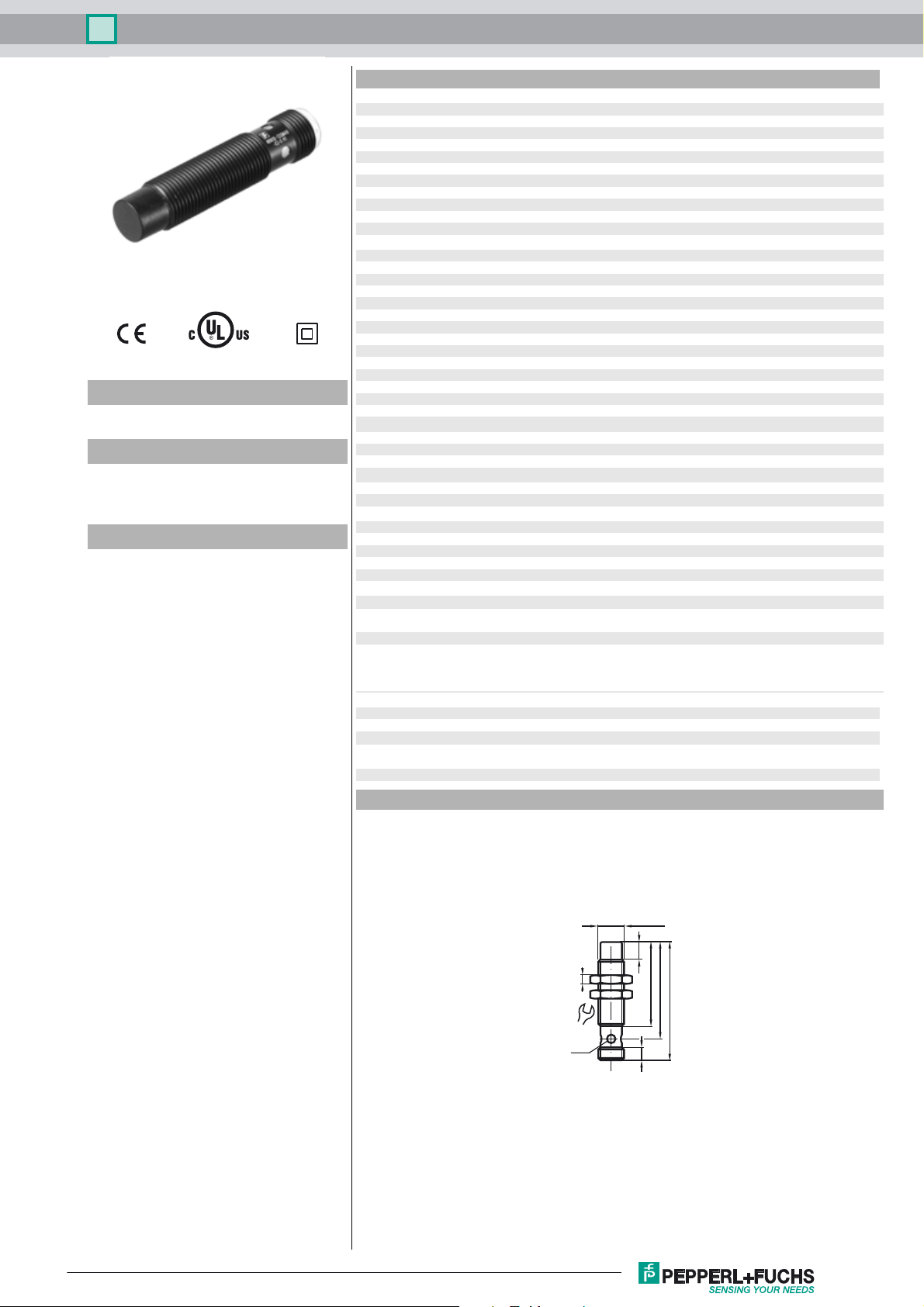
Dimensions
0 ... 8.1 mm
a
≤ 2 V
d
60 V
BIS
0 ... 200 mA
L
0 ... 0.5 mA typ. 0.1 µA at 25 °C
r
≤ 14 mA
0
≤ 15 ms
v
EN 60947-5-2:2007
EN 60947-5-2/A1:2012
IEC 60947-5-2:2007
IEC 60947-5-2 AMD 1:2012
60 V
i
800 V
imp
Class 2 power source
Release date: 2018-05-28 08:07 Date of issue: 2018-05-28 264603_eng.xml
Refer to “General Notes Relating to Pepperl+Fuchs Product Information”.
17
LED
M12 x 1
4
8
39
45
55
6
1
Inductive sensor NRN10-12GM40-E2-C-V1
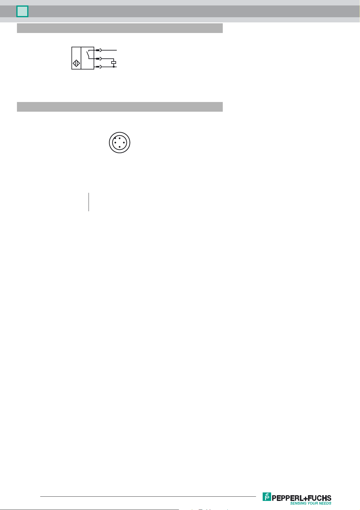
Electrical Connection
Pinout
1
4
3
Wire colors in accordance with EN 60947-5-2
1 BN
2 WH
3 BU
4 BK
2
L+
L-
1
4
3
(brown)
(white)
(blue)
(black)
Release date: 2018-05-28 08:07 Date of issue: 2018-05-28 264603_eng.xml
Refer to “General Notes Relating to Pepperl+Fuchs Product Information”.
2
 Loading...