

Inductive sensor NRB50-FP-E2-C-P3-V1
Technical Data
General specifications
Switching element function PNP NO
Model Number
NRB50-FP-E2-C-P3-V1
Features
• 50 mm flush
• Reduction factor = 1
• Weld Immune
Accessories
V1-G
Female connector, M12, 4-pin, field attachable
V1-W
Female connector, M12, 4-pin, field attachable
V1-G-2M-PUR
Female cordset, M12, 4-pin, PUR cable
V1-W-2M-PUR
Female cordset, M12, 4-pin, PUR cable
Rated operating distance s
Installation flush
Output polarity DC
Assured operating distance sa0 ... 40.5 mm
Reduction factor r
Reduction factor rCu 1
Reduction factor r
Reduction factor r
Nominal ratings
Operating voltage UB10 ... 30 V DC
Switching frequency f 0 ... 1 Hz
Hysteresis H typ. 3 %
Reverse polarity protection reverse polarity protected
Short-circuit protection pulsing
Vol tag e d rop U
Rated insulation voltage U
Operating current I
Off-state current I
No-load supply current I
Time delay before availability t
Operating voltage indicator LED, green
Switching state indicator LED, yellow
Functional safety related parameters
MTTFd 944 a
Mission Time (T
Diagnostic Coverage (DC) 0 %
Ambient conditions
Ambient temperature 0 ... 50 °C (32 ... 122 °F) (± 10 % changing operating distance)
Mechanical specifications
Connection type Connector M12 x 1 , 4-pin
Housing material PBT/metal
Sensing face PBT, PTFE coated
Housing base PBT
Degree of protection IP68
Compliance with standards and directives
Stan dard conf ormit y
Sta ndar ds
Approvals and certificates
UL approval cULus Listed, General Purpose
CSA approval cCSAus Listed, General Purpose
CCC approval CCC approval / marking not required for products rated ≤36 V
1
Al
1
304
1
St37
) 20 a
M
50 mm
n
≤ 3 V
d
50 V
BIS
0 ... 200 mA
L
0 ... 0.5 mA
r
≤ 20 mA
0
≤ 300 ms
v
-25 ... 70 °C (-13 ... 158 °F) (± 20 % changing operating distance)
EN 60947-5-2:2007
IEC 60947-5-2:2007
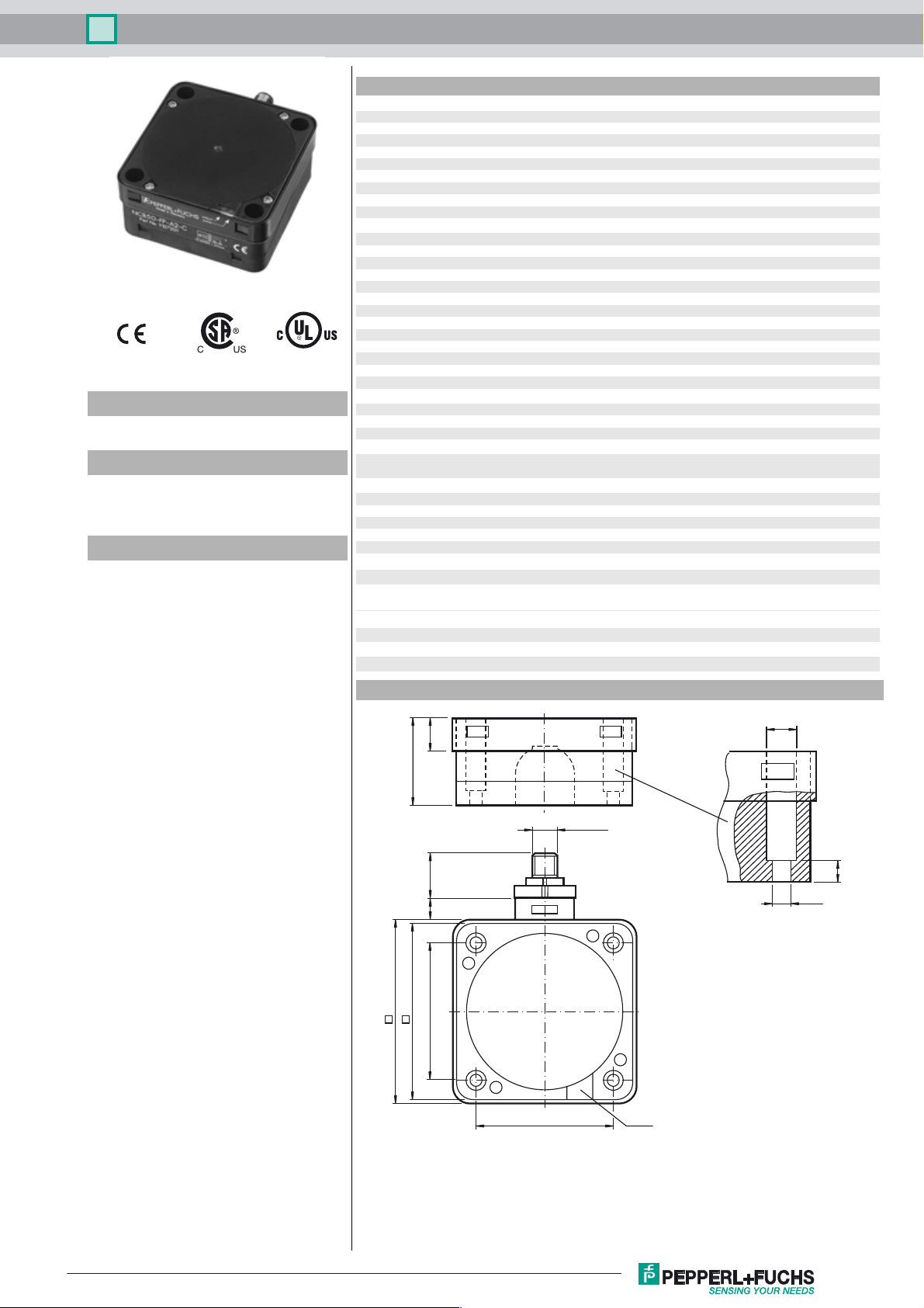
Dimensions
15
40
10 22
84
80
65
ø 9.5
M12 x 1
7
ø 5.3
65
LEDs
Release date: 2015-07-28 09:34 Date of issue: 2015-07-28 187797_eng.xml
Refer to “General Notes Relating to Pepperl+Fuchs Product Information”.
1
Inductive sensor NRB50-FP-E2-C-P3-V1
Electrical Connection
Pinout
1
4
3
Wire colors in accordance with EN 60947-5-2
1 BN
2 WH
3 BU
4 BK
2
L+
L-
1
4
3
(brown)
(white)
(blue)
(black)
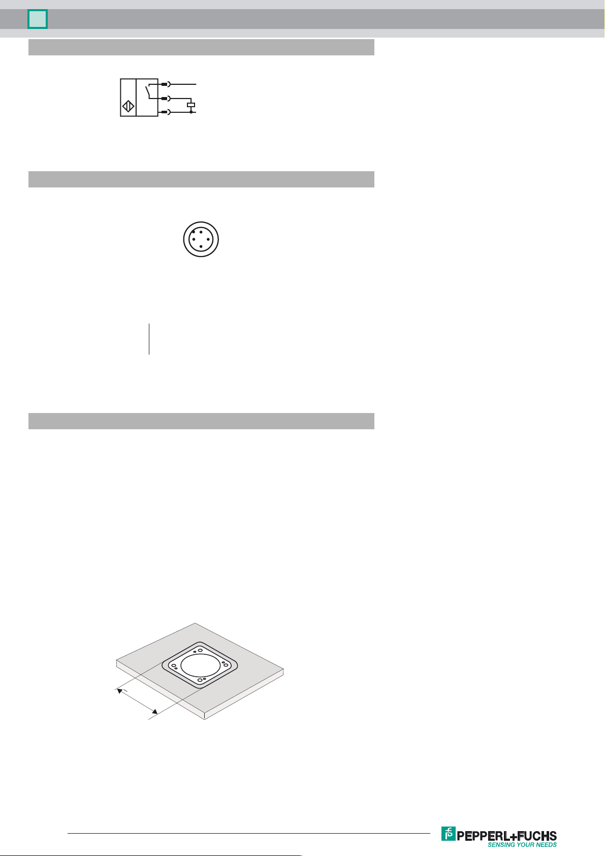
Installation Hint
These sensors are particularly suitable for
embedded installation in floor conveyor
systems. The installation of the switch in
a metal base plate provides it with
considerable protection against
mechanical damage.
Care should be taken to ensure that the
cut out in the base plate is at least
104 mm x 104 mm and that the sensor is
positioned centrally within this cut out.
The active surface of the sensor must not
be recessed with respect to the front face
of the base plate.
The high switching distance guarantees
safe detection and thus control of the floor
conveyor system.
> 104 mm
Caution!
After removal of the metal screen the
proximity switch can no longer be
mounted as an embedded installation.
Release date: 2015-07-28 09:34 Date of issue: 2015-07-28 187797_eng.xml
Refer to “General Notes Relating to Pepperl+Fuchs Product Information”.
2
 Loading...