

Inductive sensor NMN20-18GH50-E2-V1
Technical Data
General specifications
Switching function Normally open (NO)
Output type PNP
Rated operating distance sn20 mm
Installation non-flush
Output polarity DC
Model Number
NMN20-18GH50-E2-V1
Features
• 20 mm non-flush
•Active surface metal
• One-piece housing with stainless steel
(V4A; 1.4435)
Accessories
BF 18
Mounting flange, 18 mm
V1-G
Female connector, M12, 4-pin, field attachable
V1-W
Female connector, M12, 4-pin, field attachable
V1-G-2M-PUR
Female cordset, M12, 4-pin, PUR cable
V1-W-2M-PUR
Female cordset, M12, 4-pin, PUR cable
Assured operating distance s
Reduction factor rAl 1
Reduction factor r
Reduction factor r
Reduction factor r
Output type 3-wire
Nominal ratings
Installation conditions
A
B
C
F
Operating voltage U
Switching frequency f 0 ... 200 Hz
Hysteresis H 3 ... 15 typ. 5 %
Reverse polarity protection yes
Short-circuit protection yes
Voltage drop Ud≤ 2 V
Operating current I
Off-state current I
No-load supply current I
Time delay before availability t
Switching state indicator LED, yellow
Limit data
Operating pressure statically 60 bar (870.2 psi) max.
Functional safety related parameters
MTTFd 655 a
Mission Time (TM) 20 a
Diagnostic Coverage (DC) 0 %
Ambient conditions
Ambient temperature -25 ... 85 °C (-13 ... 185 °F)
Mechanical specifications
Connection type Connector plug M12 x 1 , 4-pin
Housing material Stainless steel 1.4435 / AISI 316L
Sensing face Stainless steel 1.4435 / AISI 316L
Degree of protection IP68 / IP69K
Mass 24 g
Compliance with standards and
directives
Standard conformity
Standards
Approvals and certificates
UL approval cULus Listed, General Purpose
CCC approval CCC approval / marking not required for products rated ≤36 V
0.9
Cu
0.3 (0.6 of material thickness 2 mm)
304
1
St37
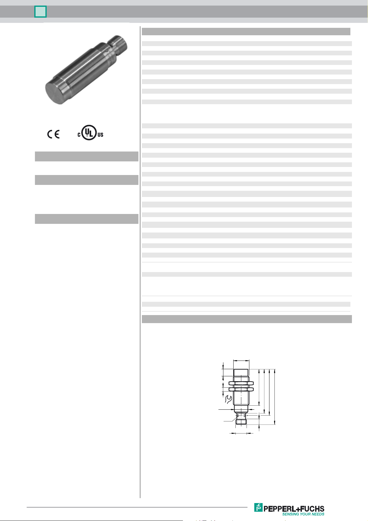
Dimensions
0 ... 16.2 mm
a
34 mm (mild steel)
36 mm (stainless steel)
20 mm (aluminum)
22 mm (brass)
41 mm
60 mm
200 mm
10 ... 30 V
B
0 ... 200 mA
L
≤ 0.1 mA
r
≤ 10 mA
0
≤ 40 ms
v
EN 60947-5-2:2007
EN 60947-5-2/A1:2012
IEC 60947-5-2:2007
IEC 60947-5-2 AMD 1:2012
Release date: 2017-12-20 14:02 Date of issue: 2017-12-20 288266_eng.xml
Refer to “General Notes Relating to Pepperl+Fuchs Product Information”.
7
4
24
ø 16.4
LED
(4x)
M18 x 1
M12 x 1
42
50
52.5
63.5
8
1
Inductive sensor NMN20-18GH50-E2-V1
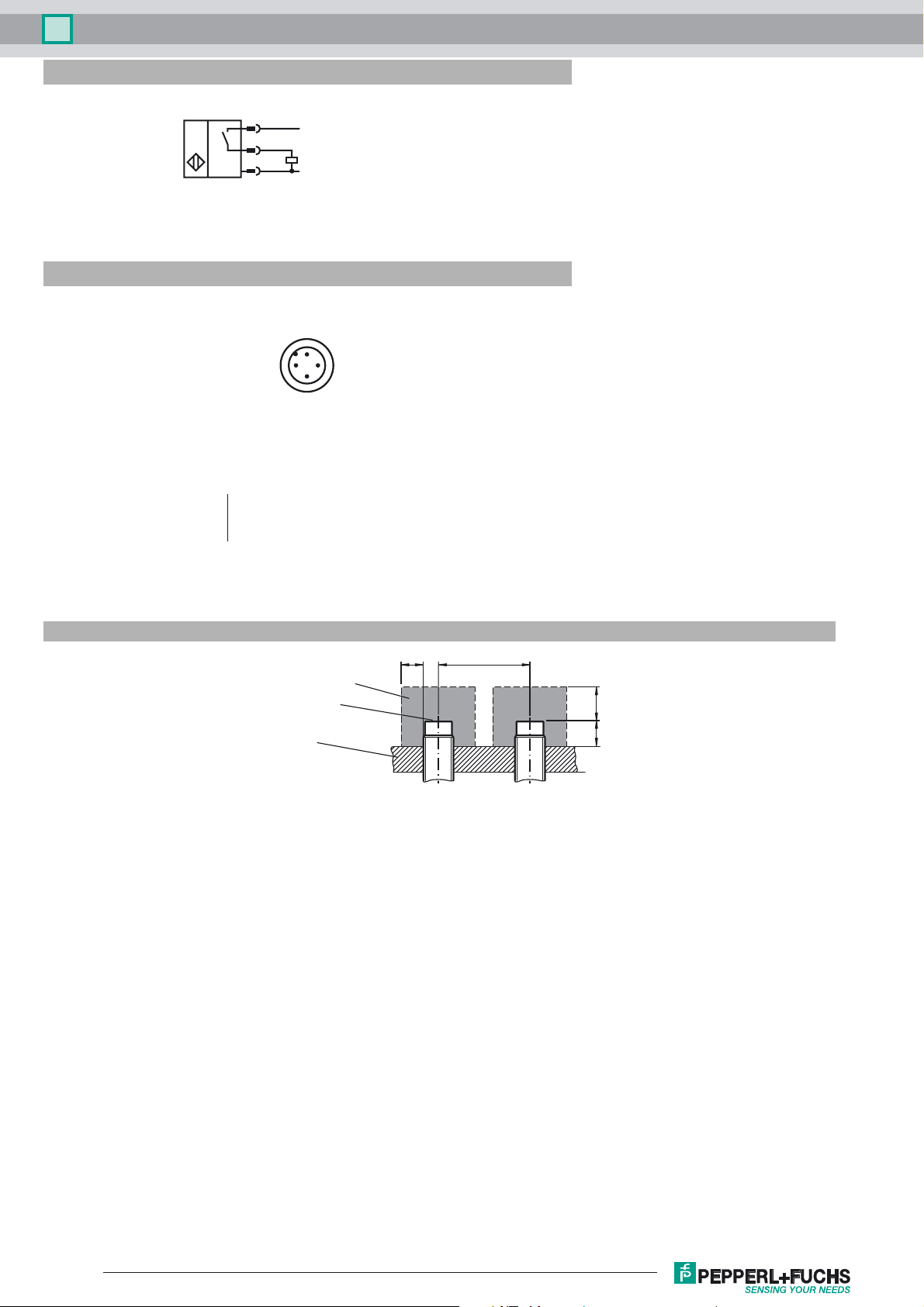
Electrical Connection
Pinout
1
4
3
Wire colors in accordance with EN 60947-5-2
1 BN
2 WH
3 BU
4 BK
2
L+
L-
1
4
3
(brown)
(white)
(blue)
(black)
Installation Conditions
metal-free zone
sensing face
support
B F
CA
Release date: 2017-12-20 14:02 Date of issue: 2017-12-20 288266_eng.xml
Refer to “General Notes Relating to Pepperl+Fuchs Product Information”.
2
 Loading...