

Inductive sensor NMB10-18GM65-E2-C-V1
Technical Data
General specifications
Switching function Normally open (NO)
Output type PNP
Rated operating distance sn10 mm
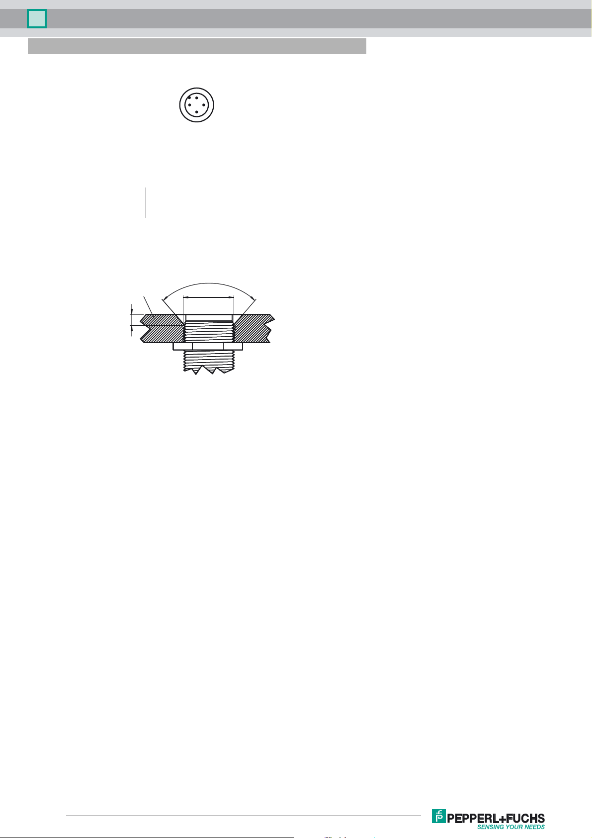
Installation flush (Requirements: see drawing below)
Output polarity DC
Model Number
NMB10-18GM65-E2-C-V1
Features
• 10 mm flush
• Stainless steel sensing face
• Increased operating distance
• Weld Immune
Accessories
AB-18
Mounting aid
V1-G-OR2M-POC
Female cordset, M12, 4-pin, TPE cable, welding-bead resistant
Assured operating distance s
Actuating element Ferrous and nonferrous targets
Reduction factor r
Reduction factor rCu 0.25
Reduction factor r
Reduction factor r
Output type 3-wire
Nominal ratings
Operating voltage UB10 ... 30 V DC
Switching frequency f 0 ... 5 Hz
Hysteresis H 3 ... 15 typ. 5 %
Reverse polarity protection reverse polarity protected
Short-circuit protection pulsing
Vol tag e d rop Ud≤ 2 V
Operating current I
Current consumption ≤ 10 mA
Off-state current I
No-load supply current I
Operating voltage indicator LED, green
Switching state indicator Multihole-LED, yellow
Mag. Field strength, AC fields 250 mT
Mag. Field strength, DC fields 250 mT
Functional safety related parameters
MTTFd 906 a
Mission Time (T
Diagnostic Coverage (DC) 0 %
Ambient conditions
Ambient temperature -25 ... 70 °C (-13 ... 158 °F)
Mechanical specifications
Connection type Connector M12 x 1 , 4-pin
Housing material Xylan coated - Stainless steel 1.4305 / AISI 303
Sensing face Xylan coated - Stainless steel 1.4305 / AISI 303
Degree of protection IP67
Compliance with standards and directives
Stan dard conf ormit y
Sta ndar ds
Approvals and certificates
UL approval cULus Listed, General Purpose
CSA approval cCSAus Listed, General Purpose
CCC approval CCC approval / marking not required for products rated ≤36 V
0.4
Al
0.85
304
1
St37
) 20 a
M
0 ... 8.1 mm
a
0 ... 200 mA
L
≤ 10 µA
r
≤ 15 mA
0
EN 60947-5-2:2007
IEC 60947-5-2:2007
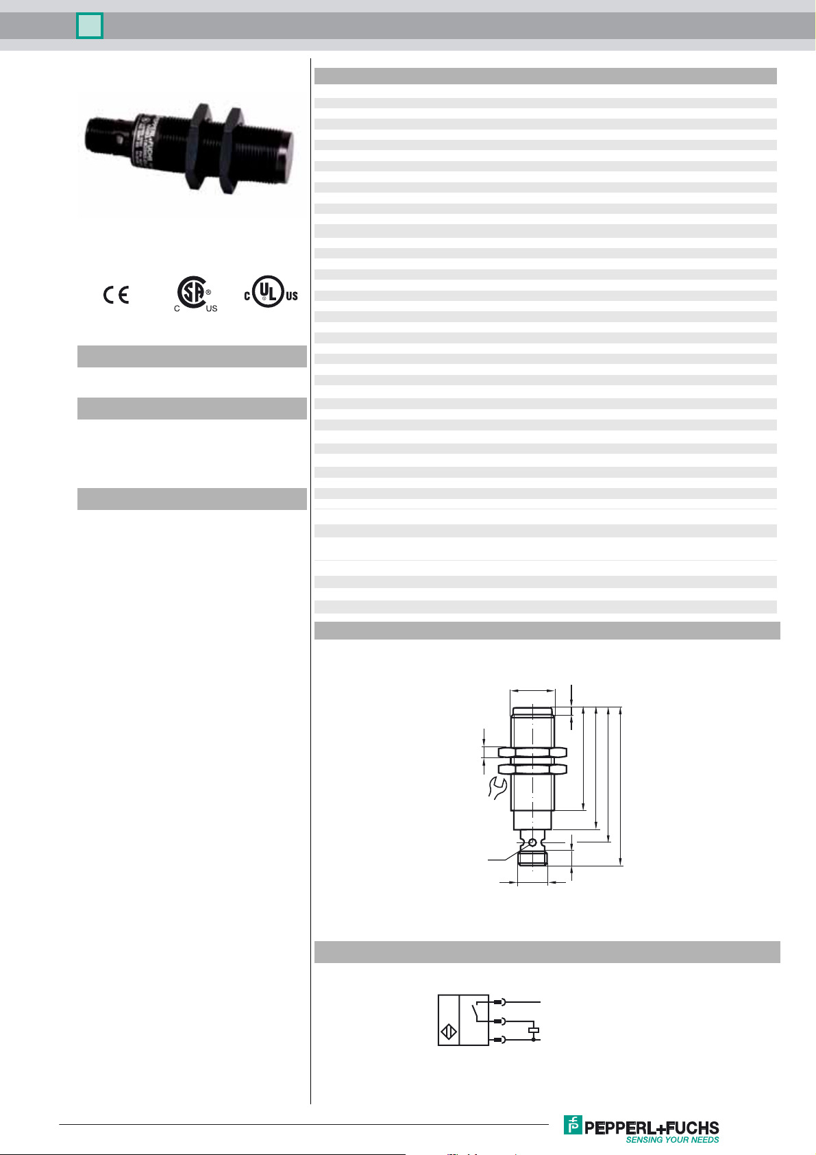
Dimensions
Electrical Connection
M18x1
2.5
4
24
LED
42
50
55
65
6
M12x1
1
L+
4
3
L-
Release date: 2017-03-15 08:30 Date of issue: 2017-03-15 911270_eng.xml
Refer to “General Notes Relating to Pepperl+Fuchs Product Information”.
1
Inductive sensor NMB10-18GM65-E2-C-V1
Pinout
1
2
Wire colors in accordance with EN 60947-5-2
1 BN
2 WH
3 BU
4 BK
(brown)
(white)
(blue)
(black)
Mild Steel
≥ 4
4
3
≥ 82°
18
Sensor face is flush with mounting surface.
Release date: 2017-03-15 08:30 Date of issue: 2017-03-15 911270_eng.xml
Refer to “General Notes Relating to Pepperl+Fuchs Product Information”.
2
 Loading...