

Inductive sensor NMB10-18GM65-E0-V1
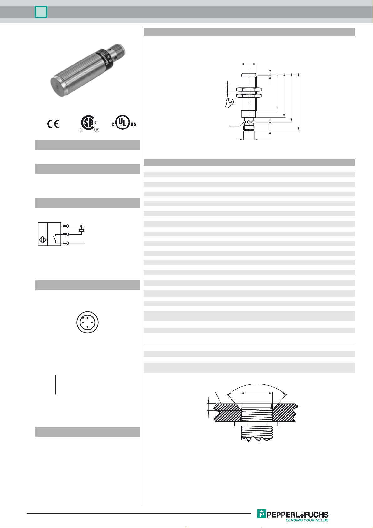
Dimensions
M18 x 1
Model Number
NMB10-18GM65-E0-V1
Features
•10 mm flush
• Stainless steel sensing face
• Increased operating distance
Connection
1
4
3
L+
L-
Pinout
1
2
Wire colors in accordance with EN 60947-5-2
1 BN
2 WH
3 BU
4 BK
(brown)
(white)
(blue)
(black)
4
3
4
24
LED
M12 x 1
2.5
6
42
50
55
65
Technical Data
General specifications
Switching element function NPN NO
Rated operating distance s
Installation flush (Requirements: see drawing below)
Output polarity DC
Assured operating distance sa0 ... 8.1 mm
Actuating element Ferrous and nonferrous targets
Reduction factor rAl 0.4
Reduction factor r
Reduction factor r
Reduction factor r
Nominal ratings
Operating voltage UB10 ... 30 V DC
Switching frequency f 0 ... 240 Hz
Hysteresis H 3 ... 15 typ. 10 %
Reverse polarity protection reverse polarity protected
Short-circuit protection pulsing
Voltage drop Ud≤ 2 V
Operating current I
Off-state current I
No-load supply current I
Operating voltage display LED, green
Indication of the switching state LED, yellow
Ambient conditions
Ambient temperature -25 ... 70 °C (-13 ... 158 °F)
Mechanical specifications
Connection type Device connector M12 x 1 , 4-pin
Housing material Stainless steel 1.4305 / AISI 303
Sensing face Stainless steel 1.4305 / AISI 303
Protection degree IP67 / IP68 / IP69K - cordset dependent according to cable speci-
Compliance with standards and directives
Standard conformity
Standards
Approvals and certificates
UL approval cULus Listed, General Purpose
CSA approval cCSAus Listed, General Purpose
CCC approval Products with a maximum operating voltage of ≤36 V do not bear a
0.25
Cu
0.85
304
1
St37
Mild Steel
10 mm
n
≤ 200 mA
L
10 µA
r
≤ 10 mA
0
fication
EN 60947-5-2:2007
IEC 60947-5-2:2007
CCC marking because they do not require approval.
≥ 82°
18
Accessories
V1-G-2M-PUR
Cable socket, M12, 4-pin, PUR cable
V1-W-2M-PUR
Cable socket, M12, 4-pin, PUR cable
Release date: 2012-12-13 14:33 Date of issue: 2012-12-13 911276_eng.xml
Subject to modifications without notice
≥ 4
Sensor face is flush with mounting surface.
Copyright Pepperl+Fuchs
1
 Loading...