

Pepperl Fuchs NJ8-18GM50-E-V1 Data Sheet
Inductive sensor NJ8-18GM50-E-V1
Technical Data
General specifications
Switching function Normally open (NO)
Output type NPN
Rated operating distance sn8 mm
Installation non-flush
Output polarity DC
Model Number
NJ8-18GM50-E-V1
Features
•Comfort series
• 8 mm non-flush
Accessories
BF 18
Mounting flange, 18 mm
V1-G
Female connector, M12, 4-pin, field attachable
V1-W
Female connector, M12, 4-pin, field attachable
V1-G-2M-PUR
Female cordset, M12, 4-pin, PUR cable
V1-W-2M-PUR
Female cordset, M12, 4-pin, PUR cable
Assured operating distance s
Actual operating distance sr7.2 ... 8.8 mm typ. 8 mm
Reduction factor r
Reduction factor rCu 0.4
Reduction factor r
Reduction factor r
Nominal ratings
Installation conditions
A
B
C
Operating voltage UB10 ... 60 V
S
Switching frequency f 0 ... 1000 Hz
Hysteresis H 1 ... 10 typ. 6 %
Reverse polarity protection reverse polarity protected
Short-circuit protection pulsing
Vol tag e d rop U
Vol tag e d rop at IL
Vol tage dro p I
ment on U
Design data
Operating current I
Lowest operating current I
Off-state current I
Off-state current TU =40 °C, switching ele-
ment off
No-load supply current I
Time delay before availability t
Switching state indicator LED, yellow
Functional safety related parameters
MTTFd 1410 a
Mission Time (TM) 20 a
Diagnostic Coverage (DC) 0 %
Ambient conditions
Ambient temperature -25 ... 70 °C (-13 ... 158 °F)
Storage temperature -40 ... 85 °C (-40 ... 185 °F)
Mechanical specifications
Connection type Connector M12 x 1 , 3-pin
Housing material Stainless steel 1.4305 / AISI 303
Sensing face PBT
Degree of protection IP67
Compliance with standards and directives
Stan dard conf ormit y
Sta ndar ds
Approvals and certificates
UL approval cULus Listed, General Purpose
CSA approval cCSAus Listed, General Purpose
CCC approval Certified by China Compulsory Certification (CCC)
0.42
Al
0.72
304
0.5
Brass
= 100 mA, switching ele-
L
d
0 ... 6.48 mm
a
10 mm
54 mm
24 mm
≤ 3 V
d
1.5 ... 2.5 V typ. 1.9 V
0 ... 200 mA
L
0 mA
m
0 ... 0.5 mA typ. 0.01 mA
r
≤ 100 µA
≤ 9 mA
0
≤ 30 ms
v
EN 60947-5-2:2007
IEC 60947-5-2:2007
Release date: 2016-11-10 09:32 Date of issue: 2016-11-10 282974_eng.xml
Refer to “General Notes Relating to Pepperl+Fuchs Product Information”.
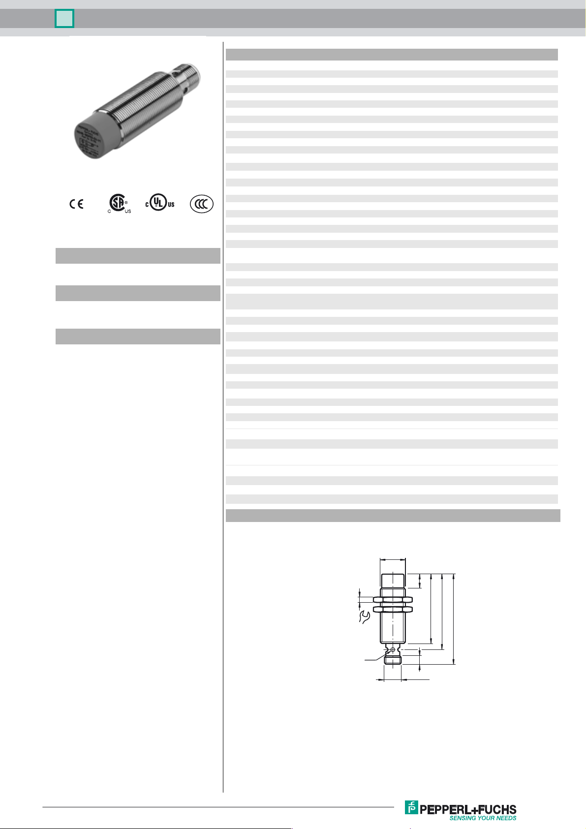
Dimensions
M18 x 1
10
4
50
55
24
LED
6
65
M12 x 1
1
Inductive sensor NJ8-18GM50-E-V1
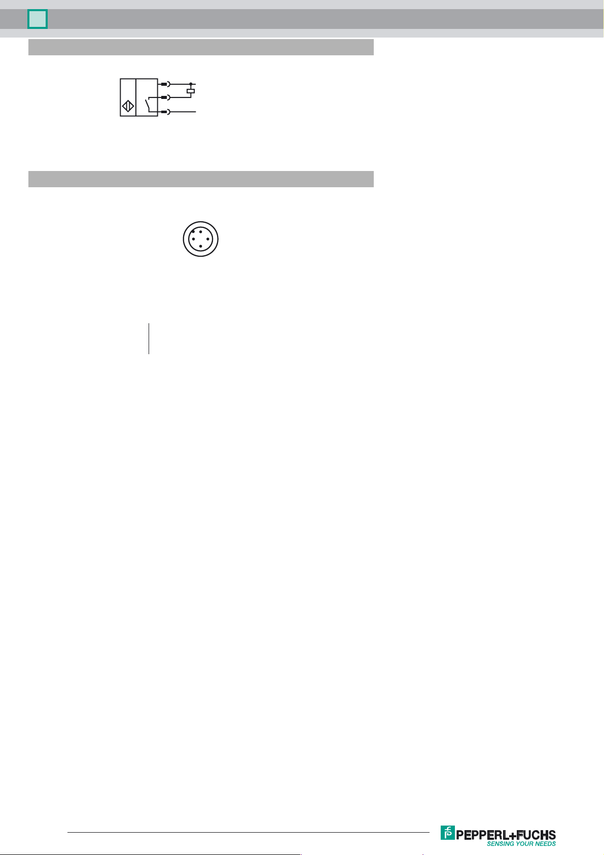
Electrical Connection
Pinout
1
4
3
Wire colors in accordance with EN 60947-5-2
1 BN
2 WH
3 BU
4 BK
2
L+
L-
1
4
3
(brown)
(white)
(blue)
(black)
Release date: 2016-11-10 09:32 Date of issue: 2016-11-10 282974_eng.xml
Refer to “General Notes Relating to Pepperl+Fuchs Product Information”.
2
 Loading...