

Inductive sensor NJ60-FP-E2-P2
Technical Data
General specifications
Switching element function PNP NO
Model Number
NJ60-FP-E2-P2
Features
•3-wire DC
• Surface mount
• Sensing range 60 mm
• Operating distance adjustable via potentiometer
Rated operating distance s
Installation non-flush
Output polarity switched high
Assured operating distance sa0 ... 48.6 mm
Reduction factor r
Reduction factor rCu 0.3
Reduction factor r
Adjustment aid LED, green/red
Nominal ratings
Operating voltage UB10 ... 30 V
Switching frequency f 0 ... 20 Hz
Hysteresis H 3 ... 15 typ. 5 %
Reverse polarity protection yes
Short-circuit protection pulsing
Vol tag e d rop U
Operating current I
No-load supply current I
Time delay before availability t
Operating voltage indicator LED, green
Switching state indicator LED, red
Ambient conditions
Ambient temperature 0 ... 60 °C (32 ... 140 °F)
Mechanical specifications
Connection type screw terminals
Core cross-section up to 2.5 mm
Housing material POM
Sensing face POM
Degree of protection IP65
Compliance with standards and directives
Stan dard conf ormit y
Sta ndar ds
Approvals and certificates
UL approval cULus Listed, General Purpose
CSA approval cCSAus Listed, General Purpose
0.4
Al
0.85
304
60 mm
n
≤ 3 V
d
0 ... 200 mA
L
≤ 20 mA
0
≤ 20 ms
v
EN 60947-5-2:2007
IEC 60947-5-2:2007
2
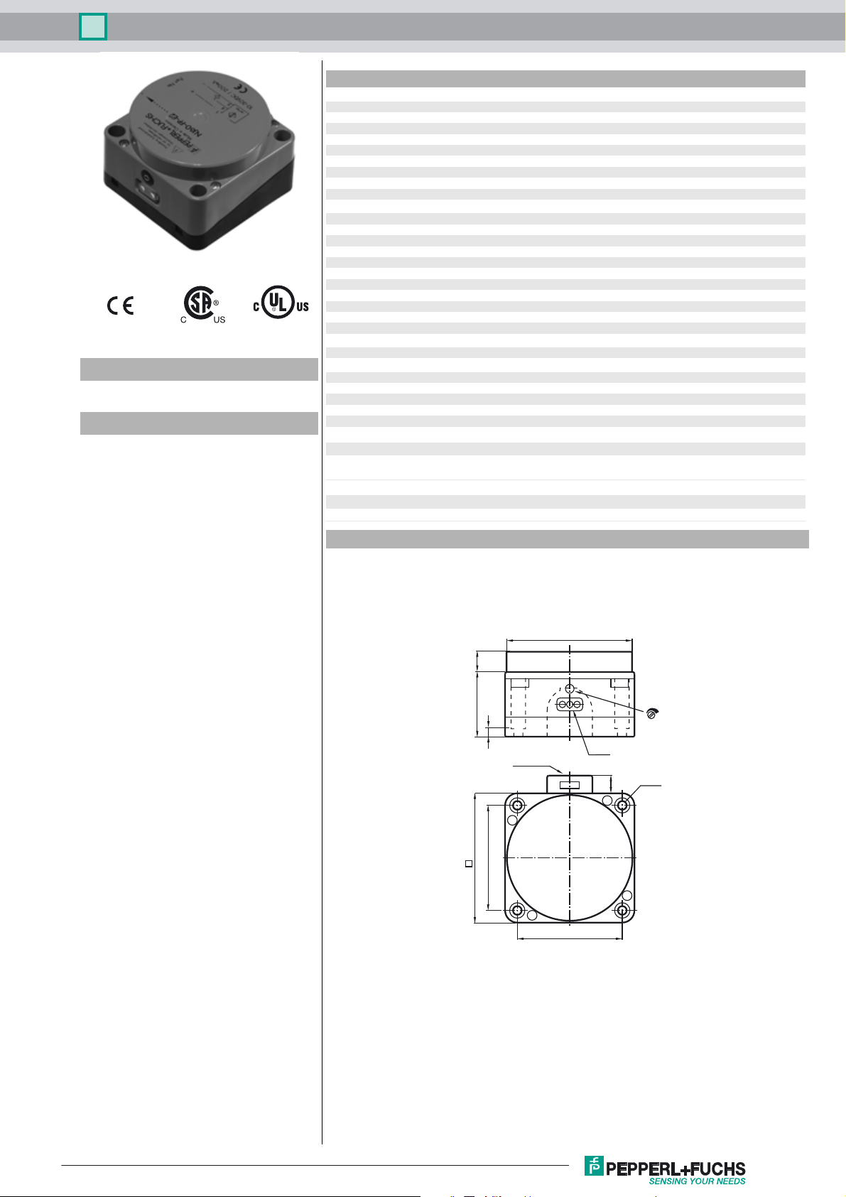
Dimensions
12.4
40
80
65
7
1/2" NPT
ø 80
65
LEDs
Sn
ø 5.3
11
Release date: 2015-02-17 15:14 Date of issue: 2015-02-17 904843_eng.xml
Refer to “General Notes Relating to Pepperl+Fuchs Product Information”.
1
Inductive sensor NJ60-FP-E2-P2
Electrical Connection
Installation Hint
1
4
3
L+
L-
Installation
The sensor should be mounted at least 30 mm
above the conveyor chain. This ensures, that
the sensor will not be influenced by the
conveyor chain.
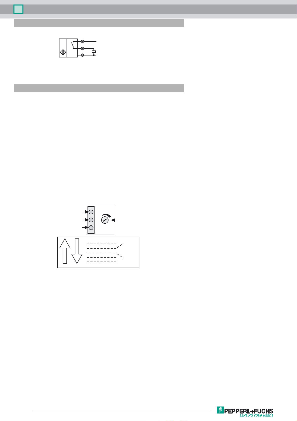
Adjustment:
For correct operation, the sensor has to be
adjusted according to the application.
The adjustment has to be carried out without
the object, which has to be detected.
1) Supply the sensor (10 ... 30 V DC).
leuchtet die grüne LED.
2) If the output is activated,
the yellow LED is on
3) The adjustment is made without
measuring body
The double LED in the middle has to light up
green. If it doesn't, turn the sensitivity adjuster
clockwise until the LED lights up yellow. Now
turn the sensitivity adjuster counterclockwise
until the double LED lights up green.
Supply voltage
LED green
Adjustment aid:
double LED
green / red
Output:
LED yellow
counterclockwise
Double LED lights up red
Double LED off
Double LED lights up green
clockwise
Double LED off
Double LED lights up red
yellow LED on
Sensitivity
adjuster
Sn
adjust this
range!
Function check:
To check the correct adjustment, test the
reliable detection of a stainless steel test tube
in the bottle.
Release date: 2015-02-17 15:14 Date of issue: 2015-02-17 904843_eng.xml
Refer to “General Notes Relating to Pepperl+Fuchs Product Information”.
2
 Loading...