

Inductive sensor NJ5-18GM50-E2-3G-3D-5M
Technical Data
General specifications
Switching function Normally open (NO)
Output type PNP
Rated operating distance sn5 mm
Installation flush
Output polarity DC
Model Number
NJ5-18GM50-E2-3G-3D-5M
Features
•Comfort series
•5 mm flush
Accessories
BF 18
Mounting flange, 18 mm
EXG-18
Quick mounting bracket with dead stop
Assured operating distance s
Actual operating distance sr4.5 ... 5.5 mm typ. 5 mm
Reduction factor r
Reduction factor rCu 0.15
Reduction factor r
Nominal ratings
Installation conditions
A
B
C
Operating voltage U
Switching frequency f 0 ... 1500 Hz
S
Hysteresis H 1 ... 15 typ. 6 %
Reverse polarity protection reverse polarity protected
Short-circuit protection pulsing
Vol tag e d rop Ud≤ 3 V
Vol tag e d rop at I
Vol tage dro p IL = 100 mA, switching ele-
ment on U
Operating current I
Lowest operating current I
Off-state current I
Off-state current TU =40 °C, switching ele-
ment off
No-load supply current I
Time delay before availability t
Switching state indicator LED, yellow
Functional safety related parameters
MTTFd 1100 a
Mission Time (TM) 20 a
Diagnostic Coverage (DC) 0 %
Ambient conditions
Ambient temperature -25 ... 70 °C (-13 ... 158 °F)
Storage temperature -40 ... 85 °C (-40 ... 185 °F)
Mechanical specifications
Connection type cable PVC , 5 m
Core cross-section 0.5 mm
Housing material Stainless steel 1.4305 / AISI 303
Sensing face PBT
Degree of protection IP67
Cable
Bending radius
General information
Use in the hazardous area see instruction manuals
Category
Compliance with standards and directives
Stan dard conf ormit y
Sta ndar ds
Approvals and certificates
UL approval cULus Listed, General Purpose
CSA approval cCSAus Listed, General Purpose
CCC approval Certified by China Compulsory Certification (CCC)
0.2
Al
0.62
304
L
d
0 ... 4.05 mm
a
0 mm
0 mm
15 mm
10 ... 60 V
B
1.5 ... 2.5 V typ. 1.9 V
0 ... 200 mA
L
0 mA
m
0 ... 0.5 mA typ. 0.01 mA
r
≤ 100 µA
≤ 9 mA
0
≤ 30 ms
v
2
> 10 x cable diameter
3G; 3D
EN 60947-5-2:2007
IEC 60947-5-2:2007
Release date: 2016-11-07 10:09 Date of issue: 2016-11-07 202692_eng.xml
Refer to “General Notes Relating to Pepperl+Fuchs Product Information”.
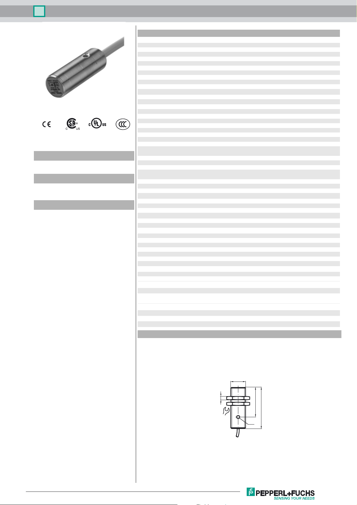
Dimensions
M18x1
4
24
36
50
LED
1
Inductive sensor NJ5-18GM50-E2-3G-3D-5M
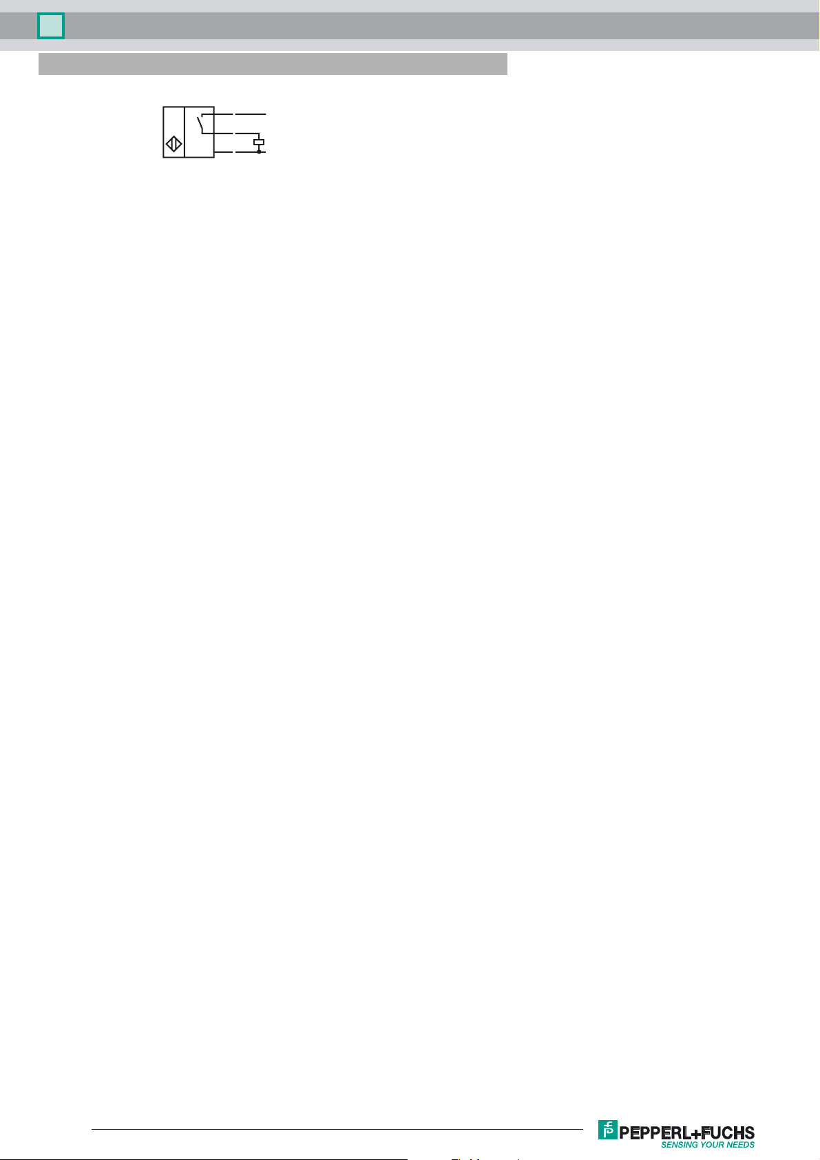
Electrical Connection
BN
BK
BU
L+
L-
Release date: 2016-11-07 10:09 Date of issue: 2016-11-07 202692_eng.xml
Refer to “General Notes Relating to Pepperl+Fuchs Product Information”.
2

Inductive sensor NJ5-18GM50-E2-3G-3D-5M
Equipment protection level Gc (nA)
Instruction Manual electrical apparatus for hazardous areas
Device category 3G (nA) for use in hazardous areas with gas, vapour and mist
Certificate of Compliance PF 15CERT3754 X
CE marking
ATEX ma rk in g ¬ II 3G Ex nA IIC T6 Gc
Standards EN 60079-0:2012+A11:2013, EN 60079-15:2010
Ge n e r a l The apparatus has to be operated according to the appropriate data in the data sheet
Installation, commissioning Laws and/or regulations and standards governing the use or intended usage goal must
Maintenance No changes can be made to apparatus, which are operated in hazardous areas.
Special conditions
Maximum operating current I
Maximum operating voltage U
Maximum permissible ambient temperature T
at U
at U
at U
=60 V, IL=200 mA
Bmax
=60 V, IL=100 mA
Bmax
=30 V, IL=200 mA
Bmax
L
Bmax
Umax
Protection from mechanical danger
Protection from UV light
Protection of the connection cable
Protection against transients
Electrostatic charge
Material selection accessories
The Ex-related marking can also be printed on the enclosed label.
Ignition protection category "n"
Use is restricted to the following stated conditions
and in this instruction manual. The data stated in the data sheet are restricted by this
operating instruction! The special conditions must be observed!
be observed. If the Ex-related marking is printed only on the supplied label, then this
must be attached in the immediate vicinity of the sensor. The sticking surface for the
label must be clean and free from grease. The attached label must be legible and indelible, including in the event of possible chemical corrosion.
Repairs to these apparatus are not possible.
The maximum permissible load current must be restricted to the values given in the following list. High load currents and load short-circuits are not permitted.
The maximum permissible operating voltage UB max is restricted to the values in the
following list. Tolerances are not permissible.
dependant of the load current I
Information can be taken from the following list.
and the max. operating voltage U
L
Bmax
48 °C (118.4 °F)
52 °C (125.6 °F)
52 °C (125.6 °F)
The sensor must not be exposed to ANY FORM of mechanical danger.
The sensor and the connection cable must be protected from damaging UV-radiation.
This can be achieved when the sensor is used in internal areas.
The connection cable must be prevented from being subjected to tension and torsional
loading.
Ensure transient protection is provided and that the maximum value of the transient pro-
tection (140% of 85 V) is not exceeded.
Electrostatic charges must be avoided on the mechanical housing components. Dan-
gerous electrostatic charges on the mechanical housing components can be avoided by
incorporating these in the equipotential bonding.
When selecting accessories, ensure that the material allows the temperature of the
enclosure to rise to up to 70 °C.
Release date: 2016-11-07 10:09 Date of issue: 2016-11-07 202692_eng.xml
Refer to “General Notes Relating to Pepperl+Fuchs Product Information”.
3

Inductive sensor NJ5-18GM50-E2-3G-3D-5M
Equipment protection level Dc
Note This instruction is only valid for products according to EN 50281-1-1, valid until 30-September-2008
Instruction Manual electrical apparatus for hazardous areas
Device category 3D for use in hazardous areas with non-conducting combustible dust
CE marking
ATEX marking ¬ II 3D IP67 T 94 °C (201.2 °F) X
Standards EN 50281-1-1
General The apparatus has to be operated according to the appropriate data in the data sheet and in this instruction manual.
Installation, commissioning Laws and/or regulations and standards governing the use or intended usage goal must be observed.
Maintenance No changes can be made to apparatus, which are operated in hazardous areas.
Special conditions
Maximum operating voltage U
Maximum operating current I
Maximum heating (Temperature rise)
at U
at U
at U
Protection from mechanical danger
Protection of the connection cable
Electrostatic charge
=60 V, IL=200 mA
Bmax
=60 V, IL=100 mA
Bmax
=30 V, IL=200 mA
Bmax
Note the ex-marking on the sensor or on the enclosed adhesive label
Protection via housing
Use is restricted to the following stated conditions
The data stated in the data sheet are restricted by this operating instruction! The special conditions must be adhered to!
Repairs to these apparatus are not possible.
The maximum permissible operating voltage UBmax must be restricted to the values given in the following list. Tolerances are
Bmax
not permitted.
The maximum permissible load current must be restricted to the values given in the following list.
L
High load currents and load short-circuits are not permitted.
dependant of the load current I
Information can be taken from the following list. The maximum surface temperature at maximum ambient temperature is given
in the Ex identification of the apparatus.
24 K
19 K
19 K
The sensor must not be mechanically damaged.
The connection cable must be prevented from being subjected to tension and torsional loading.
Electrostatic charges must be avoided on the mechanical housing components. Dangerous electrostatic charges on the
mechanical housing components can be avoided by incorporating these in the equipotential bonding.
and the max. operating voltage U
L
Bmax
Release date: 2016-11-07 10:09 Date of issue: 2016-11-07 202692_eng.xml
Refer to “General Notes Relating to Pepperl+Fuchs Product Information”.
4

Inductive sensor NJ5-18GM50-E2-3G-3D-5M
Equipment protection level Dc (tD)
Note This instruction is only valid for products according to EN 61241-0:2006 and EN 61241-1:2004
Instruction Manual electrical apparatus for hazardous areas
Device category 3D for use in hazardous areas with combustible dust
CE marking
ATEX ma rk in g ¬ II 3D Ex tD A22 IP67 T80°C X
Standards EN 61241-0:2006, EN 61241-1:2004
General The apparatus has to be operated according to the appropriate data in the data sheet and in this instruction manual.
Installation, commissioning Laws and/or regulations and standards governing the use or intended usage goal must be observed.
Maintenance No changes can be made to apparatus, which are operated in hazardous areas.
Special conditions
Maximum operating current I
Maximum operating voltage U
Maximum permissible ambient temperature T
at U
at U
at U
Umax
=60 V, IL=200 mA
Bmax
=60 V, IL=100 mA
Bmax
=30 V, IL=200 mA
Bmax
L
Bmax
Protection from mechanical danger
Protection from UV light
Protection of the connection cable
Electrostatic charge
Note the ex-marking on the sensor or on the enclosed adhesive label
Protection via housing "tD"
Use is restricted to the following stated conditions
The maximum surface temperature has been determined in accordance with method A without a dust layer on the equipment.
The data stated in the data sheet are restricted by this operating instruction!
The special conditions must be adhered to!
Repairs to these apparatus are not possible.
The maximum permissible load current must be restricted to the values given in the following list.
High load currents and load short-circuits are not permitted.
The maximum permissible operating voltage UBmax must be restricted to the values given in the following list. Tolerances are
not permitted.
dependant of the load current I
Information can be taken from the following list.
and the max. operating voltage U
L
Bmax
45 °C (113 °F)
51 °C (123.8 °F)
51 °C (123.8 °F)
The sensor must not be exposed to ANY FORM of mechanical danger.
The sensor and the connection cable must be protected from damaging UV-radiation. This can be achieved when the sensor is
used in internal areas.
The connection cable must be prevented from being subjected to tension and torsional loading.
Electrostatic charges must be avoided on the mechanical housing components. Dangerous electrostatic charges on the
mechanical housing components can be avoided by incorporating these in the equipotential bonding.
Release date: 2016-11-07 10:09 Date of issue: 2016-11-07 202692_eng.xml
Refer to “General Notes Relating to Pepperl+Fuchs Product Information”.
5
Inductive sensor NJ5-18GM50-E2-3G-3D-5M
Equipment protection level Dc (tc)
Instruction Manual electrical apparatus for hazardous areas
Device category 3D for use in hazardous areas with combustible dust
Certificate of Compliance PF 15CERT3774 X
CE marking
ATEX marking ¬ II 3D Ex tc IIIC T80°C Dc
Standards EN 60079-0:2012+A11:2013, EN 60079-31:2014
Ge n e r a l The corresponding datasheets, declarations of conformity, EC-type examination certifi-
Installation, commissioning Laws and/or regulations and standards governing the use or intended usage goal must
Maintenance No changes can be made to apparatus, which are operated in hazardous areas.
Special conditions
Maximum operating current I
Maximum operating voltage U
Maximum permissible ambient temperature T
at U
at U
at U
Protection from mechanical danger
=60 V, IL=200 mA
Bmax
=60 V, IL=100 mA
Bmax
=30 V, IL=200 mA
Bmax
L
Bmax
Umax
Protection from UV light
Protection of the connection cable
Electrostatic charge
The Ex-related marking can also be printed on the enclosed label.
Protection by enclosure "tc" Some of the information in this instruction manual is more
specific than the information provided in the datasheet.
cates, certifications, and control drawings, where applicable (see datasheets), form an
integral part of this document. These documents can be found at www.pepperlfuchs.com. The maximum surface temperature of the device was determined without a
layer of dust on the apparatus. Some of the information in this instruction manual is more
specific than the information provided in the datasheet.
be observed. If the Ex-relevant identification is printed exclusively on the adhesive label
provided, this label must be affixed in the immediate vicinity of the sensor! The background surface to which the adhesivelabel is to be applied must be clean and free from
grease! The applied label must be durable and remain legible, with due consideration of
the possibility of chemical corrosion!
Repairs to these apparatus are not possible.
The maximum permissible load current must be restricted to the values given in the following list.
High load currents and load short-circuits are not permitted.
The maximum permissible operating voltage UBmax must be restricted to the values
given in the following list. Tolerances are not permitted.
dependant of the load current I
Information can be taken from the following list.
and the max. operating voltage U
L
Bmax
45 °C (113 °F)
51 °C (123.8 °F)
51 °C (123.8 °F)
The sensor must not be exposed to ANY FORM of mechanical danger.
The sensor and the connection cable must be protected from damaging UV-radiation.
This can be achieved when the sensor is used in internal areas.
The connection cable must be prevented from being subjected to tension and torsional
loading.
Electrostatic charges must be avoided on the mechanical housing components. Dan-
gerous electrostatic charges on the mechanical housing components can be avoided by
incorporating these in the equipotential bonding. Do not attach the nameplate provided
in areas where electrostatic charge can build up.
Release date: 2016-11-07 10:09 Date of issue: 2016-11-07 202692_eng.xml
Refer to “General Notes Relating to Pepperl+Fuchs Product Information”.
6
 Loading...